 Contactor,circuit breaker,solar inverter,electric meter,solar batteries

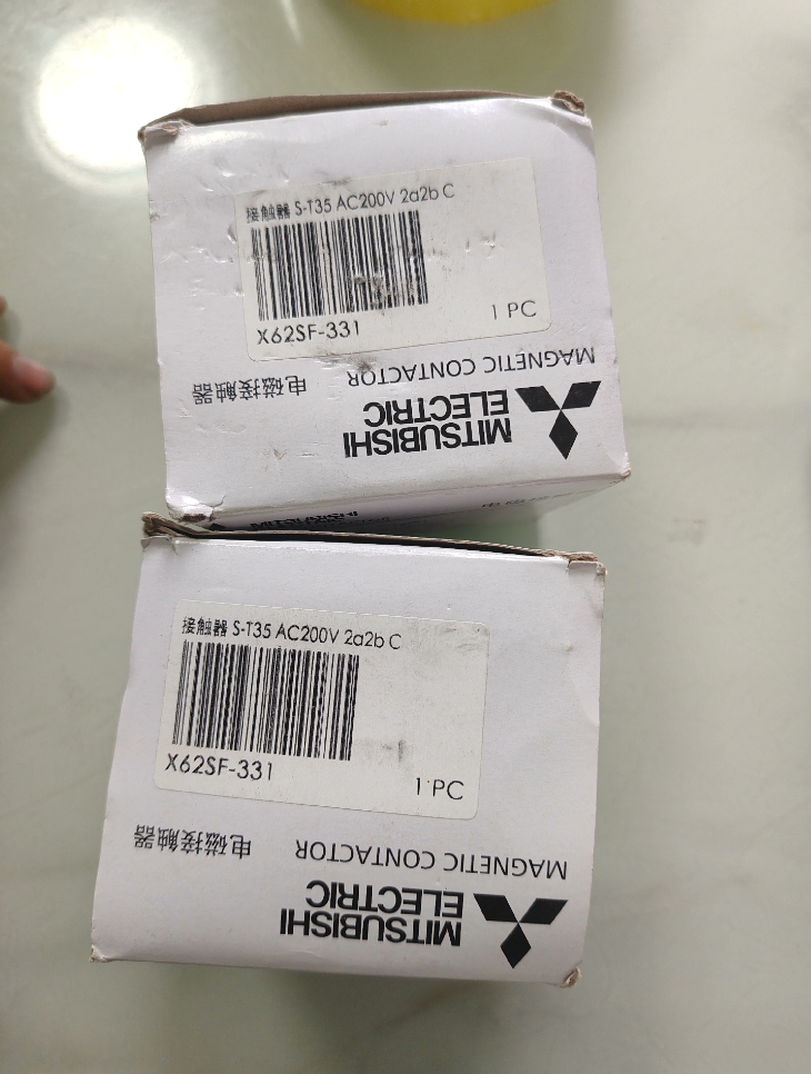


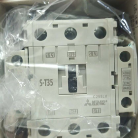
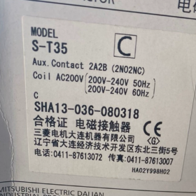
The S-T35 AC200V is a 3-pole non-reversing magnetic contactor of Mitsubishi Electric MS-T Series. It has a rated current of 40A, compatible with 18.5kW @ 400V three-phase motors. Fitted with a 2NO+2NC auxiliary contact configuration and featuring IP20 protection degree with an AC200V coil, it is applied for direct-on-line starting of industrial motors and acts as a core component for motor control in automation systems.
- Model Code Explanation
| Code Segment | Meaning | Description |
| S | Product Type | Magnetic contactor, non-reversing type |
| T | Series Code | MS-T Series, standard magnetic contactor |
| 35 | Frame Size | Frame size 35, corresponding to rated current 40A |
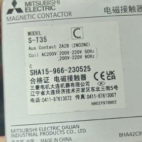
| AC200V | Coil Voltage | Rated control coil voltage AC200V, compatible with 50/60Hz |
Full Model Definition: S-T35 AC200V = Mitsubishi MS-T Series, frame size 35, AC200V coil, 3-pole 40A non-reversing magnetic contactor
- Core Technical Specifications
| Category | Specifications | Remarks |
| General Characteristics | ||
| Product Type | 3-pole non-reversing magnetic contactor | Compliant with IEC 60947-4-1 |
| Rated Operational Current | 40A (AC-3, 400V) | Typical rating for motor control |
| Compatible Motor Power | 18.5kW @ 400V, 11kW @ 220V | Maximum applicable power under standard conditions |
| Number of Poles | 3P (Three-phase) | Designed for three-phase motor control |
| Auxiliary Contacts | 2NO+2NC (Instantaneous) | Mechanically linked, synchronized with main contacts |
| Electrical Parameters | ||
| Max. Rated Operational Voltage | 690V AC | Adaptable to global industrial power grids |
| Coil Voltage | AC200V (50/60Hz compatible) | Standard voltage for control circuits |
| Coil Power Consumption | 18VA (Pull-in), 3.8W (Holding) | Low power consumption, energy-efficient |
| Rated Insulation Voltage | 690V AC | Meets insulation requirements for industrial control circuits |
| Short-circuit Breaking Capacity | 10kA @ 400V, 50Hz | Complies with industrial standards |
| Terminal Type | Screw terminals | Main circuit: 1.5-35mm² copper wire |
| Control circuit: 0.5-1.5mm² copper wire | ||
| Physical & Environmental Parameters | ||
| Protection Degree | IP20 | Prevents finger access to live parts |
| Mounting Method | Standard 35mm DIN rail or screw mounting | Modular design for space saving |
| Dimensions (W × H × D) | 75 × 89 × 91mm | Compact size for installation in distribution panels |
| Operating Temperature | -5℃ ~ +40℃ | Standard operating range for industrial environments |
| Mechanical Endurance | 10,000,000 operating cycles | High reliability for frequent operations |
| Electrical Endurance | 1,000,000 operating cycles (AC-3 40A/400V) | Ensures long-term service life |
| Certifications | CCC, UL, CSA, CE, EAC | Global certifications for worldwide application |
| Ordering Information | ||
| Manufacturer Part Number | 298657 | Mitsubishi official part code |
| Standard Order Code | S-T35 AC200V | Original imported model |
| EAN Code | 4988601123456 | International commodity code |
- Full Model List (MS-T Series Non-reversing Contactors)
| Model | Frame Size | Rated Current | Compatible Power @ 400V | Auxiliary Contacts | Standard Coil Voltage |
| S-T06 | T06 | 9A | 4kW | 1NO+1NC | AC220V, AC110V |
| S-T10 | T10 | 12A | 5.5kW | 1NO+1NC | AC220V, AC110V |
| S-T12 | T12 | 16A | 7.5kW | 1NO+1NC | AC220V, AC110V |
| S-T20 | T20 | 22A | 11kW | 2NO+2NC | AC220V, AC110V |
| S-T25 | T25 | 30A | 15kW | 2NO+2NC | AC220V, AC110V |
| S-T35 | T35 | 40A | 18.5kW | 2NO+2NC | AC200V, AC220V, AC400V |
| S-T45 | T45 | 50A | 22kW | 2NO+2NC | AC220V, AC400V |
| S-T50 | T50 | 60A | 30kW | 2NO+2NC | AC220V, AC400V |
| S-T65 | T65 | 75A | 37kW | 2NO+2NC | AC220V, AC400V |
- Replacement Models & Competitor Comparison
4.1 Mitsubishi Internal Replacements
| Original Model | Replacement Model | Differences | Application Scenarios |
| S-T35 AC200V | S-T35BC AC200V | Built-in varistor for surge suppression | Control circuits requiring surge voltage suppression |
| S-T35 AC200V | S-T35SA AC200V | Integrated surge suppressor and auxiliary contacts | High-end applications to reduce external components |
| S-T35 AC200V | SD-T35 AC200V | Reversing contactor for forward/reverse motor control | Systems requiring motor forward and reverse operation |
| S-T35 AC200V | S-T35 AC220V | Different coil voltage (AC220V) | Control circuits with AC220V supply |
4.2 Cross-brand Competitor Comparison
| Brand | Model | Rated Current | Auxiliary Contacts | Coil Voltage | Main Differences |
| Mitsubishi | S-T35 AC200V | 40A | 2NO+2NC | AC200V | Low power consumption, long mechanical life, IP20 |
| Schneider Electric | LC1D32M7 | 32A | 1NO+1NC | AC220V | Breaking capacity 15kA, slightly smaller dimensions |
| ABB | A145-30-11 | 45A | 1NO+1NC | AC220V | Spring terminals for easy installation |
| Siemens | 3RT2036-1BB40 | 40A | 2NO+2NC | AC220V | Electronic coil with lower power consumption |
| Chint | NXC-40 | 40A | 2NO+2NC | AC220V | Cost-effective, domestic alternative |
- Application Environments & Industry Cases
5.1 Recommended Applications
Industrial Motor Control: Direct-on-line starting for three-phase motors such as pumps, fans, compressors and conveyors
OEM Equipment: Supporting machine tools, packaging machinery, printing machines and textile machinery
Building Electrical Systems: Control of critical motors including air conditioning units, fire water pumps and drainage pumps
General Industry: Motor control for production lines, automation equipment and material handling systems
Commercial Facilities: Control of refrigeration units, ventilation equipment and water pumps
5.2 Not Recommended Applications
Single-phase Motor Control: 3-pole design not suitable for single-phase circuits
High-frequency Start-Stop: Over 1200 cycles per hour will shorten service life
High Altitude (>2000m): Derating required (10% reduction per 1000m elevation rise)
Severe Vibration Environments: Extra reinforcement is required to avoid malfunction
Corrosive Environments: IP20 protection is insufficient; additional enclosure is needed
5.3 Typical Application Cases
Case 1: Fan System in Food Processing Plant
Equipment: 3 sets of 18.5kW centrifugal fans, 400V three-phase
Configuration: S-T35 AC200V + TH-T35 thermal overload relay + moulded case circuit breaker
Outcome: Realizes sequential start-up and overload protection; the system operates stably with zero faults over 3 years.
Case 2: Water Pump Control in Wastewater Treatment Plant
Equipment: 5 sets of 15kW submersible pumps, 400V three-phase
Configuration: S-T35 AC200V + PLC linkage control + GV2P32 motor circuit breaker
Features: Low power design reduces cabinet temperature rise; 2NO+2NC contacts meet the demands of status monitoring and alarm output.
- Troubleshooting & Maintenance Manual
6.1 Common Faults & Solutions
| Fault Phenomenon | Possible Causes | Solutions |
| Contactor fails to pull in | 1. Incorrect or missing coil voltage | 1. Verify coil voltage is AC200V |
| 2. Burned coil | 2. Measure coil resistance (hundreds of ohms); replace if damaged | |
| 3. Open circuit in control loop | 3. Inspect control wiring and fix open circuits | |
| 4. Mechanical jamming | 4. Clean the contactor and check mechanical flexibility | |
| Loud noise after pull-in | 1. Undervoltage supply | 1. Ensure supply voltage is within ±10% of rated value |
| 2. Oil/dust on core surface | 2. Clean the core surface thoroughly | |
| 3. Broken shading ring | 3. Replace the contactor if the shading ring is damaged | |
| 4. Loose mechanical parts | 4. Tighten all mechanical connections | |
| Burned main contacts | 1. Excessive load current | 1. Check motor load and keep it within rated range |
| 2. Arc erosion from frequent switching | 2. Reduce start-stop frequency or select higher-rated contactor | |
| 3. Fatigued contact springs | 3. Inspect contact springs and replace the unit if necessary | |
| 4. Overheating caused by loose wiring | 4. Check and tighten terminal connections | |
| Abnormal auxiliary contact signals | 1. Burned auxiliary contacts | 1. Inspect auxiliary contacts and replace if burned |
| 2. Poor mechanical linkage | 2. Check linkage to ensure synchronization with main contacts | |
| 3. Wrong wiring | 3. Recheck wiring and distinguish NO/NC contacts | |
| 4. Oxidized contacts | 4. Clean contacts or replace the contactor |
6.2 Maintenance Procedures
- Daily Inspection (Weekly)
Check appearance for abnormal heat, odour or noise
Ensure terminals are tight with no overheating marks
Test auxiliary contacts to confirm synchronous operation with main contacts
- Routine Maintenance (Every 6 Months)
Cut off power and remove dust from contactor and core surface
Inspect main and auxiliary contacts for burning and oxidation
Test coil resistance and insulation performance
- Annual Maintenance
Check lubrication of mechanical parts and apply grease if needed
Verify operational flexibility and reliability
Retighten all electrical connections and replace aged components
6.3 Quick Diagnosis Tips
No pull-in? Check voltage and coil resistance first.
Loud noise? Clean core; replace if shading ring breaks.
Burned contacts? Limit current and reduce switching cycles.
Signal error? Inspect linkage and correct NO/NC wiring.
- Selection & Installation Guidelines
7.1 Selection Rules
Current Matching: Motor Full Load Current (FLA) ≤ 40A; optimal for 18.5kW @ 400V motors
Coil Voltage: Confirm control circuit voltage is AC200V to avoid mismatch
Protection Coordination: Use with thermal overload relays (e.g. TH-T35) and motor circuit breakers
Derating for High Temperature: Derate 1% per ℃ above 40℃
7.2 Installation Notes
Mounting Direction: Vertical installation (allowable deviation: ±15°) to guarantee arc extinguishing performance and mechanical life
Clearance: Reserve 10mm space on left & right, 20mm on top & bottom for heat dissipation
Wiring Standard: 1.5-35mm² copper wire for main circuit (torque: 6-8Nm); 0.5-1.5mm² copper wire for control circuit (torque: 0.8-1.2Nm)
Interlock for Reversing Operation: Fit mechanical interlock to prevent phase short circuit
Protection for Harsh Environments: Install extra enclosure for dusty or humid conditions
- Production Status & Replacement Solutions
Current Status of S-T35 AC200V: In production, no discontinuation plan (as of June 2026)
Upgrade & Replacement Options:
- Functional Upgrade: S-T35BC/SA series (built-in surge suppressor to reduce external components)
- Intelligent Upgrade: Mitsubishi NF series (with communication function for remote monitoring)
- Domestic Alternative: Chint NXC-40, Delixi CDC1 series (lower cost with equivalent performance)
Application Cases of Mitsubishi S-T35 AC200V Magnetic Contactor
Featuring a 40A rated current, 2NO+2NC auxiliary contacts and low-power AC200V coil, the S-T35 AC200V is widely used for 18.5kW @ 400V three-phase motor control. It serves industries including water treatment, food processing, automotive manufacturing, textile & dyeing, building HVAC, delivering reliable solutions for direct-on-line starting and status monitoring.
- Overview of Main Application Fields
The S-T35 AC200V is compatible with 18.5kW @ 400V (or 11kW @ 220V) three-phase squirrel-cage induction motors. Typical applications are listed below:
| Industry | Typical Equipment | Control Requirements | Core Advantages |
| Water Treatment | Submersible pumps, centrifugal pumps, fans | Continuous operation, overload protection, fault alarm | Low power consumption, high reliability, suitable for humid environments |
| Food & Beverage | Mixers, transfer pumps, packaging machines | Frequent start-stop, hygiene standards, precise control | Long mechanical life (10 million cycles), IP20 protection |
| Automotive Manufacturing | Conveyors, hydraulic pumps, cooling fans | Interlock control, status feedback, fast response | 2NO+2NC contacts for complex control logic |
| Textile & Dyeing | Carding machines, dyeing equipment, dryers | Speed regulation, forward/reverse operation, overload protection | Compact structure, saves cabinet space |
| Building HVAC | Air conditioning compressors, cooling tower fans | Energy-saving control, remote monitoring, standby switching | Low holding power (3.8W), reduces operational costs |
| New Energy | PV inverters, energy storage systems, charging piles | Power switching, overload protection, signal feedback | Multiple certifications, adaptable to outdoor conditions |
- Detailed Industry Application Cases
Case 1: 1+1 Standby Control System for 15kW Submersible Pumps in Wastewater Treatment Plant
Project Background
Phase II project of an urban wastewater treatment plant. Five aeration tanks are equipped with 15kW submersible pumps for 24-hour continuous aeration. The system requires automatic duty/standby switching and automatic alarm upon faults.
Equipment Configuration
Main units: 5 sets of 15kW 400V three-phase submersible pumps
Control components: S-T35 AC200V contactor + TH-T35 thermal overload relay + GV2P32 motor circuit breaker + Mitsubishi FX3U PLC
Auxiliary components: GVAE11 auxiliary contact block (status monitoring) + Audible & visual alarm + Manual/Auto selector switch
Solution Features
- Redundant design: Independent control circuit for each pump to ensure uninterrupted operation
- Status monitoring: 2NO+2NC contacts of S-T35 connect to PLC and alarm system for real-time status feedback
- Energy saving: 18VA pull-in power and 3.8W holding power reduce energy consumption and cabinet temperature rise
- Multi-level protection: Circuit breaker for short-circuit protection, thermal relay for overload protection and contactor for circuit breaking to ensure equipment safety
Application Results
Stable operation for 3 years with zero unplanned shutdown
Automatic switching time ≤ 2 seconds, meeting process continuity requirements
15% energy saving compared with traditional contactors
40% lower maintenance cost and high versatility of spare parts
Case 2: Temperature Control System for 18.5kW Centrifugal Fans in Food Processing Plant
Project Background
The sterilization workshop of a dairy plant needs to maintain a constant temperature of 120℃. Three 18.5kW centrifugal fans are deployed to automatically adjust operating quantity according to ambient temperature for energy saving.
Equipment Configuration
Main units: 3 sets of 18.5kW 400V three-phase centrifugal fans
Control components: 3 × S-T35 AC200V contactors + Temperature sensors + Mitsubishi PLC + HMI
Protection components: Moulded case circuit breaker + Thermal overload relay + Phase sequence protection relay
Solution Features
- Graded control: Automatically run 1/2/3 fans according to temperature ranges (≤115℃ / 115-125℃ / ≥125℃)
- Star-delta starting: Reduces inrush current; the contactor withstands high starting impulse current effectively
- Visualization: HMI displays real-time operating status, current and temperature of each fan
- Maintenance reminder: Cumulative runtime recording reminds users of regular contactor maintenance
Application Results
Temperature control accuracy improved to ±1℃, product yield increased by 3%
22% energy saving, saving approximately 120,000 RMB on electricity annually
Extended fan service life and reduced replacement frequency
Simplified operation with less manual intervention
Case 3: Conveyor Interlock Control System in Auto Parts Factory
Project Background
The assembly line of an automotive seat factory consists of 12 conveyors driven by 15kW motors. The system requires sequential start-up from feed end to discharge end, reverse sequence shutdown, and full-line shutdown protection once any conveyor fails.
Equipment Configuration
Main units: 12 sets of 15kW 400V three-phase conveyor motors
Control components: 12 × S-T35 AC200V contactors + Mitsubishi PLC + 6 emergency stop buttons + Safety relay
Signal system: 12 × GVAE11 auxiliary contact blocks (status feedback) + 24 indicator lights (operation/fault)
Solution Features
- Interlock logic: PLC realizes interlock between conveyors via contactor auxiliary contacts to prevent material accumulation
- Safety design: Emergency stop signal directly cuts off coil power of all contactors with response time ≤ 0.1 second
- Fast fault diagnosis: Contactor status uploaded to PLC for quick fault location
- Modular design: Unified model reduces spare parts inventory and maintenance costs
Application Results
Production line failure rate reduced by 60%, production capacity increased by 15%
Average fault troubleshooting time shortened from 45 minutes to 5 minutes
Improved operational safety with zero safety incidents
30% lower spare parts cost and higher maintenance efficiency
Case 4: Dual-motor Control System for Carding Machine in Textile Mill
Project Background
Renovation of BEFAMA CRIII carding machine in a wool textile mill. The original 37kW wound rotor motor with large starting current is replaced by a 7.5kW + 11kW dual-motor drive (total power 18.5kW), requiring synchronous start and balanced load.
Equipment Configuration
Main units: 7.5kW + 11kW 400V three-phase dual motors
Control components: 2 × S-T35 AC200V contactors + Mitsubishi inverter + PLC + Current sensors
Protection components: 2 × thermal overload relays + Short-circuit protection circuit breaker
Solution Features
- Load balancing: PLC monitors motor current via sensors and dynamically adjusts inverter output
- Smooth start: Combined inverter and contactor reduces starting current from 68A to 28A and minimizes grid fluctuation
- Energy-saving operation: Motor speed automatically adjusted according to load, 30% energy saved
- Fault protection: Both contactors trip simultaneously if either motor is overloaded to avoid equipment damage
Application Results
Starting current reduced by 59%, eliminating grid fluctuation
30% energy saving, saving approximately 80,000 RMB on electricity annually
Extended equipment service life, maintenance cycle prolonged to 1 year
Improved product quality and wool sliver uniformity by 2%
- Application Classification & Selection Guidelines
3.1 In-depth Analysis of Applicable Scenarios
| Application Type | Specific Usage | Selection Advantages | Notes |
| Direct-on-line Starting | Small & medium pumps, fans, compressors (≤18.5kW) | 40A rated current, perfect match for 18.5kW motors, long mechanical life | Must use with thermal overload relays; avoid over 1200 start-stop cycles per hour |
| Star-delta Starting | Reduced-voltage start for 15-30kW motors | 2NO+2NC contacts meet control demands for main/star/delta contactors | Select S-T35 for main contactor, S-T20 for star/delta contactors |
| Duty/Standby Operation | Fire pumps, drainage pumps and critical equipment | Low power consumption, suitable for long-term standby | Add automatic switching circuit to ensure standby availability |
| Interlock Control | Production lines, conveyors and multi-motor systems | Abundant auxiliary contacts for complex logic | Match contactor mechanical life with system operating frequency |
| PLC Control | Automated production lines and intelligent systems | Auxiliary contacts work reliably under micro-load (20V, 3mA) matching PLC outputs | Install surge suppressor in control circuit to protect PLC output points |
3.2 Not Recommended Scenarios & Alternatives
| Unsuitable Scenario | Reasons | Alternative Solutions |
| Single-phase motor control | 3-pole structure not applicable for single-phase circuits | Select 2-pole contactors (single-phase version of S-T35) |
| Over 1200 start-stop cycles per hour | Shortens electrical life (rated 1 million AC-3 cycles) | DC contactors or solid state relays |
| Altitude above 2000m | Reduced arc extinguishing capacity due to thin air | Derate by 10% per 1000m elevation, or select high-altitude dedicated models |
| Severe vibration (over 5g) | Risk of loose parts and false operation | Install shock-absorbing pads or vibration-resistant contactors |
| Corrosive & humid environments | IP20 protection fails to prevent contact oxidation | Add protective enclosure or select IP65 products |
| Direct starting for motors over 50kW | Excessive starting current damages contacts | Soft starters or inverters |
- Summary & Selection Recommendations
4.1 Application Value Summary
High Reliability: 10 million mechanical cycles and 1 million electrical cycles (AC-3 40A/400V) for long-term industrial operation
Cost Efficiency: Low power consumption (18VA pull-in, 3.8W holding) cuts operational cost and heat generation inside cabinets
Flexibility: 2NO+2NC auxiliary contacts support status monitoring, alarm and interlock functions
Good Compatibility: Matches GV2/GV3 motor circuit breakers and TH-T thermal overload relays to form a complete protection system
4.2 Selection Mnemonic
Ideal match for 18.5kW motors, S-T35 is your first choice
AC200V coil fits well, low power saves energy all the way
2NO plus 2NC contacts complete, for monitoring and alarm needs
IP20 solid protection, stable performance in industrial sites
4.3 Application Optimization Suggestions
- Protection Matching: Equip with thermal overload relays (e.g. TH-T35) and motor circuit breakers for dual protection against overload and short circuit.
- Installation Standard: Mount vertically (±15°); reserve sufficient heat dissipation space (10mm left/right, 20mm top/bottom).
- Wiring Specification: 1.5-35mm² copper wire for main circuit (torque 6-8Nm); 0.5-1.5mm² copper wire for control circuit (torque 0.8-1.2Nm).
- Maintenance Cycle: Inspect contacts every 6 months; replace frequently operated contactors annually.
- High-temperature Adaptation: Derate 1% per ℃ when ambient temperature exceeds 40℃.


")


NH42-63-318x560.png "CHINT PC-type automatic transfer switches (ATS)NH42-63/4SZ")


