Contactor,circuit breaker,sensor,Encoder,PLC,Converter





The S-T35 belongs to Mitsubishi MS-T Series, the upgraded successor model of S-N35, which is fully interchangeable with S-N35. It is an AC coil driven contactor widely used for three-phase motor start-stop and power circuit control in control cabinets.
✅ Core Specifications
Frame size: 35 frame, 3-pole main contacts
AC-3 rating at 380/400V: 18.5kW, rated operating current 35A
Max main circuit voltage: AC690V
Standard built-in auxiliary contacts: 2NO + 2NC (2a2b)
Overall dimensions: 75(W) × 89(H) × 91(D) mm, weight 0.55kg
Mounting: DIN rail mounting or screw fixing; mounting hole positions fully compatible with S-N35
Protection class: IP20
Mechanical endurance: 10 million operations; Electrical endurance (AC-3): approx. 1 million operations
Coil voltage options (AC standard): AC24V, AC110V, AC220V, AC380V, AC400V, AC500V, 50/60Hz universal
✅ Model Naming Rule
`S-T35 + Coil Voltage`
Example: S-T35 AC220V, S-T35 AC380V
Note: S-T series is AC coil by default. DC coil version is SD-T series; do not mix them up.
✅ Comparison with S-N35
Main contact rated current, power rating and auxiliary contact configuration are identical
Mounting dimensions and drilling holes are interchangeable for direct replacement
Optimized coil pull-in performance, wider voltage tolerance range and lower power consumption; officially recommended replacement for S-N35
✅ Matching Accessories
Auxiliary contact modules: UA, UN series (for contact expansion)
Surge suppressor: SZ series (varistor / RC absorber to suppress coil back EMF)
Thermal overload relay: TH-T35 (motor overload protection, matched for 35 frame)
Mechanical interlock unit: used for forward/reverse (reversing) circuit
✅ Typical Application Scenarios
Injection molding machines, fans & water pumps, production lines, air compressors, HVAC control cabinets, machine tool power circuits, direct start-stop control of three-phase asynchronous motors.
✅ Troubleshooting Guide
- Coil energized but no pull-in: Verify coil voltage, check loose wiring, test burnt coil
- Humming noise after pull-in: Undervoltage supply, dust/rust on iron core mating surfaces
- Severe main contact arcing & burning: Overload beyond AC-3 rating, phase loss, frequent switching, damaged arc shield
- Unstable auxiliary contact signals: Oxidized contact surface, insufficient terminal tightening torque
✅ Cross-Brand Equivalent Models
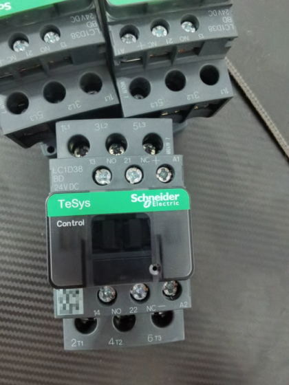
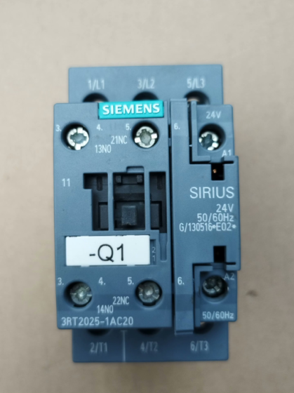
Schneider LC1D38, Siemens 3RT2035, OMRON CJX2-32
- Terminal Definition of S-T35 (Standard 2a2b)
Main Circuit (Incoming top, outgoing bottom)
L1, L2, L3 (Power supply side); T1, T2, T3 (Load side, connected to TH-T35 thermal relay input terminals)
Coil Terminals
A1, A2: AC coil. Two A2 terminals are internally shorted for easy jumper wiring.
Built-in Auxiliary Contacts (2NO+2NC)
✅ Normally Open (NO): 13-14, 43-44
✅ Normally Closed (NC): 21-22, 31-32
Screw size: Main circuit M4; Coil & auxiliary contacts M3.5
- Basic Self-Locking Wiring Diagram (S-T35 + TH-T35 Thermal Relay, Motor Start-Stop)
Main Circuit
3-phase power → Circuit breaker → S-T35 L1/L2/L3 → S-T35 T1/T2/T3 → TH-T35 thermal relay input → Thermal relay output → Motor M
Control Circuit (AC220V example)
- L → Stop button (NC) → Start button (NO) → S-T35 A1
- N → S-T35 A2
- Self-locking: Parallel 13-14 (NO) across the start button
- Overload protection: Wire TH-T35 95-96 (NC) in series into the control circuit; the coil will cut off when overload trips
Full Model List of MS-T Series
1) Non-Reversing Standard Models (S-T, your S-T35 is included)
| Model | AC-3 Current (380V) | Motor Power (380V) | Standard Auxiliary Contacts |
| S-T10 | 11A | 5.5kW | 1a1b |
| S-T12 | 13A | 7.5kW | 1a1b |
| S-T20 | 18A | 7.5kW | 1a1b |
| S-T21 | 21A | 11kW | 2a2b |
| S-T25 | 25A | 11kW | 2a2b |
| S-T32 | 32A | 15kW | 2a2b |
| S-T35 | 35A | 18.5kW | 2a2b |
| S-T50 | 50A | 22kW | 2a2b |
| S-T65 | 65A | 30kW | 2a2b |
| S-T80 | 80A | 37kW | 2a2b |
| S-T100 | 100A | 45kW | 2a2b |
Coil suffix options: AC24V / AC110V / AC220V / AC380V; e.g. S-T35 AC220V
2) Reversing (Forward/Reverse) Integrated Models (S-2×T with built-in interlock)
S-2×T10, S-2×T12, S-2×T20, S-2×T21, S-2×T25, S-2×T32, S-2×T35, S-2×T50, S-2×T65, S-2×T80, S-2×T100
3) Special Derivative Models (Same frame, different structure)
- DC Coil Version (SD-T, not interchangeable with S-T)
SD-T10, SD-T12, SD-T20, SD-T21, SD-T25, SD-T32, SD-T35, SD-T50, SD-T65, SD-T80, SD-T100
- Mechanical Latching Type (SL-T): Pull-in on energization, keep closed after power cut; only released when control circuit is disconnected
SL-T21, SL-T35, SL-T50, SL-T65, SL-T80, SL-T100
- Off-Delay Release Type (S-T□DL)
S-T12DL, S-T21DL, S-T35DL
- Matching Thermal Overload Relays (TH-T Series, frame-matched one-to-one)
TH-T18 (for T10/T12/T20)
TH-T25 (for T21/T25/T32)
TH-T35 (for S-T35)
TH-T50 (for T50)
TH-T65 (for T65/T80)
TH-T100 (for T100)
III. Magnetic Starters (Integrated contactor + thermal relay)
Non-reversing: MSO-T10, MSO-T12, MSO-T20, MSO-T21, MSO-T25, MSO-T32, MSO-T35, MSO-T50, MSO-T65, MSO-T80, MSO-T100
Reversing: MSO-2×T10 …… MSO-2×T100
- Model Naming Rule (S-T□)
S = Contactor
T = MS-T Series (replaces old S-N series)
Numeral = Frame current rating (10/12/20/21/25/32/35/50/65/80/100)
Suffix: Coil voltage (AC220V/AC380V); DL = Off-delay release; SL = Mechanical latch; SD = DC coil
- Cross-Replacement Table with Old S-N Series (Direct Drop-in Replacement)
S-T10 ↔ S-N10
S-T12 ↔ S-N12
S-T20 ↔ S-N20
S-T21 ↔ S-N21
S-T25 ↔ S-N25
S-T32 ↔ S-N32
S-T35 ↔ S-N35 (your model)
S-T50 ↔ S-N50
S-T65 ↔ S-N65
S-T80 ↔ S-N80
S-T100 ↔ S-N100


NH42-63-318x560.png "CHINT PC-type automatic transfer switches (ATS)NH42-63/4SZ")