 Contator,disjuntor,sensor,Codificador,CLP,Conversor

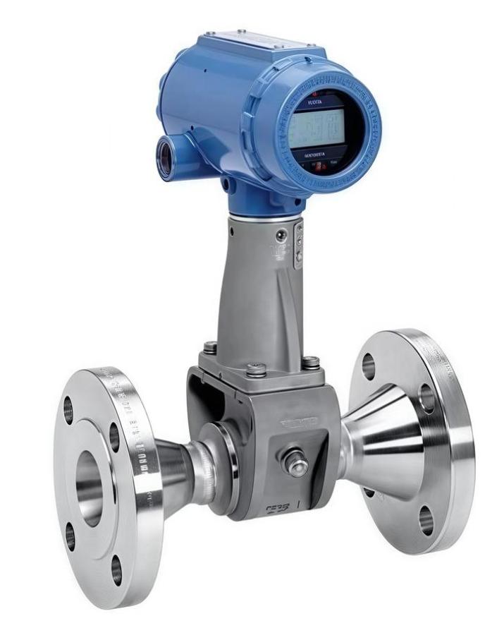
Número completo do modelo: 8800DF010SA1N1D1K8M5Q4
Produto: Medidor de vazão de vórtice flangeado Emerson Rosemount modelo 8800D
Fluidos aplicáveis: Líquidos, gases, vapor saturado e superaquecido.
Decodificação de código de modelo passo a passo
`8800DF 010 S A1 N 1 D 1 K8 M5 Q4`
- 8800D: Série de produtos, corpo do medidor de vazão vórtice
- F: Estilo de conexão flangeada (W = estilo wafer)
- 010: Tamanho nominal 1 polegada / DN25
- S: Material molhado: 316/316L aço inoxidável (CF3M em aço inoxidável fundido)
- A1: Padrão de flange: ASME B16.5 RF Classe 150 (Classe ANSI 150 flange de face elevada)
- N: Versão de temperatura padrão: -40℃ ~ +232 ℃
- 1: Material de habitação: Carcaça de alumínio com 2 × 1/2-14 Entradas de cabo NPT
- D1: Módulo eletrônico: 4–20 mA + Saída analógica HART, sem saída de pulso
- K8: Certificação à prova de explosão: Certificação chinesa (Exd à prova de chamas + Exia intrinsecamente seguro, Certificado CNEX)
- M5: Cabeça do transmissor: Visor digital LCD local
- 4º trimestre: Código de sufixo opcional: Certificação de segurança SIL2 + Diagnóstico Avançado de Processo (Processo Crítico)
Resumo das principais especificações
Diâmetro nominal: DN25 (1″), Flange ANSI Classe 150
Comunicação: 4~20 mA + HART7
Equipado com display LCD local
Proteção contra explosão: Certificação dupla de segurança doméstica à prova de chamas e intrínseca
Nível de integridade de segurança SIL2, adequado para loops de segurança SIS
Mídia mensurável: Vapor, ar comprimido, água e vários fluidos de processo
Vantagens estruturais: Design anti-entupimento totalmente soldado e sem gaxeta; o sensor pode ser substituído on-line sem despressurização ou desligamento da tubulação
Informações Complementares
- Modelo básico comum: 8800DF010SA1N1D1K8M5. O sufixo Q4 é um complemento opcional para certificação SIL e diagnóstico avançado.
- Indústrias típicas: Usinas termelétricas, indústria química, fabricação farmacêutica, Medição de vapor HVAC.
- Lembrete de substituição: Ao selecionar unidades de substituição, diâmetro nominal, classe de pressão do flange, grau à prova de explosão e certificação SIL devem ser totalmente compatíveis.
Dimensões de instalação – Rosemount 8800DF flangeado tipo DN25 (1″, Modelo 8800DF010) ANSI150 RF
Aplicável ao seu modelo: 8800DF010SA1N1D1K8M5Q4 (Medidor de vórtice flangeado DN25 Class150)
> Todos os dados provenientes do documento oficial da Emerson 00813-0106-4004
- Dimensões Gerais Críticas (Unidade: milímetros)
| Parâmetro | DN25 1″ Classe 150 RF (8800DF010 A1) | Observações |
| Dimensão presencial (UM) | 165 milímetros | Dimensão de instalação principal (comprimento entre as faces de vedação do flange) |
| Diâmetro externo do flange DE | 165 milímetros | Flange padrão ASME B16.5 Class150 de 1 polegada |
| Diâmetro do círculo do parafuso | 120.7 milímetros | |
| Quantidade & tamanho dos furos dos parafusos | 8 ×M16 (5/8″) | |
| Espessura do flange | 29.2 milímetros | |
| Altura total do transmissor (centro do flange até o topo da tela) | ≈240~255mm | Cabeça do transmissor giratória em 0°/90°/180° |
| Entrada de cabo | 2 × 1/2 TNP (código de habitação 1 conforme sua configuração) | |
| Diâmetro externo máximo do corpo do medidor | 95 milímetros | |
| Peso líquido aproximado | ≈7,3kg | Versão com display LCD |
> ⚠️ Distinção importante: 8800DW = tipo de wafer; 8800DF = tipo flangeado. Seus comprimentos face a face diferem completamente e não podem ser trocados.
- Requisitos de tubo reto (Obrigatório para medir a precisão, D=DN25)
- A montante, sem distúrbios de fluxo (tubo reto sem válvulas ou cotovelos): ≥10D (≥250mm)
- A jusante (requisito universal): ≥5D (≥125mm)
- Cotovelo único de 90° no plano a montante: ≥20D
- Dois cotovelos de 90° fora do plano a montante: ≥30D
- As válvulas de controle devem ser instaladas a jusante do medidor de vazão. Se as válvulas forem instaladas a montante, comprimento do tubo reto a montante ≥50D.
- Diretrizes de orientação de instalação (Vapor / Líquido / Serviço de gás)
- Medição de vapor saturado (condição de trabalho mais comum)
Arranjo preferido: Pipeline horizontal, cabeça do transmissor montada horizontalmente lateralmente (evita que o condensado flua para o suporte do sensor)
NÃO monte a cabeça do transmissor verticalmente para baixo
- Serviço líquido
Instalação horizontal recomendada. Para tubulação vertical, o fluido deve fluir apenas para cima. O fluxo descendente é proibido (risco de aprisionamento de gás e enchimento incompleto da tubulação)
Evite a instalação em pontos altos da tubulação (acumulação de gás)
- Serviço de gás
Instalação horizontal ou vertical ascendente preferida; evite pontos baixos onde o líquido pode se acumular
- Proibições estritas de instalação
- O isolamento térmico não deve cobrir a seção inferior do suporte do transmissor para evitar superaquecimento dos componentes eletrônicos (temperatura ambiente máxima: 85℃).
- As juntas de flange não devem penetrar no furo da tubulação durante a montagem.
- A tubulação a montante e a jusante deve ser concêntrica; o desalinhamento deve ser menor que 0.5 milímetros.
- Mantenha-se afastado de fontes de vibração fortes, como bombas e compressores alternativos. Se a vibração for inevitável, instale suportes de tubulação em 2D a montante e a jusante.
- O corpo do 8800D não vem com um condicionador de fluxo integrado. Instale um condicionador de fluxo de tubulação se não for possível fornecer tubo reto suficiente.
- Referência rápida para comprimento face a face (Classe Flangeada 150) para outros tamanhos
DN15(005): 140 milímetros
DN25(010): 165 milímetros (seu modelo)
DN40(015): 178 milímetros
DN50(020): 203 milímetros

