 Contator,disjuntor,inversor solar,medidor elétrico,baterias solares

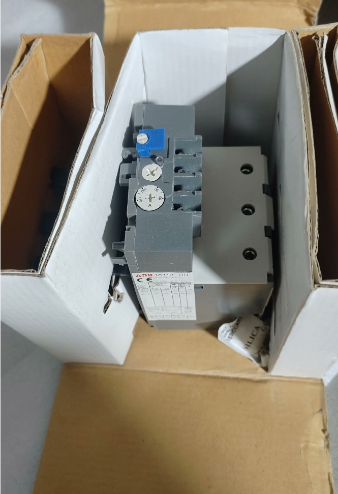

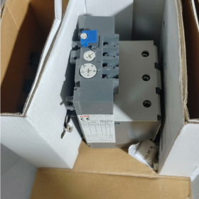
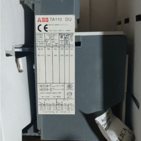
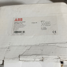
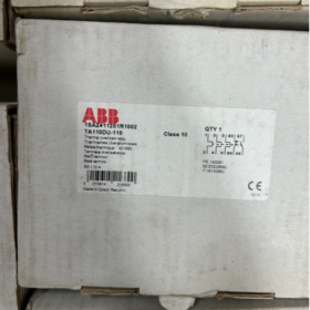
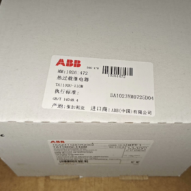
O TA110DU110 é um clássico de 3 pólos relé de sobrecarga térmica de ABB TA series, fornecendo proteção integrada para motores assíncronos trifásicos com faixa de corrente nominal de 80~110A. Adotando o princípio de disparo em tempo inverso de tiras bimetálicas, este relé vem de fábrica com proteção contra perda de fase e compensação automática de temperatura ambiente, com uma classe de viagem da Classe 10A. Ele pode ser conectado diretamente aos contatores da série ABB A/AE/AF95~110 ou montado de forma independente em trilhos DIN. Equipado com modos de reinicialização manual/automática selecionáveis e um modo normalmente aberto (NÃO) mais um normalmente fechado (NC) contato de sinal auxiliar, serve como um componente de proteção padrão para circuitos de controle de motores industriais. Amplamente aplicado a cargas de energia, como ventiladores, bombas de água, compressores e linhas transportadoras, evita efetivamente acidentes de queima de enrolamento de motores causados por sobrecarga, rotor bloqueado e perda de fase.
Modelo Completo: `TA110DU110`
- ENFRENTANDO: Código de série geral para relés de sobrecarga térmica ABB, representando a família de relés de proteção eletrotérmicos
- 110: Classificação atual do quadro, indicando a corrente nominal máxima do quadro de 110A para este produto
- DE: Código do tipo de função, representando especificação padrão com proteção de 3 pólos, detecção de perda de fase, compensação de temperatura ambiente e montagem direta em contatores
- 110: Limite superior da configuração atual, correspondendo a uma faixa de corrente ajustável de 80A ~ 110A
Especificações Técnicas Principais
| Categoria de parâmetro | Item de parâmetro | Especificação detalhada |
| Características do Circuito Principal | Tensão nominal de isolamento Ui | 690V e / 440Em DC |
| Tensão operacional nominal UL/CSA | 600V e | |
| Faixa de corrente ajustável | Ajustável continuamente de 80A a 110A | |
| Classe de viagem | Classe 10A (classe de proteção de motor padrão) | |
| Número de poloneses | 3 postes, proteção completa de 3 pólos | |
| Proteção contra perda de fase | Padrão integrado; acelera o disparo sob desequilíbrio trifásico | |
| Compensação de temperatura | Suportado; a precisão da proteção permanece inalterada dentro de -25°C ~ +55°C de temperatura ambiente | |
| Contatos Auxiliares | Configuração de contato | 1 NÃO + 1 NC, isolado eletricamente |
| Corrente Térmica Convencional Ith | 5UM | |
| Capacidade nominal de contato | AC250V 3A; DC24V 5A | |
| Mecânico & Montagem | Método de montagem | Montagem direta em contatores / montagem independente em trilho DIN |
| Contatores compatíveis | Série A95, A110, AE95, AE110, AF95, AF110 | |
| Método de fiação | Terminais de fixação por parafuso | |
| Peso total | Aprox.. 0.76kg | |
| Modo de reinicialização | Redefinição manual/automática comutável; suporta expansão de reinicialização remota | |
| Ambiente & Certificações | Temperatura ambiente operacional | -25℃ ~ +55℃ |
| Temperatura de armazenamento | -40℃ ~ +70 ℃ | |
| Classificação de proteção de entrada | IP20 | |
| Certificações de Conformidade | CE, UL, CSA, CCC, GL (Certificação Marinha Germanischer Lloyd) | |
| Padrões em conformidade | CEI 60947-4-1, EM 60947-4-1 |
Referência Cruzada de Modelos dentro da Mesma Série
- Especificações completas do quadro TA110DU
| Modelo Completo | Faixa de corrente ajustável | Potência do motor compatível (380V) | Contatores correspondentes |
| TA110DU-65 | 50 ~65A | 30kW | A95/AE95/AF95 |
| TA110DU-80 | 60 ~ 80A | 37kW | A95/AE95/AF95 |
| TA110DU-90 | 66 ~90A | 45kW | A110/AE110/AF110 |
| TA110DU-110 | 80 ~ 110A | 55kW | A110/AE110/AF110 |
- Comparação de séries de quadros adjacentes
| Modelo de série | Corrente nominal do quadro | Corrente Máxima Ajustável | Cenários Aplicáveis |
| TA110DU | 110UM | 110UM | Médio & motores de pequena potência (30~55kW) |
| TA200DU | 200UM | 200UM | Médio & motores de grande potência (75~110kW) |
| TA450DU | 450UM | 450UM | Motores de alta potência para serviços pesados (132~250kW) |
Cenários típicos de aplicação
- Circuito de proteção de partida de motor padrão: Combinado com contatores da série ABB A/AF para formar partidas eletromagnéticas, conectado em série ao circuito principal de motores trifásicos para obter proteção contra sobrecarga do motor, rotor bloqueado e perda de fase. É a solução de proteção padrão para equipamentos de energia em geral, incluindo ventiladores, bombas de água, compressores de ar e fusos de máquinas-ferramenta.
- Centros de controle de motores MCC: Serviram como unidades de proteção padrão para circuitos alimentadores de motores em armários de gavetas e armários fixos, integrado com contatores para realizar controle e proteção integrados de partida e parada do motor.
- Transportador & Sistemas de classificação logística: Combinado com motores de rolos e motores de acionamento de classificação, adaptando-se às condições de trabalho freqüentes de start-stop e flutuação de carga das linhas de produção, e prevenção do envelhecimento do motor e desgaste causado por sobrecarga de longo prazo.
- Ar Condicionado Central & Unidades de refrigeração: Proteja equipamentos de refrigeração, como compressores e ventiladores de torres de resfriamento, adequado às características da indústria de refrigeração de flutuações severas de carga e operação sazonal de alta carga.
- Suporte para equipamentos completos OEM: Amplamente compatível com máquinas industriais, incluindo máquinas de embalagem, borracha & máquinas plásticas e equipamentos auxiliares metalúrgicos. Como componentes padronizados de proteção do motor, atende aos requisitos de especificação de segurança elétrica para entrega na fábrica de equipamentos.
Matriz de solução de problemas comuns
| Fenômeno de falha | Análise de causa raiz | Soluções passo a passo |
| O relé desarma falsamente durante a operação normal do motor | 1. Valor de configuração de corrente baixo, inferior à corrente nominal do motor | 1. Verifique a corrente nominal do motor e ajuste o botão de configuração para o valor nominal correspondente |
| 2. Temperatura ambiente excessivamente alta, excedendo a faixa de compensação | 2. Melhore a dissipação de calor do gabinete e evite luz solar direta ou radiação de fonte de calor | |
| 3. Desvio severo de corrente induzido por desequilíbrio de tensão trifásico | 3. Meça correntes trifásicas para solucionar riscos ocultos de desequilíbrio de tensão ou perda de fase | |
| 4. Tempo de partida do motor muito longo, excedendo o limite de resistência da classe 10 aula de viagem | 4. Substitua por relés de sobrecarga térmica da classe 20 ou Classe 30 para aplicativos de inicialização de carga pesada | |
| O relé não desarma sob sobrecarga do motor ou rotor bloqueado | 1. Valor de configuração de corrente excessivamente alto, muito maior que a corrente nominal do motor | 1. Recalibre o valor de configuração para corresponder estritamente à corrente nominal do motor |
| 2. Terminais soltos da fiação do circuito principal, causando resistência de contato excessiva | 2. Aperte os terminais do circuito principal e solucione problemas de superaquecimento & problemas de oxidação | |
| 3. Mecanismo mecânico do relé preso e falha no conjunto de disparo | 3. Corte a energia e teste manualmente a flexibilidade do mecanismo de disparo; substitua o módulo se ocorrer obstrução | |
| A proteção não é ativada em caso de falta de perda de fase | 1. Fiação de entrada trifásica errada com conexão incompleta ao circuito principal do relé | 1. Verifique a fiação trifásica L1/L2/L3 para garantir que todas as fases estejam conectadas de forma confiável |
| 2. Envelhecimento e falha de componentes bimetálicos internos | 2. Simule artificialmente a perda de fase para testar a função de proteção; substitua o relé se a função falhar | |
| Saída anormal ou nenhuma saída de sinais de contato auxiliar | 1. A carga de contato auxiliar excede a capacidade nominal, resultando em esgotamento de contato | 1. Confirme se a corrente de carga não excede a classificação do contato; adicione relés intermediários para amplificação de corrente, se necessário |
| 2. Sem reinicialização após tropeçar, os contatos permanecem em estado de falha | 2. Reinicialize o relé manual ou automaticamente após solucionar as causas da falha raiz | |
| 3. Mau contato devido à oxidação do contato | 3. Meça a resistência liga-desliga do contato; substitua o módulo se houver mau contato |
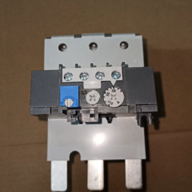
- Definição de terminal & Descrição da função
O TA110DU110 adota regras de numeração de terminais padrão da indústria, dividido em duas partes: circuito de alimentação principal e circuito de controle auxiliar. Todos os terminais são do tipo braçadeira de parafuso montados na frente, com todas as operações de fiação acessíveis pela parte frontal.
- Terminais do Circuito Principal (Circuito de Potência Trifásico)
| Marca terminal | Tipo de terminal | Instruções de fiação |
| 1L1, 3L2, 5L3 | Terminais de entrada | Entrada do lado superior, conectado aos terminais de saída dos contatos principais do contator, correspondente à alimentação trifásica L1/L2/L3 |
| 2T1, 4T2, 6T3 | Terminais de saída | Saída do lado inferior, conectado diretamente aos enrolamentos do estator de motores assíncronos trifásicos |
Notas: O circuito principal trifásico não tem exigência de polaridade, ainda assim, cada fase deve ser conectada em correspondência um-a-um, sem desconexão entre fases cruzadas. Quando montado diretamente em contatores, o circuito principal é conduzido automaticamente através de barras de cobre plugáveis, sem necessidade de fiação de energia extra.
- Terminais de Circuito Auxiliar (Controlar & Circuito de Sinal)
| Marca terminal | Tipo de contato | Descrição da função | Finalidade típica da fiação |
| 95 – 96 | Normalmente fechado (NC) | Condutivo em condições normais de operação; abre em caso de disparo causado por sobrecarga/perda de fase | Conectado em série ao circuito de controle da bobina do contator para cortar a alimentação do contator e parar o motor em caso de falhas |
| 97 – 98 | Normalmente aberto (NÃO) | Desconectado em condições normais de operação; fecha em caso de disparo causado por sobrecarga/perda de fase | Conectado a circuitos de alarme de luz sonora ou pontos de entrada digital PLC para upload de sinais de falha e notificação de alarme |
Os contatos auxiliares são isolados eletricamente sem conexão elétrica ao circuito principal e corrente térmica convencional de 5A. Relés intermediários são recomendados para conexão em série para expandir a capacidade e evitar queima de contato ao controlar cargas de alta potência.
- Esquemas de fiação típicos
- Fiação de montagem direta no contator (Mais comumente usado)
Este é o método de aplicação padrão para TA110DU110. Ele é conectado diretamente na parte superior dos contatores da série ABB A95/A110/AF95/AF110. O circuito principal é conectado automaticamente através de conectores plug-in internos, com apenas o circuito de controle exigindo fiação externa:
- A energia trifásica passa através de um disjuntor e se conecta aos terminais de entrada principais L1/L2/L3 do contator
- Após o relé de sobrecarga térmica ser montado diretamente no contator, o circuito principal é conduzido automaticamente sem fiação de energia extra
- Uma extremidade da fonte de alimentação de controle passa pelos botões de parada e partida e se conecta ao terminal A1 da bobina do contator
- O 95-96 O contato NF do relé térmico é conectado em série ao fio energizado do circuito da bobina do contator para realizar o desligamento automático do motor sob sobrecarga
- O 97-98 O contato NO do relé térmico está em paralelo com luzes indicadoras de falha ou conectado aos pontos DI do PLC para alarme de falha
- Fiação de montagem em trilho DIN independente
A montagem independente em trilho é adotada para instalação separada ou combinação com contatores de outras marcas:
- Os terminais de saída do contator L1/L2/L3 são conectados aos terminais de entrada do relé térmico 1L1/3L2/5L3 por meio de cabos de alimentação
- Terminais de saída do relé térmico 2T1/4T2/6T3 conectados aos terminais trifásicos do motor
- O circuito de controle segue a mesma lógica de fiação do esquema de montagem direta, com o 95-96 Contato NF conectado em série no circuito da bobina do contator
Precauções com fiação:
A área da seção transversal dos cabos do circuito principal deve corresponder à corrente nominal de 110A; 25cabos de cobre mm² são recomendados
1Cabos de controle de aproximadamente 1,5 mm² são sugeridos para circuitos de controle auxiliares
O aterramento confiável é obrigatório para garantir a segurança pessoal e do equipamento
III. Tabela de comparação de parâmetros de modelos equivalentes entre marcas
Abaixo está uma comparação de parâmetros dos principais relés de sobrecarga térmica da mesma faixa de corrente da Siemens e Schneider Electric, para referência durante a seleção alternativa:
| Item de comparação | ABB | Schneider Elétrica | Siemens |
| Modelo Completo | TA110DU110 | LRD3365C | 3RU5146-4MB1 |
| Faixa de corrente ajustável | 80 ~ 110A | 80 ~ 104A | 80 ~ 100A |
| Corrente nominal do quadro | 110UM | 115UM | 140UM |
| Classe de viagem | Classe 10A | Aula 10 | Aula 10 |
| Número de poloneses | 3 postes | 3 postes | 3 postes |
| Configuração de contato auxiliar | 1NÃO + 1NC (isolado eletricamente) | 1NÃO + 1NC (isolado eletricamente) | 1NÃO + 1NC (isolado eletricamente) |
| Proteção contra perda de fase | Padrão integrado | Padrão integrado | Padrão integrado |
| Compensação de temperatura ambiente | Suportado (-25℃~+55℃) | Suportado (-20℃~+60℃) | Suportado (-20℃~+60℃) |
| Modo de reinicialização | Comutável manual/automático | Comutável manual/automático | Comutável manual/automático |
| Série de contatores compatíveis | A95~A110, AF95~AF110 | LC1D95~LC1D115 | 3RT5045~3RT5046 |
| Método de montagem | Montagem direta no contator / Trilho DIN | Montagem direta no contator / Trilho DIN | Montagem direta no contator / Trilho DIN |
| Certificações de Conformidade | CE, UL, CCC, GL | CE, UL, CCC | CE, UL, CCC |


 Controlador de temperatura de selagem térmica por impulso")


")


NH42-63-318x560.png "Chaves de transferência automática tipo PC CHINT (ATS)NH42-63/4SZ")


