 Contator,disjuntor,sensor,Codificador,CLP,Conversor


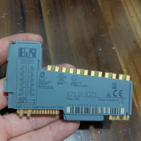
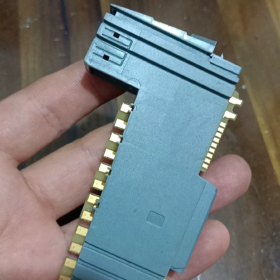
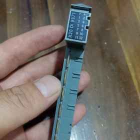
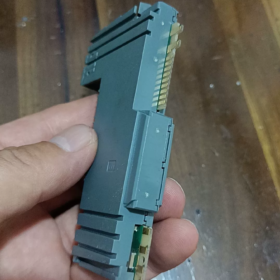
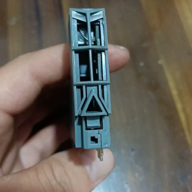
Explicação do código do modelo
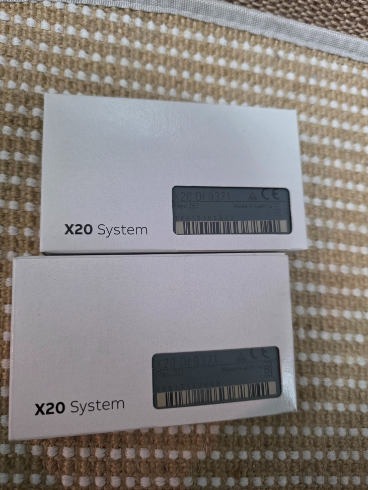
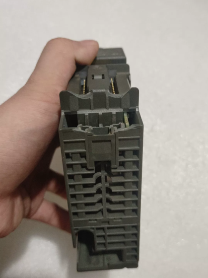
X20DI9371
X20: X20 distributed I/O system platform
DE: Entrada Digital
9371: Código de especificação do módulo
- Main Electrical & Hardware Specifications
| Item | Especificação |
| Número de canais | 16 entradas digitais |
| Tipo de entrada | 24 VDC sinking / fornecimento compatível, CEI 61131-2 Tipo 3 |
| Tensão de entrada nominal | 24 CCV (faixa de operação: 18~30 VCC) |
| Impedância de entrada | Aprox.. 3.9 kΩ |
| Logic ON (1) Limite | ≥11 VCC |
| Logic OFF (0) Limite | ≤5 VCC |
| Input Current per Channel | ≈6 mA @24 VDC |
| Atraso de resposta | Típico 0.1 EM; configurable hardware filter: 0.1 / 0.5 / 3 / 15 EM (parameter setting via software) |
| Método de isolamento | Isolamento de grupo: 4 canais por grupo, total 4 grupos isolados |
| Isolation voltage between groups: 500 VAC | |
| Interface de ônibus | X20 Link internal system bus |
| Indicação de status | Independent LED for each channel; module power LED |
| Consumo de energia | Typ. 1.8 C |
- Mecânico & Especificações Ambientais
Montagem: Padrão 35 mm trilho DIN, instalação horizontal
Dimensões: C 40 mm × H 100 mm × D 76.5 milímetros
Temperatura operacional: -20 ℃~ +60 ℃ (inside control cabinet)
Armazenar / Temperatura de Transporte: -40 ℃~ +85 ℃
Classe de Proteção: IP20 (apenas para instalação em gabinete)
Certificações: CE, UL 508, GL marine certification, compatível com EN 61000 EMC industrial standards
- Estrutura Interna & Definição de terminal
16 canais divididos em 4 grupos isolados:
Grupo1: CH0~CH3
Grupo2: CH4~CH7
Group3: CH8~CH11
Group4: CH12~CH15
⚠️ Important Wiring Rule: O terminal comum de um grupo isolado deve compartilhar o mesmo 24 Polaridade V; NÃO conecte separadamente, não referenciado 24 Fontes de alimentação V para diferentes grupos isolados, caso contrário, a diferença de potencial pode danificar o circuito de isolamento.
Configurações de fiação
- Fonte de entrada (PNP Sensor)
A saída do sensor se conecta ao terminal DI do módulo; terminais comuns do módulo conectados a 0V(GND)
- Entrada afundando (Sensor NPN)
O terminal de alimentação do sensor se conecta a 24V+, saída do sensor para o terminal DI; terminais comuns do módulo conectam a +24V
- Princípio Operacional
Sinal do sensor digital externo → Circuito de filtro de hardware RC frontal → Grupo de isolamento do optoacoplador → Circuito de modelagem de sinal → Chip de comunicação de barramento X20
O controlador lê ciclicamente o status do canal através da CPU X2X/X20. Os parâmetros de tempo de filtro podem ser configurados no Automation Studio para suprimir saltos de contato e pulsos de interferência gerados pelos inversores.
- Informações de software
Software de programação: Estúdio de Automação 4.0 e todas as versões posteriores suportadas
Identificação de hardware: Biblioteca integrada de descrição do dispositivo X20 padrão, nenhum arquivo GSD extra necessário
Imagem do processo: Mapeamento automático de endereço de canal; forçar sinal de suporte & monitoramento de sinal on-line
Funções suportadas: Diagnóstico de canal (sem detecção de quebra de fio, X20DI9371 não suporta diagnóstico de quebra de fio)
- Comparação de modelos & Substituição compatível
Comparação com modelos semelhantes da série X20
| Modelo | Canais | Recurso de isolamento | Características |
| X20DI9371 | 16DE | 4 canais por grupo isolado | Módulo padrão de uso geral, amplamente utilizado em projetos |
| X20DI9372 | 16DE | Isolamento galvânico individual de canal completo | Para ambientes de alta interferência, multi-sinais com diferentes potenciais |
| X20DI4371 | 4DE | 4 canais por grupo isolado | Módulo compacto para pontos de E/S limitados |
✅ Condições de substituição direta
Se X20DI9371 for usado em projetos existentes:
Atualização para maior desempenho anti-interferência: X20DI9372 (atribuição de pinos compatível, nenhuma modificação do programa necessária, fiação totalmente intercambiável; a única diferença é o desempenho de isolamento aprimorado)
❌ Não diretamente intercambiável: X20DI4371 possui diferentes quantidades de canais e layout de terminal da unidade base
- Cenários típicos de aplicação
Máquinas-ferramentas, máquinas de embalagem, transportadores de manuseio de materiais, borracha & equipamento de plástico, tratamento de água, linhas de produção de automação geral
Aquisição de sinal: Interruptores de proximidade, sensores fotoelétricos, interruptores de limite, botões, contatos de relé passivos
- Diretrizes de instalação & Solução de problemas
Proibições estritas
- Nunca aplique tensão superior a 30 CCV, danificará permanentemente os circuitos de entrada
- Não conecte dois pontos de aterramento não comuns 24 Fontes de alimentação V para diferentes grupos isolados
- Evite roteamento paralelo de cabos de sinal e cabos de alimentação (forte interferência elétrica leva a sinais tremeluzentes)
Falhas Comuns
- LED do canal sempre ligado: Fio de sinal em curto-circuito com o terra; fonte de alimentação anormal para sensor PNP
- Flutuação intermitente de sinal: Interferência eletromagnética severa → aumenta o tempo de filtro de hardware; verifique a blindagem & aterramento
- Todos os canais em um grupo sem sinal: Perda de alimentação para o terminal comum do grupo correspondente
- Unidades Base Compatíveis
Base padrão: X20BM01 (base terminal de parafuso)
Base opcional: X20BM11 (terminal de conexão rápida de gaiola de mola)
A base deve ser encomendada separadamente; base terminal NÃO está incluída com o módulo!
Atribuição do pino do terminal X20DI9371
Base Compatível: X20BM01 (parafuso) / X20BM11 (terminal de mola)
16 canais divididos em 4 grupos galvanicamente isolados (4 canais cada)
Grupo1: CH0~CH3|Grupo2: CH4~CH7|Grupo3: CH8~CH11|Grupo4: CH12~CH15
Sequência Terminal (De cima para baixo na base)
Grupo 1 (CH0~CH3)
1: DI0
2: DI1
3: ED2
4: DI3
5: COM0 (Terminal comum para Grupo1)
Grupo 2 (CH4~CH7)
6: DI4
7: DI5
8: DI6
9: DI7
10: COM1 (Terminal comum para Grupo2)
Grupo 3 (CH8~CH11)
11: DI8
12: DI9
13: DI10
14: DI11
15: COM2 (Terminal comum para Grupo3)
Grupo 4 (CH12~CH15)
16: DI12
17: DI13
18: DI14
19: DI15
20: COM3 (Terminal comum para Grupo4)
Recapitulação das especificações de fiação
- Sensor PNP (Fonte de entrada, Padrão da Indústria)
Todos COM0/COM1/COM2/COM3 → conectar-se a 24 VCC 0V(GND)
Fio de sinal do sensor para DIx, terminal positivo do sensor para 24V+
- Sensor NPN (Entrada afundando)
Todos COM0/COM1/COM2/COM3 → conectar-se a +24 CCV
Fio de sinal do sensor para DIx, terminal negativo do sensor para 0V
⚠️ Importante: COM0/COM1/COM2/COM3 são isolados galvanicamente um do outro.
Não conecte terminais COM diferentes a fontes de alimentação com potencial de aterramento não compartilhado!
Etapas para configurar o filtro de entrada no Automation Studio
- Localize X20DI9371 na árvore do projeto e clique duas vezes para abrir a janela de configuração
- Nome do parâmetro: Tempo de filtro de entrada
Opções selecionáveis:
0.1 EM (resposta rápida, para sinais de alta velocidade)
0.5 EM
3 EM (recomendado para botões normais & interruptores de proximidade)
15 EM (ambiente de interferência pesada, suprimir o salto do contato)
- Baixar projeto; os parâmetros entram em vigor imediatamente sem desligar e ligar a energia



NH42-63-318x560.png "Chaves de transferência automática tipo PC CHINT (ATS)NH42-63/4SZ")



