 Contator,disjuntor,sensor,Codificador,CLP,Conversor


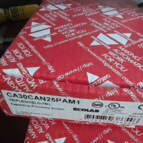
Detalhamento do código do modelo
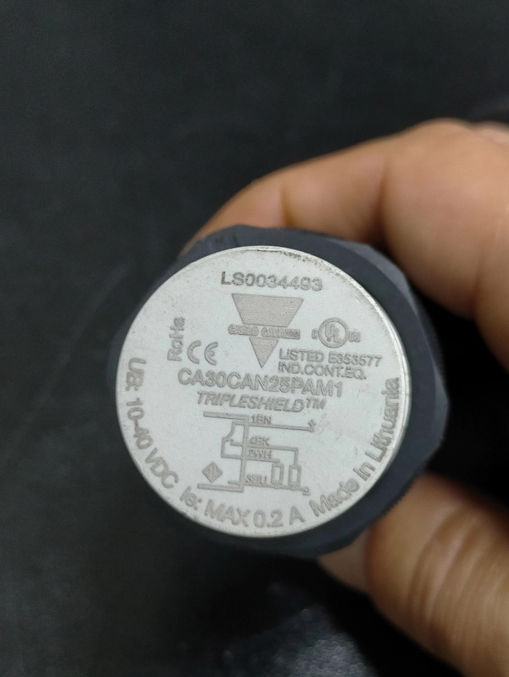
CA30CAN25PAM1
- CA: Sensor de proximidade capacitivo série
- 30: Carcaça roscada cilíndrica M30
- PODE: Não blindado (montagem não embutida); CAF = Blindado (montável embutido)
- 25: Distância de detecção nominal: 25 milímetros
- P: Saída PNP
- UM: Saída dupla com NÃO + NC (1 normalmente aberto, 1 normalmente fechado)
- M1: Conector macho M12 de 4 pinos (sufixo da versão do cabo: PA)
- Especificações elétricas principais
| Parâmetro | Especificação |
| Tensão de alimentação | 10~40 VCC (incluindo ondulação) |
| Tipo de saída | PNP, 4-fio com NÃO (Normalmente aberto) + NC (Normalmente fechado) |
| Corrente de carga | Máx.. 200 mA por canal |
| Frequência de comutação | 50 Hz |
| Tempo de resposta | ≤ 10 EM |
| Faixa de histerese | 3%~20% da distância de detecção nominal |
| Corrente sem carga | ≤ 12 mA |
| Corrente de fuga fora do estado | ≤ 100 µA |
| Funções de proteção | Proteção total contra polaridade reversa, curto-circuito e surtos transitórios |
| Ajuste de sensibilidade | Potenciômetro multivoltas (11 voltas elétricas / 16 voltas mecânicas), ajustável de 4 mm para 30 milímetros |
- Mecânico & Especificações Ambientais
Habitação: 30% poliéster PBT reforçado com fibra de vidro, linha M30 cinza claro
Proteção de entrada: IP67 / IP68 / IP69K, capacidade de lavagem de alta pressão (Certificado de qualidade alimentar ECOLAB)
Temperatura operacional: -30℃ ~ +85℃
Temperatura de armazenamento: -40℃ ~ +85℃
Peso: Aprox.. 110 g
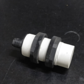
Montagem: Não blindado; a cabeça de detecção deve se projetar para fora, não pode ser embutido em montagens de metal
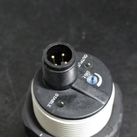
- Definição do indicador LED
- LED verde: Constante para energia estável; pisca para acúmulo de poeira ou alarme de falha de superaquecimento
- LED amarelo: Indicador de status de saída (acende quando o alvo é detectado)
- Atribuição de pinos M12 de 4 pinos (Padrão Masculino)
- Alfinete 1 (Marrom): DC24V Positivo (+)
- Alfinete 2 (Branco): Sinal NC normalmente fechado
- Alfinete 3 (Azul): 0V GND Negativo (-)
- Alfinete 4 (Preto): NENHUM sinal normalmente aberto
- Principais vantagens técnicas
- 4Tecnologia de blindagem tripla TRIPLESHIELD™ de ª geração
Imunidade superior à interferência EMI de inversores de frequência variável e servomotores, adequado para instalação perto de gabinetes de controle do inversor.
- Temperatura Automática & Compensação de umidade
O limite de detecção não varia sob temperaturas extremas ou acúmulo de poeira, garantindo um desempenho estável a longo prazo.
- Alarme de falha integrado
O LED verde pisca quando ocorre sobrecarga de poeira ou limite de temperatura, fornecendo aviso antecipado de falha potencial.
- Ampla compatibilidade de mídia
Detecta metais, plásticos, madeira, papel, líquidos e materiais granulares; amplamente utilizado para nível de material e detecção de presença.
- Cenários típicos de aplicação
- Detecção de nível de grânulos e pós em silos / tremonhas
- Verificação de presença de caixas e peças plásticas em máquinas de embalagem
- Contagem de materiais em estações de lavagem de máquinas de processamento de alimentos
- Alarme de escassez de matéria-prima para equipamentos de moldagem por injeção e extrusão
- Detecção de posição de peças não metálicas
- Comparação de seleção entre séries
| Modelo | Tipo de montagem | Distância de detecção | Saída | Estilo de fiação |
| CA30CAN25PAM1 | M30 não blindado | 25 milímetros | PNP NÃO+NC | Plugue M12 |
| CA30CAN25PA | M30 não blindado | 25 milímetros | PNP NÃO+NC | 2m cabo fixo |
| CA30CAN25NAM1 | M30 não blindado | 25 milímetros | NPN NÃO+NC | Plugue M12 |
| CA30CAF16PAM1 | Descarga blindada M30 | 16 milímetros | PNP NÃO+NC | Plugue M12 |
- Proibições de montagem
- Não incorpore totalmente o sensor em suportes de metal; isso reduz drasticamente a distância de detecção ou causa mau funcionamento completo.
- Evite superfícies metálicas de grandes áreas dentro 30 mm ao redor da face de detecção.
- Reduza a sensibilidade ao detectar meios com alto dielétrico (água, PVC) para evitar falsos disparos.
- Os conectores M12 com classificação IP69K devem ser compatíveis com ambientes de lavagem.
- Referência de modelo alternativo
Alternativas Domésticas: M30 não blindado 25 mm PNP NO+NC sensor de proximidade capacitivo (por exemplo. Schneider XX30B1PA10M12, Omron E2K-C30MT1)
Modelo de descarga de curta distância da mesma marca: CA30CAF16PAM1 (16 versão blindada mm)
Princípio de funcionamento do sensor de proximidade capacitivo Carlo Gavazzi CA30CAN25PAM1
- Categoria Básica: Sensoriamento Capacitivo (Distinto de sensores indutivos)
Este modelo adota um circuito de oscilação capacitiva de alta frequência AC. Em vez de detectar correntes parasitas em metal, mede mudanças na constante dielétrica. Ele pode detectar metais, plásticos, água, papel, madeira e pós granulares.
Composição do Circuito Central Interno
- Loop de oscilação LC de alta frequência (circuito ressonante formado pelo eletrodo de detecção e capacitor interno)
- Detecção de amplitude & circuito de comparação
- Módulo de compensação de temperatura e condicionamento de sinal
- Driver de saída PNP e circuito de alarme de falha
- Fluxo de trabalho operacional completo
- Estado de oscilação de referência descarregado
Uma capacitância fixa \(C_0\) se forma entre a superfície de detecção de metal frontal e o solo. O circuito LC interno gera continuamente oscilação de alta frequência (Faixa de MHz) com amplitude e frequência fixas. Os juízes do circuito “nenhum material / sem alvo” e mantém o estado de saída original.
- Abordagens alvo & Mudanças de capacitância equivalente
O ar tem uma constante dielétrica ε ≈ 1; plásticos, água, madeira e metais apresentam constantes dielétricas muito mais altas.
Quando o alvo medido se aproxima da face de detecção, o meio alvo preenche o espaço entre o eletrodo e o terra, aumentando a capacitância equivalente global \(C\):
\[C=\frac{\varepsilon S}{4\pi kd}\]
A distância reduzida d e o aumento da constante dielétrica ε levam a uma maior capacitância total.
- A atenuação da amplitude de oscilação aciona a ação do interruptor
Mudanças de frequência ressonante LC com capacitância, aumentando a perda de energia no circuito de oscilação e diminuindo significativamente a amplitude de oscilação.
O chip de detecção interno compara continuamente a amplitude do sinal com um limite de referência predefinido. Quando a amplitude cai abaixo do limite, o sistema confirma “alvo detectado”, o LED de saída amarelo acende, e o sinal PNP muda de estado.
- Retração alvo & Recuperação de capacitância
Depois que o alvo sai da zona de detecção, o meio reverte para ar, capacitância retorna à linha de base inicial, oscilação restaura sua amplitude original, e o sensor reinicia.
- Lógica de detecção especial para alvos metálicos
Os metais formam diretamente a capacitância de acoplamento com o eletrodo de detecção enquanto protegem o campo elétrico, gerando uma variação de capacitância muito maior.
Em distâncias idênticas, classificação de sensibilidade de detecção: Metal Aterrado > Água/Líquido > Plástico PVC > Madeira Seca. O potenciômetro multivoltas na cauda do sensor ajusta o limite de detecção para combinar com diferentes materiais.
- Tecnologia exclusiva do modelo: Princípio Anti-Interferência da Blindagem Tripla TRIPLESHIELD
O CA30CAN25PAM1 integra uma estrutura de blindagem de três camadas, a principal tecnologia proprietária dos sensores capacitivos Carlo Gavazzi:
- Escudo de sinal interno: Envolve o eletrodo de detecção para bloquear EMI de alta frequência de cabos externos, inversores e servoacionamentos, evitando falsa atenuação e falso disparo do circuito de oscilação.
- Camada de compensação de temperatura: Termistores integrados corrigem o desvio de temperatura em tempo real, calibrando automaticamente a capacitância da linha de base sob condições extremas de calor/frio para estabilizar a distância de detecção.
- Escudo Terrestre da Habitação: O invólucro metálico roscado M30 pode ser aterrado para bloquear a interferência do campo elétrico de frequência de potência de gabinetes e motores.
- Princípio da Histerese (Função anti-vibração)
O circuito possui uma banda de histerese fixa (3%~20% da distância de detecção nominal):
Distância de ativação (alvo se aproximando) ≠ Redefinir distância (alvo recuando)
Elimina a troca frequente de saída causada por pequenas vibrações do material ou leve adesão de poeira, estabilização do monitoramento do nível de material e contagem de peças.
- Diferenças principais vs.. Sensores de proximidade indutivos
| Recurso | Sensor capacitivo CA30CAN25PAM1 | Sensor de proximidade indutivo padrão |
| Princípio de detecção | Variação da constante dielétrica + atenuação de oscilação capacitiva | Perda de corrente parasita de metal |
| Objetos detectáveis | Metais, plásticos, água, pó, madeira, papel | Apenas metais condutores |
| Distância de detecção | Até 25 mm para tipo M30 não blindado | Normalmente ≤15 mm para sensores indutivos M30 |
| Aplicações Típicas | Detecção de nível de material, verificação de presença não metálica, detecção de líquido | Posicionamento de peças metálicas |
- Princípios-chave do falso acionamento (Causa raiz das restrições de montagem)
- Este modelo CAN não blindado não pode ser embutido em metal: o metal ao redor da face de detecção altera continuamente a capacitância da linha de base, travando o sensor no status acionado permanentemente.
- O metal de grande área próximo à face de detecção comprime a distância efetiva de detecção absorvendo o campo elétrico.
- Alta umidade e condensação aumentam a capacitância equivalente e causam facilmente disparos falsos; a sensibilidade deve ser reduzida para condições operacionais úmidas.
Especificações completas de distância de detecção de Carlo Gavazzi CA30CAN25PAM1
- Distância de detecção nominal nominal Sn (Valor padrão de fábrica)
Distância de detecção nominal: 25 milímetros
Padrão de teste: 75×75mm, 1 placa de aço ST37 aterrada com mm de espessura; o potenciômetro de fábrica está predefinido para o máximo 25 mm por padrão.
O dígito “25” no código do modelo representa esta distância nominal.
- Faixa de sensibilidade ajustável (Potenciômetro Multivoltas Traseiro)
Faixa ajustável unificada para séries CAN não blindadas: 4 mm~ 30 milímetros
Distância mínima de disparo de sensibilidade: 4 milímetros
Limite superior máximo ajustável: 30 milímetros (ligeiramente acima do nominal 25 milímetros)
Estrutura de ajuste: Potenciômetro multivoltas com 11 voltas elétricas e 16 voltas mecânicas para ajuste fino de limite.
- Distância operacional efetiva real Sr. (Compatível com padrão internacional)
Para EN 60947-5-2 padrão:
0.9×Sn ≤ Sr ≤ 1,1×Sn
Distância de disparo estável em condições normais de operação: 22.5~27,5mm
- Impacto de diferentes materiais na distância de detecção real (Configuração do potenciômetro fixo)
Detecção de acionamento de mídia com constante dielétrica mais alta mais facilmente em distâncias idênticas. Classificação de sensibilidade em igual distância:
Metal Aterrado > Água/Líquido > Plástico PVC > Madeira/Papel > Ar seco
Para detecção de água e material úmido: a distância de detecção real se estende significativamente; menor sensibilidade para evitar falsos gatilhos.
Para detecção de madeira seca e plástico fino: a distância de detecção real diminui; aumente o potenciômetro para compensar.
- Limitações críticas de montagem (Reduza diretamente a distância de detecção)
Este modelo é do tipo CAN não blindado e não embutido:
- Metal de grande área dentro 30 mm ao redor da face de detecção reduz drasticamente a distância efetiva de detecção ou aciona sinais falsos constantes.
- Proibir estritamente a incorporação da cabeça de detecção em suportes de metal; a blindagem do campo elétrico causa redução acentuada da distância ou falha completa.
- Comparação de referência entre séries
CA30CAN25PAM1 (Não blindado): Nominal 25 milímetros, ajustável 4–30 mm
CA30CAF16PAM1 (Montagem embutida blindada): Nominal 16 milímetros, ajustável 2–20 mm
Descrição completa da saída de Carlo Gavazzi CA30CAN25PAM1
- Tipos de saída principais
- Tipo de transistor: PNP (Saída de origem) (saída de alto nível, saídas terminais de sinal +24V)
- Lógica de contato: NÃO integrado (Normalmente aberto) + NC (Normalmente fechado) saída de canal duplo (4-sensor de fio)
- Interface de fiação: Conector macho M12 de 4 pinos (sufixo M1 indica versão do plug)
- Principais parâmetros elétricos
Corrente de carga máxima por canal: 200 mA CC, aciona diretamente relés e terminais de entrada PLC
Tensão de alimentação: 10~40 VCC (padrão 24 Tensão de controle industrial VDC)
Queda de tensão de saída: ≤ 2 V abaixo 24 V@ 200 carga mA
Corrente de fuga fora do estado ≤ 100 µA, corrente mínima de carga motriz ≥ 0.5 mA
Proteção tripla integrada: proteção contra polaridade reversa, proteção contra curto-circuito de saída, proteção contra surtos transitórios
- Atribuição M12 de 4 pinos (Correspondente a saídas duplas)
- Alfinete 1 (Marrom): Fonte de alimentação positiva DC24V
- Alfinete 2 (Branco): Saída normalmente fechada NC
- Alfinete 3 (Azul): 0Fonte de alimentação negativa V GND
- Alfinete 4 (Preto): NÃO Saída Normalmente Aberta
Lógica de Operação
Nenhum alvo detectado: NÃO aberto, NC fechado
Alvo entra na zona de detecção: NÃO fechado, NC aberto
O LED amarelo acende de forma síncrona para indicar o status da saída acionada
- Verificação de código de carta modelo para definição de saída
CA30CAN25PAM1
P = saída PNP; N = saída NPN
A = saída dupla NO+NC; O = NÃO apenas; C = somente NC
Fiação do plugue macho M1 = M12
- Compatibilidade de fiação PLC
A saída da fonte PNP se adapta às entradas PLC do tipo coletor (Terminal comum PLC conectado a 0V):
Conecte o fio NO preto ao terminal de entrada do PLC; o terminal de entrada recebe 24 V quando um alvo é detectado para reconhecimento do sinal PLC ON.
O fio NC branco pode ser conectado à falta de material / circuitos de alarme sem peça de trabalho.
- Mesma distinção de modelo de especificação
CA30CAN25PAM1: PNP + NÃO+NC + Plugue M12
CA30CAN25NAM1: NPN + NÃO+NC + Plugue M12
CA30CAN25PA: PNP + NÃO+NC + 2m cabo fixo (sem plugue)
Guia de montagem completo para sensor de proximidade capacitivo Carlo Gavazzi CA30CAN25PAM1
- Parâmetros básicos de montagem do produto (Restrições básicas primeiro)
- Especificação de thread: M30×1,5; CAN = não embutido não blindado (não pode ser nivelado embutido em placas de metal)
- Distância de detecção nominal Sn=25 mm, sensibilidade ajustável de 4~30 mm (potenciômetro multivoltas traseiro)
- Torque de aperto para fixação: 4~5 N·m; marteladas violentas ou aperto excessivo são proibidos para evitar danos ao desempenho à prova d'água da caixa
- Proteção de entrada: IP67/IP68/IP69K para lavagem de alta pressão; Os plugues M12 com classificação IP69K devem ser compatíveis para aplicações de lavagem
- Temperatura operacional: -30℃~+85℃; Temperatura de armazenamento: -40℃~+85℃
- Preparação Pré-Montagem
2.1 Lista de ferramentas
19 mm aberto / chave de anel, multímetro, chave de fenda de cabeça chata (para ajuste do potenciômetro de sensibilidade), plugues M12 retos/cotovelos, arruelas de pressão, juntas de amortecedor de borracha (para equipamento vibratório), abraçadeiras, cabos blindados.
2.2 Inspeção Ambiental
Mantenha-se afastado de fontes EMI fortes, incluindo unidades de frequência variável, cabos de alimentação servo, contatores e motores de alta potência.
Reserve espaço de manutenção para poeira, umidade e condições de operação do silo.
Garanta a dissipação de calor na cauda do sensor em estações de alta temperatura; é proibido embrulhar algodão com isolamento térmico.
2.3 Pré-Inspeção Visual
Verifique se há arranhões na face de detecção, fios intactos, pinos tortos não danificados no conector macho M12, e sem rachaduras ou quebras na caixa.
- Especificações de montagem mecânica (Crítico, Requisitos especiais para tipo não nivelado)
3.1 Regras de montagem obrigatórias (Incorporação de metal proibida)
Este modelo é não nivelado e não blindado, toda a face de detecção deve estar totalmente exposta:
- Diâmetro do furo da placa de montagem metálica ≥ 31 milímetros; a face de detecção frontal deve sobressair pelo menos 15 mm além da placa metálica.
- Nenhuma superfície metálica de grande área dentro 30 mm ao redor da face de detecção (placas de aço, quadros, suportes metálicos).
- Folga mínima entre o sensor e o metal adjacente em todos os lados: ≥1,2×Sn ≈30 mm.
- Flanges ou mangas metálicas que envolvem a cabeça do sensor são estritamente proibidas, pois protegem diretamente o campo elétrico e causam falso disparo permanente ou sinal zero.
3.2 Espaçamento para vários sensores montados lado a lado (Anti-diafonia)
Quando sensores capacitivos idênticos são instalados em paralelo, distância centro a centro ≥ 60 milímetros. Espaçamento insuficiente causa interferência mútua e vibração do sinal de saída.
3.3 Alinhamento de alvo & Distância de montagem
- A face de detecção deve ser perpendicular e alinhada ao material/peça de trabalho medido; desvio de inclinação ≤5°.
- Configuração de distância operacional estável recomendada: 15~20mm (70%~80% do nominal 25 milímetros). Margem de reserva para evitar falsos disparos devido à flutuação da espessura do material e ao acúmulo de poeira.
- Dimensão alvo mínima: ≥75×75mm (tamanho padrão da placa de aço de teste); a distância de detecção cai drasticamente para alvos subdimensionados.
3.4 Etapas de fixação
- Aparafuse o sensor pelo lado externo do suporte de montagem e coloque arruelas de pressão na rosca.
- Ajuste o comprimento da protuberância da cabeça de detecção e a distância de detecção para os valores alvo.
- Fixação com grampo traseiro de porca dupla com torque controlado de 4~5 N·m.
- Instale juntas amortecedoras de borracha em equipamentos vibratórios para evitar o afrouxamento da rosca e detectar desvio zero.
- Especificações de fiação do plugue M12 (4-Pin Masculino)
4.1 Atribuição de alfinetes
Alfinete 1 Marrom: DC24V Positivo (+)
Alfinete 2 Branco: Saída normalmente fechada NC
Alfinete 3 Azul: 0V GND Negativo (-)
Alfinete 4 Preto: NÃO Saída Normalmente Aberta
4.2 Lógica de fiação (Saída Dupla PNP)
Nenhum alvo presente: NÃO aberto, NC fechado; LED de saída amarelo apagado
Alvo entra na zona de detecção: NÃO fechado, NC aberto; LED de saída amarelo aceso
4.3 CLP / Método de fiação de carga
A saída da fonte PNP se adapta às entradas PLC do tipo coletor:
Conecte o fio NO preto ao terminal de entrada do PLC; Terminal comum PLC conectado a 0V.
O fio NC branco pode estar conectado à falta de material / circuitos de alarme sem peça de trabalho.
Corrente máxima de carga de canal único: 200 mA, capaz de acionar diretamente pequenos relés DC24V.
4.4 Requisitos anti-interferência de fiação
- Separe os cabos de sinal do sensor dos cabos de alimentação e do motor, com folga paralela ≥30 cm; encaminhe através de conduítes metálicos para blindagem se a separação for impossível.
- Raio de curvatura do cabo: ≥5×diâmetro externo do cabo para instalação fixa; ≥10×diâmetro externo para aplicações móveis. É proibida a flexão brusca na raiz do plug M12.
- Use cabos blindados para comprimentos superiores 10 eu; aterre a camada de blindagem somente em uma única extremidade do equipamento – o aterramento de extremidade dupla cria interferência de corrente circulante.
- Passe os cabos para evitar água parada; instale os plugues apontando para baixo para evitar a entrada de umidade no conector.
- Etapas de calibração de sensibilidade (Ajuste pós-montagem obrigatório)
- Operar o equipamento descarregado sem nenhum material na frente da face sensora.
- Insira uma chave de fenda plana no potenciômetro traseiro: a rotação no sentido horário aumenta a distância de detecção; sentido anti-horário reduz a distância (11 voltas elétricas, 16 giros mecânicos curso total).
- Inserir material alvo padrão, gire lentamente no sentido horário até que o LED amarelo acenda, em seguida, gire no sentido anti-horário 2–3 voltas para obter um limite estável e sem vibração.
- Para meios de alto dielétrico (água, PVC, pó úmido): reduza drasticamente a sensibilidade para eliminar falsos disparos contínuos por condensação ou acúmulo de material.
- Para materiais de baixo dielétrico, como madeira seca e papelão fino: aumentar moderadamente a sensibilidade para compensar o alcance de detecção reduzido.
- Conclua vários testes de avanço/retração pós-calibração; passa se não ocorrer nenhuma oscilação frequente do LED ou vibração do sinal.
- Explicação do status do LED (Referência de julgamento para montagem & Comissionamento)
- LED verde: Constante = fonte de alimentação normal; piscando = alarme de sobrecarga de poeira ou falha de superaquecimento
- LED amarelo: Lâmpada de status de saída, iluminado quando o material é detectado
- Os LEDs verdes e amarelos acendem simultaneamente: Configuração ideal de distância de detecção sem vibração na zona crítica
- Tabus de montagem rígidos (Operações Proibidas)
- ❌ Incorporação nivelada em placas de metal ou envolvimento da cabeça de detecção com mangas de metal
- ❌ Grandes armações de metal ou cantoneiras colocadas próximas à face de detecção
- ❌ Aperto excessivo ou caixa do sensor de martelamento (destrói a classificação IP à prova d'água)
- ❌ Cabos de sinal roteados no mesmo conduíte que os cabos do inversor e servo com folga curta
- ❌ Ajuste a distância de detecção para o limite máximo de 30 milímetros (propenso a falsos disparos por poeira e resíduos de material)
- ❌ Plugues M12 instalados apontando para cima (água se acumula dentro do conector e causa curto-circuito)
- ❌ Instalação paralela de múltiplos sensores com espaçamento central <60 milímetros
- ❌ Envolvimento de materiais de isolamento térmico ao redor do sensor em ambientes de alta temperatura (aciona alarme de superaquecimento)
- Dicas complementares de montagem para lavagem / Condições Especiais do Silo
- Ambientes de lavagem de alimentos: Adote plugues de cotovelo M12 com classificação IP69K; inspecione as juntas à prova d'água do plugue após cada ciclo de limpeza.
- Detecção de nível de silo de pó: Monte o sensor inclinado para baixo para minimizar o acúmulo direto de poeira na face de detecção. Limpe regularmente a poeira da superfície – o LED verde piscando frequentemente indica acúmulo excessivo de poeira.
- Alta umidade / condições de condensação: Reduza a sensibilidade em 30%~50% para evitar o disparo contínuo do sensor por névoa de água.
- Procedimento de aceitação de inicialização pós-montagem
- Corte a energia e verifique novamente a fiação dos pinos para eliminar curtos-circuitos e inverter a polaridade.
- Ligue e verifique o LED de energia verde estável sem nenhuma falha piscando.
- Insira e retraia o material alvo repetidamente; LED amarelo muda suavemente sem piscar.
- Meça a tensão de saída NO/NC com multímetro para confirmar a comutação de estado normal entre condições descarregadas e presentes no alvo.
- Teste de operação contínuo de 30 minutos com zero disparos falsos e sem alarmes = montagem & comissionamento concluído.





NH42-63-318x560.png "Chaves de transferência automática tipo PC CHINT (ATS)NH42-63/4SZ")



