 Contator,disjuntor,sensor,Codificador,CLP,Conversor

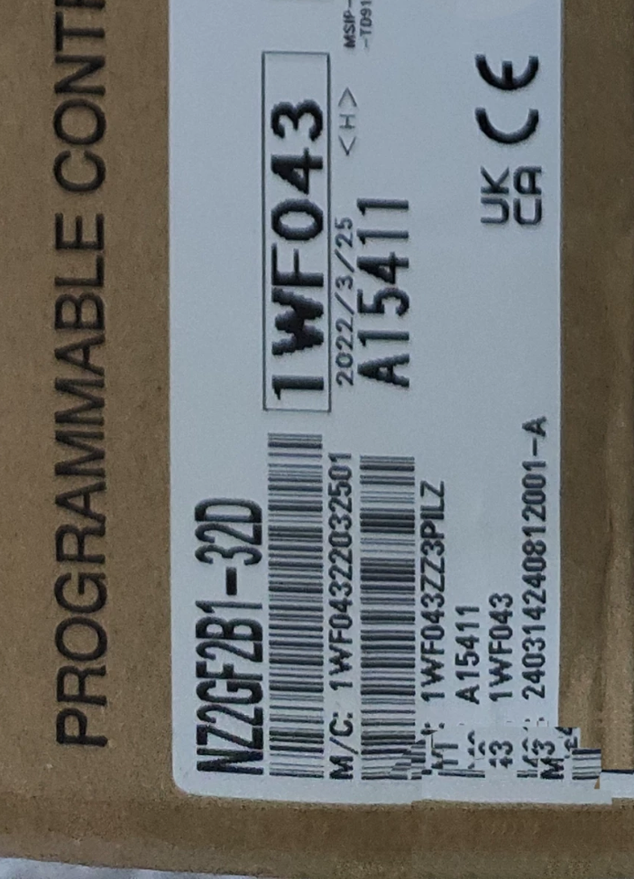

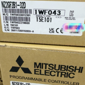
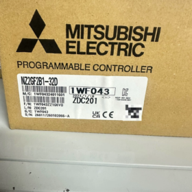
Detalhamento do código do modelo
| Código | Definição |
| Nova Zelândia | Série de E/S remota de campo CC-Link IE |
| 2G | 2Fieldbus CC-Link IE de segunda geração Gigabit Fieldbus |
| F | Unidade remota de E/S digital |
| B1 | Tipo de bloco terminal padrão (Não impermeável / Não de alta velocidade) |
| 32 | Total 32 Pontos de E/S |
| D | Módulo de entrada digital CC |
Posicionamento do produto: Gigabit Ethernet CC-Link IE Field inteligente módulo de estação remota com entradas digitais DC24V de 32 pontos, compatível com estações mestre PLC da série Q/L/R/FX5U.
- Especificações elétricas principais
2.1 Especificações de entrada
Pontos: 32-ponto de entrada digital DC24V, todos 32 pontos compartilham um terminal COM comum, compatível com fiação de dissipador e fonte (suporta modos comuns positivos/negativos)
Tensão nominal: CC24V (faixa permitida: 20.4~28,8 V, ondulação ≤5%)
Corrente de entrada de ponto único: Típico 6mA @ 24V, resistência de entrada 3,8kΩ
Limite LIGADO: ≥15V / ≥4mA; Limite DESLIGADO: ≤5V / ≤1,5mA
Tempo de resposta (8 engrenagens selecionáveis por software, padrão 10ms): 0/0.2/1/1.5/5/10/20/70EM
Isolamento: Isolamento do optoacoplador; Tensão suportável AC510V para 1 minuto, resistência de isolamento ≥10MΩ (CC500V)
Simultâneo LIGADO: 100% ON simultâneo de ponto completo sem limitação de queda de tensão
- Potência do Módulo & Comunicação
Fonte de alimentação da unidade: CC24V, consumo total de energia ≤120mA (todos os pontos LIGADOS)
Tipo de ônibus: CC-Link IE Field 1000BASE-T Gigabit Ethernet
Portas de rede: RJ45 duplo (ENTRADA/SAÍDA, topologia em cadeia). Cabos diretos STP com blindagem dupla Cat5e ou superior são obrigatórios
Tipo de estação: Estação de dispositivo inteligente, ocupa 1 estação lógica
Registros de Comunicação: RX/RY = 32 pontos; RWr/RWw = 20 palavras cada
Classe de Proteção: IP2X (apenas proteção de terminal interno; instalação descoberta ao ar livre proibida)
- Dimensões Mecânicas & Peso
Tamanho do contorno: A50 × L200 × D68 mm
Peso: 0.38 kg
Montagem: Montagem em trilho DIN padrão de 35 mm; unidades de extensão não podem ser conectadas
Terminais: 34-posicionar terminais de E/S de parafuso M3.5; potência da mola & Terminais FG
- Especificações Ambientais & Certificações
Temperatura operacional: 0~55°C; Temperatura de armazenamento: -20~75°C
Umidade: 5~95% UR (sem condensação)
Resistência à vibração: Em conformidade com os padrões industriais JIS B3502, IEC61131-2
Certificações: CE, UL/cUL, RoHS, Sociedades de Classificação Marinha (DNV/ABS/LR/KC)
- Instruções de fiação
- Circuito de Comunicação
Estação mestre PLC RJ45 → Módulo P1(EM); Conexão em cadeia de vários módulos: P2(FORA) conecta ao P1 do próximo módulo. Não é necessário resistor de terminação nas extremidades da linha.
- Fonte de alimentação do módulo
Terminais de mola de fio para DC24V+, 0Aterramento V e FG (todas as blindagens dos cabos devem ser conectadas ao FG uniformemente).
- Circuito de entrada (COM comum único)
Fiação da pia (Sensores NPN): Terminal COM conectado a 0V, 24Sinal do sensor V+ conectado aos terminais de entrada
Fiação de Fonte (Sensores PNP): Terminal COM conectado a 24V+, 0Sinal do sensor V conectado aos terminais de entrada
Todos 32 pontos compartilham um COM comum, permitindo fiação simples para coleta em massa de chaves fim de curso e sensores de proximidade.
- Principais pontos de configuração de software (GX Works3)
- Módulos de estação mestre suportados: QJ71GF11-T2 / LJ71GF11-T2 / FX5-CCLIEF
- Adicione estações remotas nos parâmetros de rede, selecione o modelo NZ2GF2B1-32D
- Tempo de resposta do filtro configurável de forma independente por canal para suprimir a vibração do sinal de campo
- Quebra de fio embutida / função de diagnóstico de circuito; PLC pode ler códigos de falha do módulo
- Cenários típicos de aplicação
Coleta centralizada de sinais de sensores fotoelétricos de massa, interruptores de proximidade e interruptores de limite em linhas de montagem
Aquisição remota de sinais em múltiplas estações para linhas de soldagem automotiva, sistemas de classificação de embalagens e logística
E/S distribuída para máquinas de grande porte para reduzir o comprimento da fiação do gabinete e reduzir os custos com cabos
Linhas de produção interconectadas com várias máquinas; Gigabit CC-Link IE garante transmissão de sinal em alta velocidade em tempo real
- Comparação de séries & Referência de seleção
| Modelo | Pontos | Tipo | Terminal Comum | Cenário de aplicação |
| NZ2GF2B1-32D | 32DE | Entrada digital CC | 32 pontos / 1 COM | Coleção de interruptores de entrada pura em massa |
| NZ2GF2B1-32T | 32Saída do transistor DO | Saída digital | 16 pontos / 1 COM | Válvula solenóide & luz indicadora de condução |
| NZ2GF2B1-32DTE | 16D+16C | E/S mista | Entrada:32pontos/1COM; Saída:16pontos/1COM | Coleta de sinais mistos para pequenas estações de trabalho |
- Precauções & Armadilhas Comuns
- Somente cabos STP com blindagem dupla devem ser usados para comunicação; conecte ambas as extremidades da blindagem do cabo aos terminais do PLC e do módulo FG para eliminar interferência de comunicação.
- Fontes de alimentação DC24V independentes separadas são recomendadas para sensores externos e alimentação do módulo para evitar falso disparo de sinal causado por queda de tensão.
- 0O tempo de resposta de ms só é aplicável para sinais de pulso de alta velocidade; 5Filtro de ~10ms é recomendado para switches comuns para evitar trepidação.
- Versões europeias foram anunciadas EOL (Fim da vida); oferta interna permanece estável. Novos projetos podem selecionar a série NZ2GF3 de nova geração como alternativa.
Mitsubishi Manual de instalação NZ2GF2B1-32D (Versão completa em inglês)
Manual Padrão Aplicável: Manual do usuário do módulo de E/S remota de rede CC-Link IE Field (Documento Não. SH-081113 Versão Chinesa)
Índice
- Avisos de segurança (Avisos / Cuidados)
- Especificações do produto & Estrutura Externa
- Requisitos ambientais de instalação
- Instalação em trilho DIN & Procedimentos de remoção
- Configuração do interruptor DIP do número da estação
- Especificações completas de fiação de terminal (Poder, FG, 32Entradas DI, Cabos CC-Link IE)
- Especificações obrigatórias de fiação para redução de ruído
- Lista de verificação de inspeção pré-ligação
- Diretrizes de configuração de rede de software PLC
- Falhas comuns pós-instalação & Contramedidas
1 Avisos de segurança (Conformidade Obrigatória)
AVISO (Risco de lesão fatal ou grave)
- Corte todas as fontes de alimentação DC24V do sistema antes de qualquer instalação, fiação, operações de desmontagem e montagem. Conexão/desconexão a quente de cabos Ethernet, blocos terminais e módulos é estritamente proibido.
- O terminal de aterramento FG deve ser aterrado de forma independente com resistência de aterramento ≤100Ω para evitar choque elétrico, interferência de comunicação e desgaste do módulo.
- Nunca conecte cabos AC220V ou de alta tensão a E/S ou terminais de alimentação; isso queimará diretamente o módulo e causará riscos de incêndio.
- Fusíveis externos devem ser instalados dentro do gabinete de controle para proteger o circuito de alimentação DC24V do módulo.
- Somente eletricistas certificados estão autorizados a realizar trabalhos de instalação e comissionamento.
CUIDADO (Risco de danos ao equipamento & Mau funcionamento)
- Aperte os parafusos do terminal estritamente de acordo com o torque padrão; torque insuficiente causa superaquecimento e curtos-circuitos, enquanto o torque excessivo desgasta as roscas e danifica as bases dos terminais.
- Os cabos de comunicação devem adotar cabos diretos STP com blindagem dupla Cat5e ou superior. Cabos UTP não blindados são proibidos.
- Separe os cabos de alimentação dos cabos de comunicação/E/S durante o roteamento com uma folga mínima de 100 mm para evitar interferência eletromagnética.
- Instalação direta em ambientes com muita poeira, condensação ou gás corrosivo é proibido; gabinetes de controle selados são necessários para proteção.
- Evitar água, detritos de metal e restos de fios de cobre entrem no interior do módulo, o que levará à queima de curto-circuito.
2 Aparência do produto & Especificações básicas
2.1 Definição de modelo
NZ2GF2B1-32D: Módulo de estação remota inteligente Gigabit CC-Link IE Field com entradas digitais DC24V de 32 pontos
2.2 Dimensões do contorno
Largura 200 mm × Altura 50 mm × Profundidade 68 mm, peso 0,38kg, montagem em trilho DIN padrão de 35 mm
- Zonas do painel frontal
- Seção Superior: Portas RJ45 duplas P1(EM), P2(FORA) (para fiação em cadeia)
- Seção intermediária: 8-posição do interruptor do número da estação DIP, indicadores LED de operação
- Inferior Esquerdo: Terminais de alimentação do módulo tipo mola (+24V, 0V, FG)
- Inferior Direito: 34-posicione os terminais de entrada de E/S do parafuso M3 (32DE + 2 terminais COM paralelos)
2.4 Definições de indicadores LED
CORRER: Verde constante = operação normal; Piscando = falha de comunicação; Desligado = Sem fonte de alimentação
LINK: Indicador de link de porta; Estável = Cabo conectado; Piscando = transmissão/recepção de dados
ERRAR: Vermelho constante = número de estação duplicado / Quebra de cabo / Falha no módulo / Curto-circuito no circuito de entrada
3 Requisitos ambientais de instalação obrigatória
3.1 Temperatura & Umidade
Temperatura operacional: 0℃ ~ +55℃ (garantir uma boa ventilação dentro do gabinete; não monte perto de inversores ou contatores geradores de calor)
Armazenar & Temperatura de transporte: -20℃~+75℃
Umidade: 5%~95% UR, sem condensação em todos os momentos
- Restrições de local de instalação
- Somente montagem vertical em trilho DIN é permitida (frente do módulo voltada para frente); de cabeça para baixo, montagem plana lateral ou horizontal é proibida.
- Mantenha uma distância mínima de 300 mm de fontes eletromagnéticas fortes, incluindo inversores, servoacionamentos, contatores e motores de alta potência.
- Não instale sob luz solar direta, água pingando, contaminação por óleo ou condições de poeira pesada.
- Reserve espaços de ventilação ≥50 mm acima e abaixo dos módulos dentro do gabinete; não são necessárias lacunas para instalação de vários módulos lado a lado.
4 Instalação em trilho DIN & Etapas de remoção
4.1 Procedimento de instalação
- Confirme se o trilho é um trilho DIN de aço padrão de 35 mm com montagem fixa firme sem tremer.
- Abra as travas superior e inferior na parte traseira do módulo para baixo.
- Prenda a trava superior na borda superior do trilho, prenda o módulo ao trilho e empurre para cima com força.
- Encaixe a trava inferior para cima para travar totalmente o módulo sem soltá-lo.
- Instale batentes de trilho em ambas as extremidades do trilho para evitar o deslizamento horizontal dos módulos.
4.2 Procedimento de remoção
- Desligue todas as fontes de alimentação DC24V e aguarde 3 minutos para descarga do capacitor.
- Pressione a trava inferior para forçá-la para baixo, levante a parte inferior do módulo para cima para soltá-la do trilho.
- Remova o módulo; não puxe cabos com força bruta.
5 Configuração do número da estação DIP (Ajuste obrigatório antes da instalação)
8-posicione a chave DIP no painel frontal do módulo para configuração do número da estação binária (estações inteligentes 1~120)
- DIP ON = Binário 1, DESLIGADO = Binário 0; a 1ª posição é o bit menos significativo
- Exemplo: Estação No.1 → DIP 1 SOBRE, outros DESLIGADOS; Estação No.5 → DIP 1 & 3 SOBRE
- Regras Críticas:
Todas as estações remotas em uma rede CC-Link IE devem ter números de estação exclusivos; números duplicados acionam falhas de luz vermelha ERR
Desligue e ligue o módulo após configurar para ativar o novo número de estação
Padrão de fábrica: Todos DIP OFF (Estação nº.0, comunicação desabilitada; modificação obrigatória)
6 Especificações completas de fiação de terminal (Conteúdo principal de instalação)
6.1 Terminais de energia de mola (3-posição lado esquerdo)
| Terminal nº. | Sinal | Requisito de fiação | Torque |
| 1 | +24Em DC | Pólo positivo da potência operacional do módulo; fonte de alimentação DC24V independente | 0.5~0,8N·m |
| 2 | 0V | Pólo negativo de energia, terra comum com alimentação do sensor 0V | 0.5~0,8N·m |
| 3 | FG | Terra do escudo, conectar à barra de aterramento do gabinete; resistência de aterramento ≤100Ω | 0.5~0,8N·m |
Consumo de energia: ≤120mA com todos os pontos LIGADOS; capacidade de energia recomendada ≥300mA por módulo único
Proibido: Compartilhe fios finos para sensor externo 24V e alimentação do módulo para evitar falsos disparos de entrada causados por queda de tensão
6.2 Terminais de entrada de E/S (34-posicione os parafusos M3, Lado direito)
Disposição dos Terminais (32 pontos de entrada, dois terminais COM paralelos):
1:X0 2:X1 3:X2 4:X3 5:X4 6:X5 7:X6 8:X7
9:X8 10:X9 11:XA 12:XB 13:XC 14:XD 15:CARRO 16:XF
17:COM 18:COM (dois terminais comuns paralelos, compartilhado para todos 32 pontos)
19:X10~ 32:X1F (restante 16 pontos de entrada)
Dois modos de fiação do sensor
- Fiação da pia (Proximidade NPN principal / sensores fotoelétricos)
Terminal COM conectado a 0V; 24Sinal de saída do sensor V+ conectado aos terminais X
- Fiação de Fonte (Sensores PNP)
Terminal COM conectado a +24V; 0Sinal de saída do sensor V conectado aos terminais X
Classificação de entrada: CC24V, LIGADO ≥15V, DESLIGADO ≤5V, corrente de ponto único 6mA
Torque de parafuso terminal padrão: 0.8~1,2N·m
6.3 Fiação do cabo de campo CC-Link IE (Portas RJ45 P1/P2)
- Topologia: Conexão em cadeia
Estação mestre PLC RJ45 → Módulo remoto P1(EM); Módulo P2(FORA) → P1 do próximo módulo
- Padrões obrigatórios de cabos
Cabo: Cabo direto STP com blindagem dupla Cat5e/Cat6; blindagens de cabos crimpadas em caixas metálicas RJ45 em ambas as extremidades
Comprimento máximo de segmento único: 100eu (não deve ser excedido)
Cabos cruzados, cabos não blindados e cabos de baixa qualidade são proibidos
- Tratamento de Escudo: Conecte as extremidades da blindagem do cabo ao mestre PLC FG e ao módulo FG respectivamente; aterramento de extremidade única ou dupla é aceitável, escudo flutuante é proibido.
7 Especificações de fiação para redução de ruído (Evite interrupções na comunicação & Entrada de disparo falso)
- Cabos de alimentação separados (AC220V, fios do motor) de cabos de comunicação/E/S em bandejas de cabos separadas com espaço mínimo de 100 mm; instale divisórias de blindagem metálica se a separação for impossível.
- Todos os cabos roteados dentro de eletrocalhas metálicas com aterramento confiável.
- Aterramento de extremidade única para fios de sinal de E/S; o aterramento de extremidade dupla multiponto é proibido para evitar interferência de corrente circulante.
- Evite passar os cabos próximos ao longo dos lados de saída do inversor ou do contator.
- Enrole o excesso de cabos em pequenos laços; roteamento circular em grandes áreas é proibido (risco de interferência indutiva).
- Comprimento de decapagem do fio controlado em 5~6mm para evitar exposição do fio de cobre e riscos de curto-circuito.
8 Lista de verificação de inspeção completa do sistema antes da inicialização (Obrigatório após a instalação)
- Terminais de energia: Sem curto-circuitos, sem fiação de polaridade reversa, FG aterrado de forma confiável
- Terminais de E/S: Nenhuma sobreposição de fio de cobre entre terminais adjacentes, Fiação COM correta
- Cabos Ethernet: Cabos blindados STP totalmente inseridos, sem links soltos, sem topologia de loop
- Chaves DIP de estação: Conjunto exclusivo de número de estação diferente de zero, sem números de estação duplicados na rede
- Instalação Mecânica: Travas do módulo totalmente travadas, rolhas de trilho fixas, sem tensão nos cabos
- Ambiente: Sem acúmulo de água, detritos de metal ou acúmulo de poeira dentro do gabinete
9 Configuração de software CLP (Configurações de correspondência do GX Works3)
9.1 Módulos de estação mestre compatíveis
Série Q: QJ71GF11-T2; Série L: LJ71GF11-T2; Série FX5U: FX5-CCLIEF
9.2 Etapas de configuração dos parâmetros de rede
- Criar novo projeto, navegar para [Parâmetros de rede] → Campo CC-Link IE
- Adicionar estação remota inteligente, selecione o modelo NZ2GF2B1-32D, configuração do interruptor DIP correspondente ao número da estação de entrada
- Ocupação de Estação Lógica: 1 estação; RX/RY alocado para 32 pontos de entrada, 20 RWR & 20 Registros RWw
- Tempo de resposta do filtro de entrada (8 engrenagens de software): 0/0.2/1/1.5/5/10/20/70EM
Interruptores comuns: 5~10ms para anti-vibração; sinais de pulso de alta velocidade: 0EM
- Escrever parâmetros no PLC, reinicie o PLC e os módulos remotos; luz RUN constante indica comunicação normal
10 Falhas comuns pós-instalação & Contramedidas
| Fenômeno de falha | Causa raiz (Relacionado à instalação) | Ação Corretiva |
| Luz de FUNCIONAMENTO apagada | Alimentação do módulo 24V desconectada / fiação de polaridade reversa | Verifique novamente a fiação do terminal de alimentação |
| Luz ERR vermelha constante | Número da estação duplicado / DIP definido como 0 / cabo Ethernet quebrado | Reatribuir número de estação exclusivo, inspecionar o cabo STP |
| Nenhum sinal de entrada com sensor funcional | Fiação COM reversa / parafusos terminais soltos | Aperte os terminais de E/S, verifique a fiação do coletor/fonte |
| Abandono frequente de comunicação | Cabo não blindado, escudo não aterrado, roteado junto com cabos de alimentação | Substitua pelo cabo blindado STP, fiação separada, conectar o terra FG |
| Acionamento aleatório de entrada falsa | Fonte de alimentação compartilhada para sensores e módulo, nenhum filtro ativado | Implemente alimentação de sensor DC24V independente, aumentar o tempo de filtro de software |
11 Instalação & Operações Proibidas de Manutenção (Restrições rígidas)
- A conexão/desconexão a quente de cabos Ethernet RJ45 e blocos terminais de E/S é estritamente proibida
- A tensão CA nunca deve ser conectada a nenhum terminal do módulo
- Não desconecte o aterramento do módulo FG nem deixe as blindagens dos cabos flutuando
- Não aperte demais os parafusos do terminal para evitar desgaste da rosca e danos à base
- Não instale módulos em ambientes externos desprotegidos ou em condições de condensação de alta umidade
- Cabos UTP comuns não podem ser usados para fiação de comunicação CC-Link IE





NH42-63-318x560.png "Chaves de transferência automática tipo PC CHINT (ATS)NH42-63/4SZ")



