 Contator,disjuntor,sensor,Codificador,CLP,Conversor

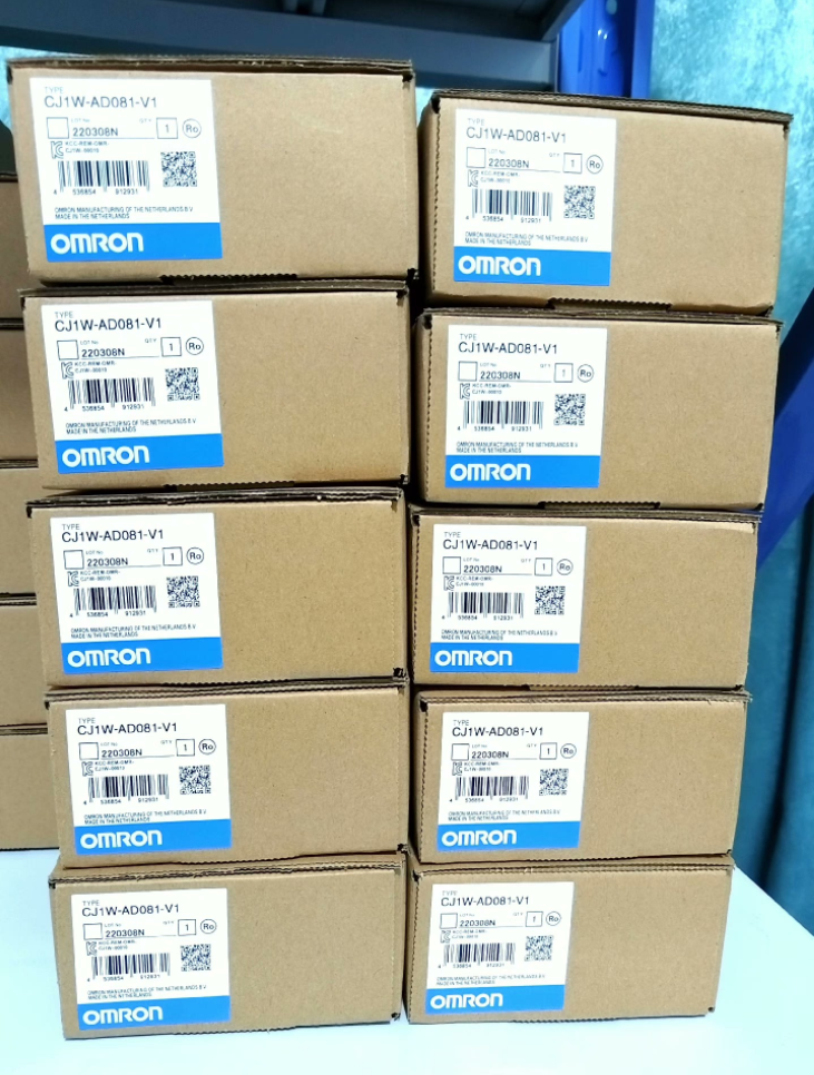

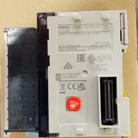
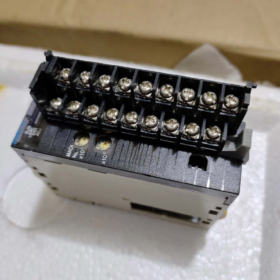
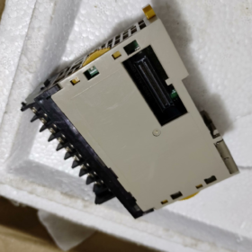
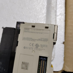
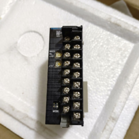
CJ1W-AD081-V1
- CJ1W: Base de série de módulo de E/S especial para PLCs da série CJ1
- ANÚNCIO: Entrada Analógica
- 08: 8 canais de entrada analógica
- 1: Revisão de hardware padrão
- V1: Versão funcional atualizada (suporta detecção de quebra de fio, comutação de resolução dupla, e filtro de suavização digital)
Modelo Derivativo: CJ1W-AD081-V1-SL (tipo de terminal sem parafuso de mola)
- Especificações básicas de hardware
Parâmetros Básicos
| Item | Especificação |
| Número de canais | 8 entradas analógicas independentes (CH1~CH8) |
| CPUs PLC compatíveis | Linha completa de CJ1M / CJ1H / CJ2M / CPU CJ2H |
| Interface de ônibus | Barramento de E/S dedicado do backplane CJ; nenhuma fonte de alimentação externa necessária |
| Consumo de energia do backplane | CC 5V ≤ 420mA |
| Esquema de Isolamento | Isolamento do optoacoplador entre o circuito do módulo interno e o barramento PLC; sem isolamento entre canais individuais |
| Dimensões Gerais | L31mm × A90mm × D65mm |
| Peso | ≤ 140g |
| Ambiente Operacional | 0~55°C, 10%~90% RH sem condensação |
| Especificações do terminal | Modelo padrão: Terminais de parafuso M3; Modelo SL: terminais de desconexão rápida de mola, 18-bloco terminal destacável de pino |
Faixas de sinal de entrada (Chave DIP de hardware selecionável por canal)
Entrada de Tensão (Interruptor DIP = DESLIGADO)
-10~+10V, 0~10V, 0~5V, 1~5V
Impedância de entrada: ≥1MΩ, Tensão máxima suportável: ±15V
Entrada atual (Interruptor DIP = LIGADO, resistor de amostragem de 250Ω integrado)
4~20mA, 0~20mA
Impedância de entrada: 250Oh, Corrente máxima suportável: ±30mA
Precisão de conversão & Resolução
- Dois graus de resolução selecionáveis por software
4000-contar (12-pedaço): Modo econômico com velocidade de conversão rápida
8000-contar (13-pedaço): Modo de alta precisão para medição precisa de vazão/pressão
- Precisão em escala total (Temperatura ambiente: 25°C)
Entrada de Tensão: ±0,2% FS
Entrada atual: ±0,4% FS
- Precisão da faixa de temperatura total (0~55°C)
Sinal de Tensão: ±0,4% FS
Sinal atual: ±0,6% FS
- Velocidade de conversão: 1ms por canal; verificação completa de 8 canais leva 8ms; modo de alta velocidade: 250μs por canal
- Funções principais integradas
- Detecção de ruptura de fio (Dedicado para circuitos de 4~20mA)
Quando um loop de corrente está aberto, o sinalizador de quebra de fio do canal correspondente é ativado para alarme baseado em programa.
- Filtro de suavização digital
Cálculo do valor médio para suprimir a instabilidade do sensor e a interferência eletromagnética no local.
- Pico / Vale do Vale
Captura e bloqueia os valores analógicos máximos e mínimos dentro de um ciclo, adequado para pressão de impacto e aquisição instantânea de fluxo.
- Desvio / Calibração de ganho
Os registros de calibração integrados permitem a correção no local do desvio de zero do sensor.
- Dimensionamento de intervalo personalizado
Os limites superior e inferior de ±32.000 podem ser configurados para mapear diretamente sinais de 4–20mA para valores de engenharia como 0~1000 ou 0~5000.
- Definição de fiação terminal (18-Bloco terminal de pinos)
Cada canal ocupa dois terminais: V+ (Sinal Positivo), COM (Negativo Comum)
CH1: Pino1(V+), Pino2(COM)
CH2: Pino3(V+), Pino 4(COM)
CH3: Pino 5(V+), Pino 6(COM)
CH4: Pino 7(V+), Pino 8(COM)
CH5: Pino 9(V+), Pino 10(COM)
CH6: Pino11(V+), Pino 12(COM)
CH7: Pino13(V+), Pino 14(COM)
CH8: Pino 15(V+), pino16(COM)
Pino 17, Pino 18: Terminais de aterramento blindados (Conecte todos os cabos de blindagem do sensor aqui para desempenho anti-interferência)
Diretrizes de fiação
- Sinais de tensão: Conecte apenas V+ e COM; coloque a chave DIP em OFF
- 2-fio transmissores 4 ~ 20mA: Conecte V+ ao terminal positivo do transmissor, Terminal negativo COM para 24V; coloque a chave DIP em ON
- Recomenda-se comumizar os terminais COM de vários sensores. Conecte as camadas de blindagem aos pinos 17/18 do módulo em apenas uma extremidade; o aterramento duplo é proibido.
- Alocação de memória PLC (Unidade de E/S Especial)
- Área de relé de entrada (10 Palavras): Armazena valores brutos de conversão A/D para 8 canais
CH1: Palavra do canal 0; CH2: Palavra do canal 1 …CH8: Palavra do canal 7
- Área de relé de saída (10 Palavras): Registros de configuração de função
Inclui mudança de resolução, contagem de amostragem de filtro, detecção de quebra de fio habilitada, parâmetros de limite de escala superior/inferior
- Software de configuração: Programador CX + Integrador CX. Os endereços dos canais são atribuídos automaticamente após registrar o módulo na tabela de E/S.
- Cenários típicos de aplicação industrial
- Controle de Fluidos: Aquisição de transmissores de pressão 4–20mA, nível e fluxo de líquido
- Sistemas de controle de temperatura: 0~10V / 1Módulos transmissores de temperatura ~5V
- Feedback Analógico para Inversores & Servo Drives: Coleta de sinais de feedback de velocidade e torque de 0 ~ 10 V
- Aquisição centralizada de sinais analógicos multiponto para tratamento de água, máquinas químicas e de embalagem
- Comparação da Mesma Série & Soluções de substituição
Comparação de módulos de entrada analógica na mesma série
| Modelo | Contagem de canais | Principais recursos |
| CJ1W-AD041-V1 | 4 canais | Solução de baixo custo para aquisição pontual em pequena escala |
| CJ1W-AD081-V1 | 8 canais | Modelo padrão de uso geral com maior estoque de mercado |
| CJ1W-AD161 | 16 canais | Aquisição de alta densidade; sem funções aprimoradas V1 |
Atualizar & Substituições Compatíveis
- Substituição direta na mesma plataforma: CJ1W-AD081-V1-SL (terminais de mola, parâmetros de hardware idênticos; nenhuma modificação do programa necessária)
- Compatibilidade da Série CJ2: Montagem direta em CPUs CJ2M/CJ2H com configuração de E/S inalterada
- Substituição para série CS legada: CS1W-AD081-V1 (Backplanes são incompatíveis; A substituição do rack da CPU é obrigatória)
- Alternativa da série NX de nova geração (Recomendado para novos projetos): NX-AD4208 (8-entrada analógica do canal, Barramento EtherCAT)
- Matriz de solução de problemas de falhas comuns
| Fenômeno de falha | Causas Raiz | Etapas de resolução |
| Todos os canais mostram valor zero fixo | 1. Módulo não cadastrado no CX-Integrator; 2. Mau contato com o backplane; 3. Fonte de alimentação de backplane de 5 V insuficiente | 1. Reconstrua e baixe a tabela de E/S; 2. Remova e recoloque o módulo com firmeza; 3. Reduza o número de módulos instalados no backplane |
| Valor de canal único inalterado / preso em escala real | 1. Configuração incorreta da chave DIP para modo tensão/corrente; 2. Circuito aberto/curto-circuito na fiação de sinal; 3. Perda da fonte de alimentação de 24 V para o transmissor | 1. Verifique a configuração do interruptor DIP do canal; 2. Teste a continuidade do circuito com um multímetro; 3. Verifique a fonte de alimentação dos sensores |
| Alarmes freqüentes de quebra de fio em canais de 4–20 mA | 1. Queda excessiva de tensão ao longo dos cabos; 2. Capacidade de carga insuficiente dos transmissores; 3. Conexões terminais soltas | 1. Use cabos de sinal mais grossos; 2. Encurtar o comprimento do cabo; 3. Aperte os parafusos do terminal |
| Desvio e flutuação graves do sinal | 1. Aterramento da blindagem não conectado; 2. Filtro de suavização desativado; 3. Cabos analógicos colocados em paralelo com cabos de potência dentro da mesma calha | 1. Conecte os fios blindados aos terminais de aterramento do módulo; 2. Habilitar filtro médio no software; 3. Fiação separada de sinal baixo e fiação de alta potência |
| Erro de conversão excessivo | 1. A temperatura ambiente excede 55°C; 2. Deriva zero de longo prazo; 3. Sinais externos fora da faixa nominal | 1. Melhorar o resfriamento do gabinete de controle; 2. Execute a calibração de deslocamento/ganho; 3. Confirme a correspondência da faixa de medição do transmissor |
- Restrições de uso (Operações estritamente proibidas)
- Não configure as chaves DIP dos canais de entrada de tensão para o modo de corrente; isso queimará o resistor de amostragem interno do módulo
- Nunca aplique sinais de entrada superiores a ±15V (modo de tensão) ou ±30mA (modo atual); Chips A/D podem sofrer quebra permanente
- Evite o roteamento paralelo de cabos de sinal analógico com cabos de potência para inversores e contatores na mesma calha de cabos; interferência eletromagnética severa causará distorção de dados
- O aterramento duplo das camadas de blindagem do transmissor é proibido, já que a corrente circulante introduzirá interferência na frequência de potência
- Desligue todo o sistema PLC antes de conectar/desconectar módulos; a troca a quente danificará as interfaces de barramento do backplane
Especificações oficiais de precisão de CJ1W-AD081-V1 (Por Padrões Manuais OMRON)
- Precisão nominal à temperatura ambiente (23±2°C / 25°C, Erro em escala total)
- Entrada de Tensão (0~5V / 0~10V / -10~+10V / 1~5V)
Precisão geral: ±0,2% FS
- Entrada atual (4~20mA / 0~20mA)
Precisão geral: ±0,4% FS
> Observação: FS = escala completa, referindo-se ao erro relativo em toda a faixa do sinal, incluindo ponto zero integrado, erros de ganho e linearidade.
- Precisão em toda a faixa de temperatura (0~55°C Temperatura operacional)
Sinais de Tensão: ±0,4% FS
Sinais Atuais: ±0,6% FS
- Resolução (Distinção entre “Precisão” e “Resolução”)
A resolução refere-se à alteração mínima detectável do sinal e não é equivalente à precisão:
- Modo de baixa velocidade (1ms por canal): 1/4000 (12-pedaço)
- Modo de alta velocidade (250μs por canal): 1/8000 (13-pedaço)
Exemplos de cálculo de erros
Cálculo baseado em 4~20mA (extensão total = 16mA) com precisão de corrente ±0,4%FS:
Erro Absoluto Máximo = 16mA × 0.4% = ±0,064mA
Cálculo baseado em tensão de 0~10V com precisão de ±0,2%FS:
Erro Absoluto Máximo = 10V × 0.2% = ±0,02 V
- Observações Suplementares
- A calibração padrão de fábrica é otimizada para sinais de tensão. Para aplicações de loop de corrente de 4–20 mA, realizar calibração de deslocamento/ganho via software para reduzir ainda mais erros de medição de corrente.
- Não existe isolamento galvânico entre os canais. Erros de medição adicionais podem ser introduzidos pela fiação de aterramento comum do multissensor, cabos longos ou interferência eletromagnética pesada; tais erros não estão incluídos na classificação de precisão nominal do módulo.
- A precisão especificada exclui fontes de erro externas, como erro intrínseco do sensor, queda de tensão do cabo e interferência de aterramento.
Cenários completos de aplicação de CJ1W-AD081-V1 (Classificado por Indústria, Equipamentos e Sinais Coletados)
Este é um módulo de aquisição analógica de 8 canais de uso geral compatível com 4 ~ 20mA / 0~10V / 1Sinais de ~5V, equipado com detecção de quebra de fio, funções de filtragem digital e retenção de pico. Ele suporta CPUs CJ1H/CJ1M/CJ2M/CJ2H e é ideal para coleta contínua de quantidades físicas multiponto, controle de processos em circuito fechado e monitoramento de condições de equipamentos. Sem isolamento entre canais, tornando-o adequado para redes de sensores que compartilham um terreno comum no mesmo local.
- Químico / Tratamento de Água / Proteção Ambiental (Campo de aplicação mais comum)
Sinais coletados
Principalmente transmissores de 2 fios 4 ~ 20mA: nível de líquido, pressão do gasoduto, taxa de fluxo, PH/ORP, oxigênio dissolvido, turbidez, concentração de reagente químico, temperatura do reator
Equipamento & Sistemas
- Equipamento completo para tratamento de águas residuais: Controle de dosagem em circuito fechado baseado no nível de líquido do tanque bioquímico, pressão de aeração, taxas de fluxo influente e efluente, e nível de líquido do tanque de produtos químicos
- Água pura / equipamento de osmose reversa: Coleta do fluxo de água do produto, sinais do transmissor de pressão diferencial e condutividade pré/pós-membrana
- Reatores químicos / misturando chaleiras: Controle interligado de temperatura e pressão com base na temperatura da chaleira, pressão interna e fluxo de alimentação de matéria-prima
- Tratamento de gases de escape / dessulfurização & desnitrificação: Monitoramento da temperatura dos gases de combustão, pressão diferencial, fluxo de reagente e concentração de neutralização ácido-base
Vantagens do Módulo
4Detecção de ruptura de fio de ~20mA: Alarme automático para cabos quebrados ou perda de energia dos transmissores
A filtragem digital elimina a interferência na frequência de energia de bombas de água e ventiladores
8 canais permitem a aquisição simultânea de vários pontos de medição de tanques e tubulações para reduzir a quantidade total de módulos
- Comida & Bebida / Farmacêutico / Linhas de produção de refeições prontas
Sinais coletados
Transmissores de temperatura (PT100 convertido para 4~20mA), nível de líquido do tanque, fluxo de xarope/material, pressão de enchimento, grau de vácuo
Equipamento
- Esterilizando chaleiras, panelas: Controle de temperatura multiponto em circuito fechado com desligamento por intertravamento em caso de superaquecimento
- Sistemas de dosagem e mistura: Alimentação automática com base no nível do tanque de matéria-prima e na taxa de fluxo de entrega
- Equipamento de enchimento e moldagem por sopro: Coleta de pressão de enchimento e vácuo negativo para garantir precisão de enchimento
- Água purificada farmacêutica e tanques de mistura: Registro de dados compatível com nível de líquido, temperatura e pressão diferencial (Rastreabilidade de BPF)
Pontos fortes correspondentes
±0,2% FS de alta precisão em temperatura ambiente atende aos requisitos de medição do processo; pico de retenção captura flutuações de pressão instantâneas.
- Embalagem / Impressão / Borracha & Máquinas para Plásticos
Sinais coletados
Sinais de tensão predominantemente de 0 ~ 10 V: Feedback de velocidade do servo/inversor, sensores de tensão, pressão da cavidade do molde, pressão de extrusão fundida
Equipamento
- Vertical / máquinas de embalagem horizontais: Aquisição de tensão do rolo de filme e temperatura de selagem térmica para controle de malha fechada de tensão constante
- Moldagem por injeção / extrusoras: Temperatura do barril segmentado, pressão de fusão e pressão de óleo do sistema hidráulico
- Máquinas de impressão: Pressão de prensagem do rolo e sinais do transmissor de concentração de tinta
- Equipamento de moldagem por sopro e fabricação de sacos: Monitoramento da temperatura do molde e da pressão de fornecimento de ar
Vantagens correspondentes
A conversão de alta velocidade de 250 μs por canal captura tensão e pressão que variam rapidamente; aquisição multicanal centralizada de todos os sinais de feedback analógico de toda a máquina.
- AVAC, Automação Predial & Ar Condicionado Central
Sinais coletados
Temperatura & transmissores de umidade (4~20mA), pressão diferencial do duto de ar, fluxo de água fria/quente, pressão da água gelada, Concentração de CO₂
Sistemas
Ar condicionado central de fábrica, manipuladores de ar para salas limpas, temperatura constante & unidades de umidade para oficinas livres de poeira, ar fresco & sistemas de exaustão
Finalidade da aplicação
Ajuste automaticamente a velocidade do ventilador e a abertura da válvula de água gelada com base na temperatura interna, umidade e concentração de CO₂ para controle coordenado com economia de energia.
- Energia, Fotovoltaico, Bomba de água & Estações de fãs
Sinais coletados
Temperatura da bateria, intensidade de irradiância solar, pressão de saída da bomba, nível de líquido do tanque de água, temperatura do rolamento do motor
Cenários
- Armários de armazenamento de energia fotovoltaica: Medição de temperatura multiponto do ambiente e de baterias
- Salas de bombas de abastecimento de água com pressão constante: Controle de pressão constante de frequência variável e circuito fechado por meio de aquisição de pressão na tubulação
- Estações de compressores de ar: Monitoramento e aviso prévio da pressão do tanque de ar, temperatura de exaustão e temperatura do óleo lubrificante
- Equipamento auxiliar de caldeira: Fluxo de água de alimentação, pressão negativa do forno e temperatura de exaustão dos gases de combustão
- Máquinas-ferramentas, Linhas de produção automatizadas & Equipamento personalizado fora do padrão
Sinais coletados
Pressão do óleo hidráulico, pressão do cilindro, temperatura do fluido de corte, 0Sensores de deslocamento de ~10V, transmissores de vibração
Equipamento
Tornos CNC, linhas de montagem, equipamento de estampagem, dispositivos elétricos de teste automatizados
Funções principais
Aviso antecipado da condição do equipamento com desligamento automático por pressão de óleo excessivamente baixa ou alta temperatura; inspeção dimensional via coleta de sinal de deslocamento.
- Agricultura, Conservação da Água & Aquicultura
- Aquicultura: Intertravamento automático de aeração e troca de água com base no oxigênio dissolvido na água, temperatura da água e nível do líquido da lagoa
- Irrigação & conservação da água: Controle automático de irrigação por meio da coleta do fluxo da tubulação, sinais do transmissor de nível de líquido da piscina e umidade do solo
Cenários de aplicativos não recomendados (Seleção de modelo para evitar armadilhas)
- Demanda por forte isolamento entre vários canais: Somente o lado do barramento possui isolamento de optoacoplador sem isolamento entre canais. Para locais com aterramento separado de multisensores ou interferência severa, priorizar CJ1W-AD041-V2 (modelo isolado de canal).
- Armários de controle com alta tensão e campos eletromagnéticos intensos ou inversores densos: Isoladores de sinal externos devem ser instalados para evitar desvios graves de sinal.
- Menor que 4 pontos de medição analógicos: Selecione CJ1W-AD041-V1 para menor custo; escolha CJ1W-AD161 para aquisição de 16 pontos de alta densidade.
Valor do aplicativo correspondente às funções do módulo principal
- Detecção de ruptura de fio → Evita falhas de circuito para transmissores de 4–20 mA em tratamento de água e indústrias químicas
- Filtro Médio Digital → Anti-interferência para bombas de água no local, ventiladores e inversores
- Pico / Valley Hold → Registro da pressão de fusão por injeção e pressão de estampagem instantânea
- Desvio & Calibração de ganho → Corrige o desvio de zero do sensor de longo prazo para manter uma precisão de medição consistente
- 8-Compatibilidade de sinal misto de canal → Suporta fiação mista de transmissores de tensão e corrente em um único módulo para reduzir a contagem de módulos do gabinete





NH42-63-318x560.png "Chaves de transferência automática tipo PC CHINT (ATS)NH42-63/4SZ")



