 Contator,disjuntor,sensor,Codificador,CLP,Conversor

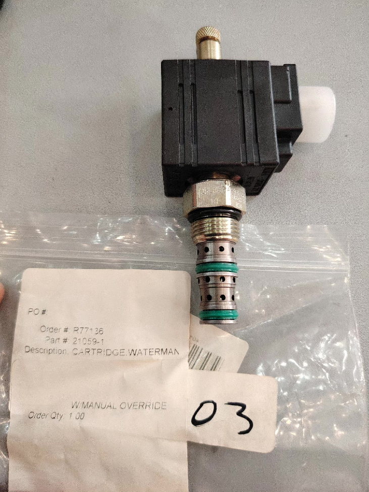

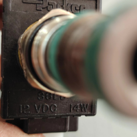
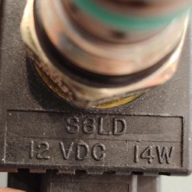
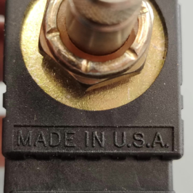
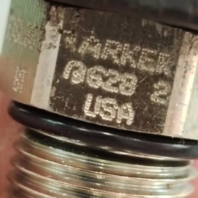
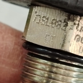
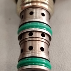
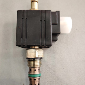
DSL083, 2-posição rosca tipo carretel de 3 vias válvula de cartucho com controle manual da opção T. Cavidade C08-3 (3/4-16 Rosca UNF-2A).
Explicação do código do modelo
DSL: Válvula solenóide de cartucho tipo carretel série de baixa pressão (250 bar); DSH significa versão de alta pressão (350 bar).
08: Tamanho 08, cavidade C08-3.
3: 3-função de caminho.
B: Função B (Desenergizado: porta2-1 conectada; Energizado: porta2-3 conectada, seletor tipo normalmente fechado).
T: T = controle manual push-twist. Nenhuma operação manual sem sufixo T.
Principais especificações técnicas
| Item | Especificação |
| Função | 2Carretel de 3 vias de posição, retorno por mola, com acionamento manual |
| Cavidade | C08‑3, rosca 3/4‑16 UNF‑2A |
| Pressão operacional máxima | 250 bar (3600 psi) |
| Fluxo Nominal | 15 L/min (4 GPM) |
| Vazamento | Aprox.. 180 cm³/min @250bar (vazamento intrínseco do carretel) |
| Torque de instalação | Cartucho: 31-37N·m (23-27 lb-ft); Porca de bobina: 7-10N·m |
| Tempo de resposta | Aprox.. 50 EM |
| Fluido | Óleo hidráulico de base mineral, viscosidade 6‑420cSt |
| Requisito de Filtragem | ISO 4406 18/16/13 |
| Faixa de temperatura | -37~+93°C; Vedações de nitrila de anel D padrão |
| Peso | Aprox.. 0.13 kg |
Lógica de Porta (Função B)
Desenergizado (posição da mola): 2 ↔1 conectado, porta3 bloqueada
Energizado (posição do solenóide): 2 ↔3 conectado, porta1 bloqueada
Usos típicos: Seleção de circuito, comutação piloto, partida-parada do motor, controle piloto de carga. Devido ao vazamento intrínseco do carretel, não é adequado para circuitos de retenção de vazamento zero.
Informações da bobina
A bobina é vendida separadamente. Use bobinas da série Parker Unicoil. Tensões comuns: 12 CCV, 24 CCV; Conector elétrico: Conector estilo automotivo DT04-2P.
Tensão operacional mínima: 85 % da tensão nominal.
Referências de substituição
- Substituição de queda de alta pressão Parker: DSH083BT (350 bar, mesma cavidade C08-3, direto intercambiável).
- Alternativa doméstica: SV08-33B-T (Cavidade C08-3, Função B, com acionamento manual). Verifique o fluxo, construção de pressão e controle manual.
Notas importantes
- O design tipo carretel cria vazamento inerente. Adicione válvula de retenção operada por piloto para aplicações de retenção de carga.
- A substituição manual T é do tipo push-twist apenas para comissionamento e emergência. NÃO opere continuamente na posição manual.
- Siga rigorosamente os valores de torque. O excesso de torque danifica a cavidade; subtorque aumenta o vazamento.
Casos de aplicação típicos para Parker DSL083BT (2-Válvula de cartucho de carretel de função B de 3 vias de posição)
Recapitulação da função da válvula: Desenergizado: 2-1 conectado, porta3 bloqueada; Energizado: 2-3 conectado, porta1 bloqueada; Substituição manual push-twist; Cavidade C08-3, 15 L/min, 250 bar; Vazamento intrínseco do carretel, não para retenção de vazamento zero.
A substituição manual T é adequada para comissionamento no local e operação de emergência em campo.
Caso1: Controle de elevação do cilindro de ação simples (Equipamento Móvel Mais Comum)
Equipamento: Plataformas de trabalho aéreo, implementos de elevação agrícolas, pequenos veículos de saneamento, racks de elevação
Arranjo do circuito: Porta2 = alimentação de pressão, Porta1 = tanque, Port3 = tampa do cilindro de simples ação.
Lógica de operação:
1) Desenergizado: 2-1 conectado, porta do cilindro 3 bloqueada. O cilindro mantém a posição, mas se desloca lentamente ao longo do tempo devido ao vazamento do carretel.
2) Energizado: 2-3 conectado, óleo sob pressão estende o cilindro (elevador). Após a desenergização, o peso da carga impulsiona a retração.
Função de substituição T: Para descida de emergência durante falhas de perda de energia, ativando o cancelamento manual.
⚠️Nota: Instale uma válvula de retenção operada por piloto para retenção de carga de longo prazo para compensar o vazamento do carretel.
Caso2: Comutação de Circuito Piloto (Coletores Hidráulicos Industriais)
Equipamento: Unidades hidráulicas compactas, unidades de energia de fixação, coletores de bancada de testes
Propósito: Alterne a pressão de alimentação do piloto para válvulas de alívio e válvulas de retenção operadas por piloto.
Circuito: Porta2 = fornecimento piloto, Porta1 = tanque, Port3 = porta de sinal piloto do componente downstream.
Desenergizado: A porta piloto se conecta ao tanque, pressão piloto ventilada.
Energizado: A porta piloto recebe pressão de controle para acionar componentes a jusante.
Vantagens: Design compacto para montagem em coletor. A substituição T permite o comissionamento do circuito sem energia elétrica.
Caso3: Descarga da bomba / Circuito de comutação de bypass
Equipamento: Máquinas auxiliares de moldagem por injeção, enfardadeiras, pequenas unidades de potência de prensa
Porta2 = saída da bomba, Porta1 = tanque, Porta3 = alimentação do sistema principal.
Desenergizado: Fluxo da bomba direcionado para o tanque para espera de baixa pressão, economia de energia.
Energizado: A bomba fornece pressão ao sistema principal para ciclos de trabalho.
Adequado para sistemas de serviço intermitente. O vazamento do carretel tem impacto insignificante. A substituição manual em T permite a descarga forçada para manutenção.
Caso4: Partida-Parada do Motor Hidráulico Unidirecional
Equipamento: Motores agitadores pequenos, acionamentos transportadores, atuadores rotativos
O motor gira apenas em uma direção; válvula controla on-off sem reversão de direção.
Port2 recebe pressão de alimentação. Energizado: pressão alimentada ao motor. Desenergizado: porta do motor bloqueada enquanto o fornecimento flui para o tanque.
Limitação: O motor gira lentamente quando parado devido a vazamento no carretel. Adicione válvula de freio para posicionamento preciso.
Caso 5: Seletor de Circuito Ramal
Equipamento: Ferramentas multiestações, bancadas de teste, selecione a alimentação para um dos dois atuadores
Porta2 = fornecimento comum. Energizado seleciona branch3; Desenergizado seleciona branch1 para realizar a seleção de circuito bidirecional.
Adequado para comutação de fluxo médio-baixo até 15L/min. A montagem do coletor reduz a tubulação externa.
Caso 6: Funções Auxiliares para Fora-de-estrada / Maquinaria agrícola
Equipamento: Acessórios para colheitadeira, equipamento paisagístico, perfurar cilindros auxiliares
Tolera altas vibrações e ampla faixa de temperatura (-37~+93℃). O conector de bobina estilo automotivo DT oferece resistência à vibração. A substituição T permite operação de emergência em campo durante perda de energia.
Não para circuitos principais de alto fluxo; destinado à fixação auxiliar, defletor, defletor e pequenos atuadores semelhantes.
Armadilhas de aplicação & Dicas de seleção para DSL083BT
- ❌Não é para retenção de carga com vazamento zero: Vazamento intrínseco ~180cm³/min @250bar. Válvula de retenção operada por piloto é obrigatória para retenção de carga.
- ✅T-override apenas para comissionamento / emergência. Nunca deixe a válvula travada no modo manual durante a operação normal.
- Não exceda o fluxo nominal de 15L/min. Excesso de fluxo causa alta queda de pressão, superaquecimento e mudança não confiável.
- Para pressão de trabalho contínua acima de 250bar, atualizar para DSH083BT (350 bar, substituição drop-in compatível com cavidade).
- A bobina deve ser encomendada separadamente; 24 VDC é mais comum; tipo de conector DT04-2P.
Instalação da válvula solenóide de cartucho rosqueado Parker DSL083BT & Guia de comissionamento
Noções básicas de válvula: Cavidade C08-3, fio 3/4-16 UNF-2A; 2-posição do carretel de 3 vias com comando T manual push-twist; Torque do cartucho 31-37N·m, porca de bobina 7-10N·m; Fluxo máximo 15L/min, 250 bar; Vazamento inerente do carretel.
⚠️Pré-requisitos de segurança: Despressurize totalmente o sistema hidráulico e corte a energia da bobina antes da desmontagem / conjunto. Nunca trabalhe com componentes elétricos pressurizados ou energizados.
- Inspeção de pré-instalação
- Verificação de peças
Confirme o número da peça DSL083BT. Inspecione o anel D / anel de backup para cortes ou danos. Verifique as roscas do cartucho e as partes hexagonais quanto a danos por impacto.
Bobina Unicoil separada por pedido: tensão de correspondência (24 VDC típico), Conector DT04-2P, tamanho do furo compatível com a haste da válvula.
Verifique a cavidade do coletor: Cavidade padrão C08-3. Fios sem rebarbas, furo da cavidade limpo de lascas de metal. Danos na cavidade causam vazamento e travamento do carretel.
- Limpeza do sistema
Alvo de limpeza de fluido hidráulico ISO 4406 18/16/13. Lave completamente os novos coletores. Lascas de metal ou resíduos de selante dentro do furo freqüentemente causam o travamento do carretel.
Lubrifique levemente as vedações com óleo hidráulico do sistema. NÃO aplique selante de rosca em O-rings ou dentro da cavidade; a entrada de selante irá prender o carretel.
- Função de verificação dupla
Função B DSL083BT: Desenergizado: 2-1 conectado, porta3 bloqueada; Energizado: 2-3 conectado, porta1 bloqueada. Não confunda com função A. A orientação de montagem é arbitrária, sem restrição angular.
- Procedimento de instalação do cartucho
- Rosqueie o cartucho manualmente até encaixar; não force o martelo.
- Aperte o hexágono do cartucho com uma chave dinamométrica: 31-37 N·m (23-27 lb-ft)
✅Subtorque: vazamento externo do coletor para a válvula.
❌Excesso de torque: deformação permanente da cavidade, carretel preso e vazamento interno excessivo.
- Encaixe a bobina na haste da válvula, aperte a porca de retenção da bobina com 7-10N·m. Evite apertar demais para evitar danos ao alojamento da bobina.
- Engate o conector DT04-2P e trave com segurança. Oriente o conector para baixo ou lateralmente para evitar acúmulo de água.
-Nota elétrica: As bobinas CC recomendam diodo de roda livre para suprimir o contragolpe indutivo e proteger as saídas do CLP. Tensão mínima de operação da bobina = 85% da tensão nominal.
- Instruções de operação de substituição manual T Push-Twist
DSL083BT T-override é apenas para comissionamento e uso de emergência. Nunca trave na posição manual para operação contínua.
- Operação: Pressione para dentro e gire levemente no sentido horário para travar o carretel na posição acionada. Liberar a trava por rotação reversa; mola interna retorna carretel automaticamente.
- Execute o teste de cancelamento manual em baixa pressão do sistema. Não deixe a substituição travada durante a produção da máquina.
- Durante perda total de energia com pressão residual do sistema, A substituição em T pode acionar o cilindro para movimento de emergência.
Se a substituição manual falhar, substitua o conjunto completo do cartucho. A desmontagem em campo do carretel interno é proibida.
- Procedimento de comissionamento passo a passo
Etapa 1: Teste de baixa pressão sem carga (atuador desconectado)
- Confirme o nível correto de óleo, ventile o ar do circuito, garantir baixa contrapressão na linha de retorno.
- Defina a pressão do sistema para 30-50bar para teste inicial; evite pressão total imediatamente.
- Teste desenergizado: Verifique a conexão port2-1 e a porta3 bloqueada. Confirme se o comportamento do atuador corresponde à lógica da função B.
- Teste energizado: Aplicar tensão nominal da bobina; ouça a atuação solenóide de “clique” audível. Verifique a porta2-3 conectada e a porta1 bloqueada.
- Solenóide de ciclo 5-10 vezes; confirme mudanças suaves sem travamento ou ruído anormal. Resposta típica ~50ms.
Etapa 2: Comissionamento com substituição manual
Solenóide de desligamento, manter o sistema em baixa pressão. Acione a substituição T e confirme o deslocamento forçado do carretel. Libere a substituição e verifique o retorno da mola à função original. Sempre retorne o controle para a posição neutra após o teste.
Etapa 3: Aumente gradualmente até a pressão de trabalho
Após teste de baixa pressão bem-sucedido, aumentar a pressão gradualmente de acordo com as condições de trabalho. Mantenha o fluxo ≤15L/min.
Inspecione quanto a infiltração externa de óleo no hexágono do cartucho e no conjunto da bobina.
Entenda o vazamento do carretel: ~180cm³/min @250bar é uma característica intrínseca do carretel, não é uma falha. Válvula de retenção operada por piloto necessária para circuitos de retenção de carga.
Etapa 4: Validação de ciclo contínuo
Válvula de ciclo 20-30 vezes consecutivamente. Verifique a temperatura da bobina; habitação quente é normal. Excesso de calor ou zumbido indica tensão de alimentação incorreta.
- Solução de problemas
| Sintoma | Causa provável | Remédio |
| Solenóide energizado, válvula não muda | 1. Tensão de alimentação abaixo da classificação de 85%; 2. Carretel preso por contaminação; 3. Bobina com falha; 4. Porca da bobina apertada demais | Meça a tensão terminal da bobina; desmonte e lave a cavidade do coletor; substituir bobina; ajustar o torque da porca da bobina |
| Função errada / sem retorno por mola no estado desenergizado | 1. Ligação de carretel de contaminação; 2. Mola de retorno cansada; 3. Deformação da cavidade por excesso de torque | Sistema hidráulico nivelado; verifique o torque de instalação; substitua o cartucho se necessário |
| Vazamento de óleo externo | 1. Torque do cartucho insuficiente; 2. Vedação de anel em D danificada; 3. Cavidade do coletor arranhada | Reaperte para 31‑37N·m; substituir kit de vedação; inspecionar / reparar cavidade múltipla |
| Alto vazamento interno, desvio rápido do cilindro | 1. Danos na cavidade por excesso de torque; 2. Desgaste do carretel por contaminação de fluido; 3. Vazamento intrínseco normal do carretel | Adicione válvula de retenção operada por piloto para serviço de retenção; melhorar a filtragem de fluidos; substitua o cartucho gasto |
| Substituição T manual travada, não pode retornar | Substituir danos mecânicos ou entrada de contaminação | Não martele; substitua o conjunto completo do cartucho |
- Manutenção & Práticas Proibidas
- NÃO desmonte a parte interna do cartucho. Os componentes internos são combinados com precisão. Desmontagem em campo resulta em sucata de válvula; substitua o cartucho completo em caso de falha.
- A contaminação de fluidos é a principal fonte de falha. Monitore periodicamente a limpeza do fluido e substitua os elementos do filtro.
- Evite operação contínua acima de 15L/min; excesso de fluxo causa alta queda de pressão, calor e mudança não confiável.
- Para pressão contínua >250 bar, selecione DSH083BT (mesma cavidade, substituição imediata).
- Faixa de temperatura operacional: -37~+93℃. Vedações de nitrila padrão NBR. Verifique a compatibilidade da vedação para fluidos hidráulicos sintéticos.





NH42-63-318x560.png "Chaves de transferência automática tipo PC CHINT (ATS)NH42-63/4SZ")



