 Contator,disjuntor,sensor,Codificador,CLP,Conversor

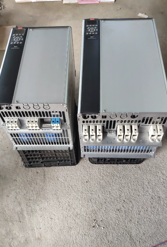

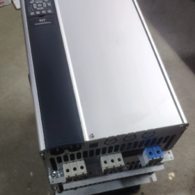
VLT AutomationDrive FC-302 de alto desempenho para uso geral Conversor de frequência
Pedido nº.: 131F7151
Decodificação do modelo segmento por segmento
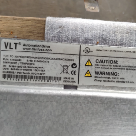
FC-302 P55K T5 E20 H2 B G XXXX SXXXX AXBXCXXXXDX
| Campo | Significado | Descrição |
| FC-302 | Série de produtos | VLT AutomationDrive FC-302, com controle de movimento, Parada segura, suporta aplicações do tipo servo |
| P55K | Classificação de potência | 55 kW / 75 HP |
| T5 | Especificação da fonte de alimentação | 3-fase 380‑500 Vca |
| E20 | Proteção de entrada | Estrutura aberta IP20, instalação em gabinete |
| H2 | Filtro RFI | Filtro EMC industrial classe C3 (2segundo ambiente, uso no chão de fábrica) |
| B | Chopper de freio | Chopper de freio integrado, resistor de freio conectável |
| G | Painel do Operador | Painel gráfico chinês LCP102 (mostrar & teclado) |
| XXXX | Revestimento de PCB / Opção de energia | X = PCB padrão não revestido, sem opções extras de fonte de alimentação |
| XXXXXX | Revisão de Software | Versão mais recente do firmware padrão de fábrica |
| MACHADO | Opção Slot A | Sem placa de comunicação A‑slot (slot A vazio; Profinet, EtherNet‑IP etc.. pode ser reformado) |
| BX | Opção Slot B | Sem placa de expansão de slot B |
| Experiência do cliente | Opção Slot C | Sem placa de controle de movimento MCO slot C |
| DX | Opção Slot D | Sem placa opcional de slot D |
Especificações elétricas principais
Potência nominal: 55 kW
Entrada: 3-fase 380-500V CA
Corrente de saída contínua: 106 UM
Sobrecarga: 160 % por 1 minuto (modo de alta sobrecarga)
Tamanho do chassi: C4
Componentes integrados: Reator de link CC, helicóptero de freio, Filtro RFI Classe C3
Protocolo padrão: Modbus-RTU; nenhuma placa de comunicação adicional instalada
Função de segurança: Terminal de hardware Safe-Stop
Temperatura ambiente: Classificação total a 40°C; desclassificar acima até máx. 50°C
Resumo da configuração principal
✅ 55kW, 380-500 V, Quadro aberto IP20
✅ Chopper de freio integrado, compatível com resistor de freio
✅ Equipado com painel de operação gráfico LCP-102
✅ Filtro EMC industrial classe C3, reator de link CC integrado
❌ Sem Profinet / EtherNet-IP ou outras placas fieldbus; pode ser adaptado através de slots A/B
❌ Sem placa de controle de movimento MCO
Aplicações Típicas
Fãs, bombas, extrusoras, transportadores, misturadores, fusos de máquinas-ferramenta. Suporta vetor de circuito fechado, modos de malha aberta e servo; adequado para aplicações com energia de frenagem regenerativa.
Peça sobressalente & Dicas de substituição
- Se o chopper de frenagem não for necessário: mude B para X; o número do pedido será diferente.
- Para Profinet: opção de ajuste AL (MCA120); para Ethernet-IP: opção de ajuste AN (MCA121).
- Mesma classificação de potência sem painel: substitua G por X, o modelo se torna FC-302P55KT5E20H2BXXXXSXXXXAXBXCXXXXDX
FC-302P55KT5E20H2BGXXXXSXXXXAXBXCXXXXDX
55 kW / 380-500 IP20, chopper de freio embutido, Filtro EMC classe C3, Painel gráfico chinês LCP102; sem cartão de comunicação, sem placa de controle de movimento MCO.
- Notas essenciais sobre fiação (DESLIGAR; permitir um tempo de descarga mínimo de 20 minutos para o barramento CC)
Circuito de alimentação principal
| terminal | Função | Observações |
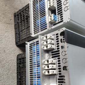
| L1/L2/L3 | 3entrada de fase 380‑500 V | NÃO troque com terminais de motor U/V/W |
| U/V/W | Saída do motor | Conecte ao motor trifásico; cabo blindado recomendado |
| BR+ / BR‑ | Resistor de freio | Para chopper de frenagem integrado; conecte o resistor de freio aqui, NÃO conecte aos terminais do barramento CC |
| +DC /-DC | Barramento de link CC | Usado para sistemas multidrive de barramento CC comum; deixe desconectado para operação padrão |
| Educação Física | Terra protetora | Aterramento confiável obrigatório |
Sugestão de dimensionamento de cabo para 55kW: cabo de alimentação ≥16mm²; cabo do motor ≥16mm²; cabo do resistor de freio ≥10mm².
Conexões obrigatórias do circuito de controle (falha ou inibição do inversor se ignorado)
- STO Safe-Torque-Off: terminal curto 12 para 37. Sem curto-circuito, saída do inversor é inibida. Para circuitos de segurança externos, conectar contatos de segurança em série.
- Terminal costeiro 27 está ativo de fábrica: se a parada por inércia não for necessária: definir parâmetro 5-12 = 0 (sem função). Para manter de costa a parada: curto 12-27.
- Terminais 12/13: saída interna de +24V (máx. 200mA); terminal20 = terra comum da entrada digital.
- Entradas analógicas: 53 (0-10 Tensão V); 54 (4-20 mA). Os dip-switches de hardware selecionam a tensão / modo atual.
- Terminais 68/69: RS485 Modbus-RTU; 68 =UMA, 69 = B.
Exemplo de lógica start-stop baseada em terminal
18 (DE): Começar (parâmetro5-10=Iniciar)
19 (DE): Reverter (parâmetro5-11=Reverso)
54: 4-20 referência de frequência mA
Relé 01-02-03: configurável para Executar / Sinalização de falha.
Conselhos práticos: ligue sem motor primeiro e verifique o status de E/S. Para comissionamento, desacoplar o acoplamento do motor e testar em baixa velocidade.
- Procedimentos de redefinição de fábrica
Método 1: Inicialização recomendada (mantém horas de funcionamento e configurações de comunicação)
- Menu Principal → 14-Funções Especiais → 14-22 Modo de operação
- Selecione 2 Inicialização → pressione OK
- Desconecte a alimentação principal; espere até o painel ficar totalmente escuro; reaplicar energia
- A80 Aparece a mensagem informativa “Drive inicializado” (não é uma falha); pressione Redefinir.
Método 2: Inicialização completa completa (todos os parâmetros apagados)
- Desligar; espere o painel apagar.
- Manter status + Menu Jogar + OK chaves juntas, em seguida, ligue a alimentação principal.
- Continue segurando por 5s e depois solte. A redefinição completa de fábrica é concluída ao ligar.
Dica de backup de parâmetros: 0-50 Copiar LCP → selecionar 1 Copie todos os parâmetros para o LCP. O painel pode armazenar parâmetros para download em unidades idênticas. NÃO copie parâmetros em diferentes classificações de potência.
- Principais parâmetros de comissionamento (unidade equipada com chopper de freio integrado)
| Parâmetro | Descrição | Configuração sugerida |
| 1-01 | Princípio de controle motor | VVCplus / Vetor de fluxo. Motor assíncrono: VVCplus; alto torque em baixa velocidade: selecione vetor de fluxo |
| 1-20~1-26 | Dados da placa de identificação do motor | Insira a potência da placa de identificação, tensão, atual, freqüência, velocidade exatamente |
| 1-29 | Ajuste automático do motor AMA | AMA estático; realizar com carga mecânica desacoplada |
| 2-10 | Função de freio | Habilitar chopper de frenagem integrado → 1 Habilitar |
| 2-11 | Valor Ohmico do resistor de freio | Insira o valor real do resistor para proteção térmica |
| 2-12 | Classificação de potência do resistor de freio | Classificação de potência do resistor de entrada para ativar a proteção do modelo térmico do resistor |
| 3-41/3-42 | Tempo de aceleração/desaceleração | Aumente a desaceleração para cargas de alta inércia para evitar sobretensão AL-16 |
| 5-10/5-11 | Funções de entrada digital | Configurar start-stop, comandos de direção |
Aviso do chopper de freio: resistores de baixo ohm em curto-circuito ou subestimados destruirão o chopper de frenagem. Sempre preencher 2-11 & 2-12 para proteção térmica.
- Lista de verificação de inspeção de entrada para FC-302-55kW usado (Quadro C4)
Inspeção visual
- PCB: verifique se há entrada de água, corrosão ou marcas de queimadura. Examine o caminho do ar de resfriamento e o ventilador em busca de poeira pesada. Gire manualmente o ventilador para rotação livre, não gruda.
- Terminais de energia: verifique se há arco / dano de queimadura. Verifique a sequência do modelo da placa de identificação: FC-302P55KT5E20H2B G……, pedido nº 131F7151.
- Teste todas as teclas no painel gráfico do LCP102.
Testes de multímetro estático de desligamento (descarga total do barramento CC obrigatória)
- Estágio retificador: medir adiante / queda reversa do diodo L1/L2/L3 contra +DC /-DC.
- Estágio IGBT: medir U/V-W versus +DC, -CC. As leituras trifásicas devem ser bem combinadas; grande desvio indica falha do módulo.
- Circuito de freio: testar BR+ / Transistor BRchopper para quebra de curto-circuito.
- Confirme que não há curto-circuitos entre terminal de controle e terra.
Teste de inicialização sem carga (motor desconectado)
- Ligado, verifique se não há falhas ativas. Ler horas de execução 15-00; inspecionar o registro do histórico de falhas 15-30.
- Execute a redefinição de fábrica e depois o ajuste automático do AMA. Execute 0-50 Hz sem carga; verifique o equilíbrio da tensão de saída trifásica. Desequilíbrio aponta para IGBT / danos na placa de acionamento.
- Teste funcional do chopper de freio: definir um tempo de desaceleração curto para induzir a regeneração; observe o aumento da tensão do barramento CC e a ativação do freio.
- Teste STO: abrir 12-37 link → falha STO aparece; recurte para limpar.
- Teste completo ponto a ponto para todas as entradas digitais e saídas de relé.
Teste acoplado ao motor
Desconecte a carga mecânica. Ligue o motor, verifique a corrente trifásica balanceada, sem vibração ou ruído anormal. Alta sobrecarga 160% / 1 meu teste: exercite-se com cautela.
Itens de falha comuns: desgaste do ventilador, desvio do sensor de corrente, danos no helicóptero de freio, Falhas no circuito de segurança STO, capacitores eletrolíticos envelhecidos. Alarmes típicos: AL13 Sobrecorrente, AL16 Sobretensão, AL29 Excesso de temperatura do dissipador de calor, Falha AL-8 STO.
- Seleção alternativa de fabricação nacional chinesa (55 vetor de alto desempenho kW, 380-500 V)
Recursos do FC-302: controle de vetor de fluxo, assíncrono & Suporte PMSM, reator de link CC integrado, chopper de freio embutido, cartões fieldbus expansíveis, STO Safe-Torque-Off. Verifique a correspondência de recursos antes da substituição.
| Marca & Modelo | Principais recursos de correspondência | Observações |
| Inovação MD380‑T55‑G | Abrir- / vetor de malha fechada; Compatível com STO; Profinet / EtherCAT expansível; unidade de freio opcional | Torque constante industrial de uso geral. Confirme a disponibilidade do chopper de freio para o seu projeto. |
| INVT CHV190‑055G‑4 | Vetor de alto desempenho; assíncrono / Suporte PMSM; barramento de campo expansível; STO | Para extrusoras, transportadores, misturadores; unidade de freio opcional integrada ou externa |
| Delta CH2000-55kW | Controle vetorial de fluxo; Segurança STO; cartões de comunicação expansíveis | Aplicações para serviços pesados, boa compatibilidade de substituição |
Advertências sobre substituição:
- O FC-302 original possui reator DC-link integrado. Muitas alternativas domésticas omitem isso; adicionar reator CC externo para locais com condições de rede de alta harmônica.
- A unidade original inclui chopper de freio de opção B integrado. Confirme se a unidade alternativa possui chopper de frenagem integrado ou planeje uma unidade de frenagem externa.
- STO Safe-Torque-Off pode ser uma placa opcional para alguns drives domésticos; não se esqueça de máquinas relacionadas à segurança.
- Comunicações: a unidade base não possui placa fieldbus (MCA120 Profinet adaptável). Confirme os requisitos de interface de barramento para unidade de substituição.
- Guia rápido de solução de problemas de falhas
- A unidade não funciona; alarme AL-8: inspecionar o circuito STO (12-37 curto-circuito / continuidade do contato de segurança).
- Alarme relacionado a parada por inércia: ou curto 12-27 ou definir parâmetro 5-12 para não funcionar.
- Sobretensão de desaceleração AL16: ① prolongar o tempo de rampa de desaceleração; ② confirme o chopper de freio ativado; ③ validar o valor do resistor de freio & classificação de potência.
- AL29 Sobretemperatura do dissipador de calor: limpar o acúmulo de poeira, inspecionar ventilador, reduzir a frequência da portadora, limitar a temperatura ambiente sustentada ≤40°C.
Danfoss FC-302P55KT5E20H2BGXXXXSXXXXAXBXCXXXXDX Especificações detalhadas completas
Série: VLT® AutomationDrive FC-302; Pedido nº.: 131F7152 (B = chopper de frenagem integrado, G = painel gráfico chinês LCP102)
Tamanho do quadro: C4; Estrutura aberta para montagem em gabinete IP20; 3-fase 380-500V; 55 kW / 75 HP; reator de link CC integrado, Classe C3(A2) Filtro RFI, chopper de freio embutido; sem placas opcionais A/B/C/D; PCB não revestido padrão.
- Principais classificações de entrada de fornecimento
| Item | Especificação |
| Tensão de entrada | 3-fase 380‑500 Vca, tolerância -10% ~ +10% |
| Frequência de entrada | 50/60 Hz ±5% |
| Corrente de entrada nominal | 112 UM (@400V nominal) |
| Reator de link CC integrado | ✅ Padrão. Atenua os harmônicos da rede; atende IEC61000‑3‑12 |
| RFI / Filtro EMC | H2 = Classe C3(A2), 2ambiente industrial. Somente aplicação no chão de fábrica; não para locais residenciais |
| Desempenho do fator de potência | Alto fator de potência fundamental > 0,98 via reator de link CC |
| Tratamento de abandono de suprimentos | Função de passeio de tensão configurável |
- Saída do motor: Poder, Atual & Sobrecarga (Quadro C4, 55 kW)
| Item | Valor |
| Classificação de potência contínua | 55 kW / 75 HP |
| Corrente de saída contínua de alta sobrecarga | 106 UM (380-440V); 105 UM (441-500V) |
| Sobrecorrente intermitente de alta sobrecarga | 160 % × Entrada = 169A, 60 duração, uma vez por ciclo de 10 minutos |
| Corrente Contínua de Sobrecarga Normal | 147 UM (380-440V) / 130 UM (441-500V) |
| Taxa de sobrecarga de sobrecarga normal | 110 %, 60 duração |
| Faixa de tensão de saída | 0 até tensão de entrada e alimentação |
| Faixa de frequência de saída | 0-1000Hz |
| Frequência portadora PWM | Padrão de fábrica 4kHz; ajustável 2‑16kHz; reduzir a potência em frequências portadoras mais altas |
| Algoritmos de Controle | VVCplus, vetor de fluxo em malha aberta/fechada, motor síncrono de ímã permanente, modo servo |
| Mecanismo de ajuste automático AMA | AMA estático e AMA rotativo suportado |
Orientação de aplicação: Alta sobrecarga para extrusoras, misturadores, guinchos. Sobrecarga normal para cargas de torque quadrático da bomba do ventilador.
- Especificações do circuito de freio (Chopper de freio integrado na opção B)
| Item | Especificação |
| Chopper de freio | ✅ Integrado a bordo via BR+ / Terminais BR; unidade de freio externa desnecessária |
| Potência máxima de freio | 110 pico de kW para este quadro de 55 kW |
| Resistência mínima permitida do resistor de freio | 13 Ω mínimo. Nunca use resistores de valor inferior; risco de destruição do helicóptero |
| Proteção térmica do resistor de freio | Modelo térmico de software através dos parâmetros 2-11 valor do resistor; 2-12 classificação de potência do resistor |
| Tensão operacional do barramento CC | 540-675 V típico; limite de ativação do chopper de frenagem 785 V para sistemas de 400 V |
| Compatibilidade com barramento CC comum | +Terminais CC /-CC suportam arquitetura de sistema de barramento CC comum multi-drive |
- Funções relacionadas à segurança
- STO Safe-Torque-Off (terminais com fio 12-37), PLd / Classificação SIL2. Inibição de ativação IGBT em nível de hardware; não pode ser substituído por software.
- Parada por inércia via terminal de entrada digital 27.
- Proteção térmica do motor: Relé térmico eletrônico ETR; PTC / Entradas do sensor de temperatura KTY84.
- Especificações da interface de E/S (Painel de controle)
Entradas Digitais DI (6 total de canais)
Nível lógico24V, PNP / Compatível com NPN. Impedância de entrada ~2kΩ. Alimentação on-board de 24V máx. 200mA.
Terminais: 18,19,27,29,32,33; terminal de referência comum20.
Saídas digitais DO (2 canais de coletor aberto)
24 V, corrente máxima de dissipação de 40mA.
Saídas de relé (3 relés)
01-02-03: AC250V, 2 UM; 04-05-06; 07-08-09. Configurável para execução, Falta, Sinalização de alarme.
IA de entradas analógicas
AI53: 0-10 Entrada de tensão V.
AI54: dip-switch de hardware selecionável 0-10V / 4-20 mA. Impedância de entrada: modo de tensão10kΩ; modo atual200Ω.
Saída Analógica AO
AO42: 0-10 V, máx. 1mA. Pode produzir frequência, corrente do motor, torque etc..
Interfaces de comunicação
Hardware padrão: RS485 Modbus-RTU (terminais68A, 69B).
SlotsA/B/C/D vazios conforme entregues. Opções compatíveis com retrofit: MCA120 (Profinet), MCA121 (Ethernet-IP), MCA111 (DeviceNet), Placa de controle de movimento MCO305.
- Dimensões Mecânicas, Peso & Classificações Ambientais (Quadro C4 IP20)
| Item | Valor |
| Altura H | 1300 milímetros |
| Largura L | 420 milímetros |
| Profundidade D | 386 milímetros |
| Peso líquido | 46.4 kg |
| Peso bruto de envio | 49.5 kg |
| Método de resfriamento | Resfriamento a ar forçado; módulo de ventilador substituível; caminho do fluxo de ar do canal traseiro |
| Montagem | Somente IP20 para montagem em gabinete, não para instalação direta em campo exposto. Montagem em gabinete compacto lado a lado permitida. |
Condições Ambientais de Operação
Ambiente operacional: -10 °C ~ +40°C potência máxima. Desclassificar a saída > 40°C; temperatura operacional máxima absoluta50°C (desclassificado).
Armazenar & temperatura de transporte: -25 °C ~ +65°C.
Altitude: classificação completa ≤1000m acima do nível do mar; reduzir 1% da potência de saída por elevação adicional de 100 m.
Revestimento de PCB: XXXX = PCB padrão não revestido. Especifique a variante de PCB revestida para ambientes com gases corrosivos.
- Perda de energia & Eficiência
Perda total de potência em carga nominal: aprox. 1020W.
Eficiência: 98 % no ponto operacional nominal.
- Painel do Operador & Programas
LCP102 display gráfico multilíngue com teclado chinês (Opção G). Recurso de backup de cópia de parâmetros; suporte de cabo de extensão de painel para montagem remota.
Identificador de firmware SXXXX = firmware de produção de fábrica mais recente.
Software de comissionamento MCT-10: Upload conectado ao PC / parâmetros de download, gravação de registro de falhas.
- Proteção de hardware & Eventos de alarme
Sobrecorrente, sobretensão, subtensão, falha à terra, curto-circuito de saída, superaquecimento do dissipador de calor, sobrecarga do motor, Parada segura STO, superaquecimento do resistor do freio, falha do ventilador, falha de comunicação.
- Nova verificação completa do código do modelo
FC-302 P55K T5 E20 H2 B G XXXX SXXXX A X B X C XXXX D X
FC-302: família de produtos
P55K: 55 potência kW
T5: 3-alimentação de fase 380-500V
E20: Construção de estrutura aberta IP20
H2: Filtro RFI Classe C3
B: Chopper de freio integrado (principal característica desta unidade)
G: Painel de operação gráfico LCP-102
XXXX: PCB padrão não revestido, sem opções de energia auxiliar
XXXXXX: firmware padrão de fábrica
MACHADO / BX / Experiência do cliente / DX: slots A/B/C/D vazios, nenhum fieldbus ou placas de controle de movimento instaladas.
Nota importante: O número de peça 131F7151 corresponde à variante sem chopper de freio e sem painel de operação (B=X, G=X). A atual unidade completa usa o número de pedido 131F7152 (Opções B+G).





NH42-63-318x560.png "Chaves de transferência automática tipo PC CHINT (ATS)NH42-63/4SZ")



