 Contator,disjuntor,sensor,Codificador,CLP,Conversor

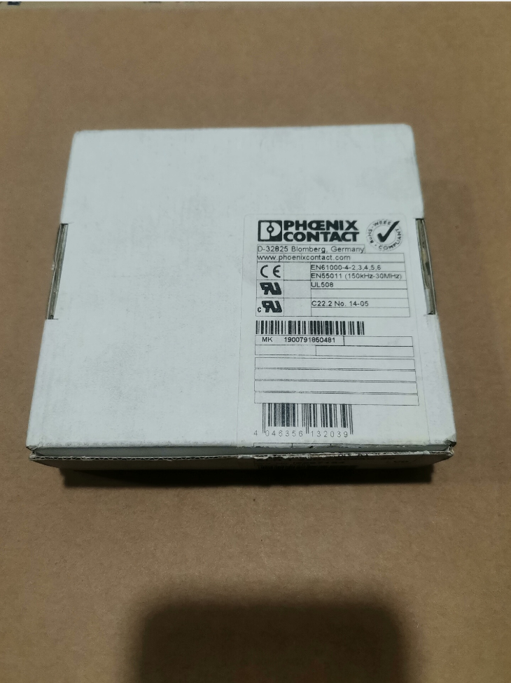

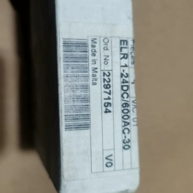
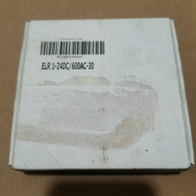
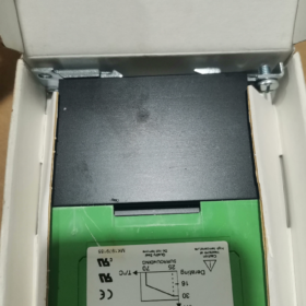
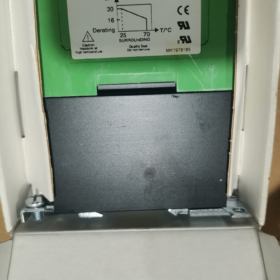
Contato Phoenix ELR1-24DC-600AC-30, Número do pedido. 2297154
- Decodificação completa do modelo
Modelo: ELR1-24DC-600AC-30
- ELR1: Série → ELR1 monofásico
- 1 carga eletrônica monofásica relé
- (contator de estado sólido, interruptor sem contato, adequado para cargas de motor)
- 24CC: Fornecimento do lado de controle / tensão de acionamento: 24 Em DC
- 600AC: Tensão nominal de operação do circuito principal: CA 0…600 V
- 30: Corrente nominal de operação contínua: 30 UM
- 2297154: Único oficial Fênix Número do pedido de contato
Nome completo do produto: Contator de estado sólido ELR 1-24DC/600AC-30
- Parâmetros elétricos principais
| Item | Especificação |
| Número do pedido. | 2297154 |
| Tensão de controle | 24 Em DC (faixa permitida: 19.2~30V CC) |
| Tensão do Circuito Principal | CA 0~600 V, 50/60 Hz |
| Corrente de carga nominal | 30 UM (carga resistiva) |
| Tipo de carga aplicável | Cargas CA monofásicas; fãs, elementos de aquecimento, pequenos motores monofásicos |
| Componente de comutação | Triac bidirecional (sem contato) |
| Frequência de comutação | Muito superior aos contatores mecânicos, adequado para troca frequente |
| Isolamento | Isolamento optoeletrônico; isolamento galvânico entre o circuito de controle e o circuito principal |
| Tipo de montagem | 35 mm montagem em trilho DIN |
| Conexão | Conexão de terminal de parafuso |
| Temperatura ambiente de operação | -20 ℃~ +60 ℃ (desclassificação exigida acima 40 ℃) |
- Principais recursos
✅ Sem contatos mecânicos, sem arcos elétricos, baixo ruído, vida útil prolongada, ideal para operação start-stop frequente
✅ Circuito de absorção de sobretensão integrado para suprimir surtos de carga indutiva
⚠️ Restrição Importante: Relé monofásico de estado sólido. Não é para controle direto de cargas trifásicas; aplicável apenas a cargas CA monofásicas
⚠️ Para cargas indutivas (motores, bobinas), é necessária margem atual suficiente; 30% desclassificação atual é recomendada
- Alfinete / Definição de terminal
A1 / A2: Terminais de controle para 24 Em DC
A1(+), A2(-)
eu / N: Terminais de entrada CA do circuito principal
FORA: Terminal de saída de carga
- Cenários típicos de aplicação
Controle de resistências elétricas dentro de gabinetes de controle industriais
Partidas e paradas frequentes de ventiladores monofásicos e motores transportadores
Loops de controle de temperatura para máquinas de embalagem, equipamentos de teste e fornos
Cargas CA que exigem baixo ruído, comutação sem manutenção
- Alternativa & Referências da mesma série
- Variantes de corrente mais baixa na mesma série: ELR1-24DC-600AC-10 (10 UM), ELR1-24DC-600AC-20 (20 UM)
- Para interruptores de estado sólido trifásicos: Consulte a série ELR3 (contatores de estado sólido trifásicos)
- Equivalentes do concorrente: Série Schneider SSP, Relés de estado sólido monofásicos Omron G3PA
- Notas de aquisição
Distinguir sufixos de modelo: Não confunda ELR1 (monofásico) / ELR3 (trifásico)
Usar número do pedido 2297154 estritamente para evitar a entrega de outras classificações atuais
Componentes de estado sólido geram calor significativo; espaço suficiente para dissipação de calor é necessário para instalação densa dentro de gabinetes
Cenários de aplicação — Phoenix Contact ELR 1-24DC/600AC-30 (Pedido nº 2297154)
Recapitulação da visão geral do produto
Contator monofásico de estado sólido (SSR sem contato)
Controlar: 24 Em DC; Circuito principal: ≤600 V CA, avaliado 30 UM; montado em trilho DIN; isolamento optoeletrônico; saída triac bidirecional; otimizado para comutação frequente de cargas CA monofásicas
Principais vantagens: Sem arco, sem desgaste mecânico, baixo ruído, comutação frequente de alta velocidade. Limitação: Autoaquecimento, redução de corrente obrigatória para cargas indutivas.
Premissa Crítica: Suporta apenas cargas CA monofásicas; não pode acionar diretamente motores trifásicos
- Cenários Industriais Padrão Geral
1.1 Cargas de aquecimento resistivas (Aplicação mais comum)
- Controle de tubos de aquecimento em fornos, fornos de túnel e equipamentos de processamento térmico
- Circuitos de aquecimento para moldagem por injeção e barris extrusores
- Termostatos industriais, sopradores de ar quente e aquecedores elétricos de dutos
- Elementos de aquecimento de máquinas de selagem a quente e equipamentos de estampagem a quente em máquinas de embalagem
✅ Vantagem: A comutação contínua de alta frequência PID por controladores de temperatura desgasta rapidamente os contatos dos contatores mecânicos; ELR1 se adapta perfeitamente a esta condição de trabalho
1.2 Ventiladores Monofásicos & Bombas (Cargas Indutivas)
Requisito de aplicação: 25%~30% de redução de corrente para seleção de carga
- Ventiladores de refrigeração do gabinete de controle, exaustores industriais e ventiladores monofásicos canalizados
- Pequenas bombas centrífugas monofásicas, bombas de circulação de água e exaustores de fumos
- Unidades de fornecimento de ar para equipamentos de secagem
⚠️ Nota: Grande corrente de partida na partida do motor; carga real recomendada ≤20~22 A para o 30 Um modelo
1.3 Cargas de iluminação
- Bancos de lâmpadas halógenas de alta potência e conjuntos de lâmpadas de aquecimento infravermelho em oficinas
- Matrizes de iluminação de alta potência em laboratórios de teste
❌ Não recomendado: Drivers de LED e cargas de reatores eletrônicos (alta corrente de partida; Circuito amortecedor RC é recomendado)
- Aplicações de campo específicas do setor
▶ Máquinas de embalagem
- Controle de aquecimento para túneis termorretráteis
- Atuação de barras de vedação térmica na vertical / máquinas de embalagem horizontais
- Motores de acionamento monofásicos em linhas de transporte e sistemas de secagem por ar quente
▶ Plásticos & Máquinas de borracha
- Controle de haste de aquecimento para cada zona de temperatura de extrusoras e peletizadoras
- Controle start-stop de circuitos de aquecimento para controladores de temperatura de moldes
▶ AVAC & Equipamento de teste ambiental
- Aquecedores para câmaras de teste de alta e baixa temperatura e temperatura constante & câmaras de umidade
- Sistemas de circulação de ar quente para equipamentos de purificação
- Módulos de aquecimento de desumidificadores industriais
▶ Nova Energia & Linhas de produção de baterias de lítio
- Controle de aquecimento para fornos de secagem de eletrodos
- Dispositivos de ar quente para equipamentos de remoção de poeira
Vantagem: Sem faíscas para oficinas livres de poeira (o dispositivo em si NÃO é à prova de explosão; invólucro à prova de explosão é obrigatório para áreas perigosas)
▶ Comida & Equipamento Farmacêutico
- Sistemas de aquecimento elétrico para linhas de cozimento de alimentos e equipamentos de esterilização
- Unidades de secagem por ar quente para equipamentos de limpeza
Vantagem: A operação sem contato evita a geração de poeira metálica, atendendo aos requisitos de operação para salas limpas
▶ Equipamento de teste automatizado
- Comutação de cargas de alta potência em bancadas de teste antigas
- Dispositivos de comutação de carga CA ajustáveis em laboratórios
- Controle de cluster de bobinas solenóides CA de alta potência
- Cenários Inaplicáveis (Seleção de linhas vermelhas)
- ❌ Controle direto de motores assíncronos trifásicos (ELR1 é SSR monofásico; controla apenas uma fase. Estritamente proibido como interruptor trifásico principal. Selecione a série ELR3 para cargas trifásicas)
- ❌ Partida frequente de compressores monofásicos de alta potência (corrente de partida severa pode causar falha no triac)
- ❌ Aplicativos que dependem do dispositivo para sobrecarga de longo prazo & proteção contra curto-circuito (relés de estado sólido têm baixa capacidade de resistência a curto-circuitos; disjuntores / os fusíveis devem ser instalados a montante)
- ❌ Instalação externa desprotegida ao ar livre (deve ser instalado dentro de gabinetes de controle)
- ❌ Cargas indutivas de alta tensão e alta frequência sem circuitos amortecedores RC
- Configuração de suporte recomendada para implantação no local
- Cargas indutivas (motores, bobinas): Módulos de absorção paralelos Phoenix Contact RC para suprimir EMF
- Várias unidades montadas lado a lado em trilho DIN: Mantenha uma folga mínima ≥10 mm entre dispositivos adjacentes; redução de corrente necessária quando a temperatura ambiente do gabinete é> 45 ℃
- Proteção a montante: Implantar fusíveis gG; os disjuntores por si só não podem fornecer proteção confiável contra curto-circuito
- Componente preferido para sistemas de controle de temperatura PID; a frequência de comutação pode atingir vários ciclos por segundo, vida útil muito superior aos contatores mecânicos
Especificação de montagem - Phoenix Contact ELR 1-24DC/600AC-30 (2297154)
- Formulário de montagem padrão
Montagem padrão: Instalação snap-on em 35 mm trilho DIN (TH35-7,5)
- Clipe de travamento do trilho DIN integrado na parte traseira do dispositivo; não são necessários colchetes adicionais
- Orientação de montagem obrigatória: Instalação vertical (terminais voltados para cima/para baixo; aletas de resfriamento dispostas verticalmente)
❌ Montagem lateral horizontal & instalação invertida é proibida! A colocação horizontal bloqueia o resfriamento por convecção natural, levando ao desligamento por superaquecimento e danos ao triac.
- Montagem & Procedimentos de desmontagem
- Prenda o clipe superior no trilho DIN;
- Pressione o corpo principal até ouvir um som “clique” confirma que o clipe inferior trava no trilho;
- Remoção: Abra o clipe inferior com uma chave de fenda e levante o dispositivo para cima.
- Requisitos de liberação térmica (Crítico! 30 Contatores de estado sólido geram calor considerável)
Instalação única independente
Folga vertical (principal & fundo): ≥50 mm de espaço de ventilação
Folga lateral: ≥10 mm se o espaço adjacente estiver vago
Várias unidades montadas lado a lado no mesmo trilho DIN
Espaço mínimo entre dispositivos adjacentes: ≥10mm
É proibido um arranjo apertado com folga zero
Mantenha uma folga de ≥15 mm se a temperatura do gabinete for >40 ℃
Para instalação contínua em grande escala, é recomendado resfriamento de ar forçado através de ventiladores axiais do gabinete
- Especificação de fiação (Terminais de parafuso)
Atribuição de terminais
A1(+), A2(-): 24 Circuito de controle V CC
eu, FORA: Circuito principal para cargas CA monofásicas
Parâmetros de fiação
- Tipo de terminal: Terminais de parafuso anti-afrouxamento
- Condutores aplicáveis:
Fio sólido de núcleo único: 0.5~10 mm²
Fio flexível trançado: Terminais de crimpagem são recomendados
- Torque de aperto recomendado: 1.2~1,5 N·m
⚠️ Torque insuficiente → aquecimento excessivo; torque excessivo → deslizamento da rosca ou rachadura na base do terminal.
Sugestão de layout de fiação
Roteamento separado para cabos de controle (A1/A2) e cabos de alta potência (E/SAÍDA) para reduzir a interferência eletromagnética
Minimize o comprimento da fiação de energia para reduzir a queda de tensão e a geração de calor
- Condições Limites Operacionais Ambientais
- Local de instalação: Dentro dos gabinetes de controle, Classe de proteção IP20
❌ Exposição direta ao ar livre; evite poeira, umidade e condensação em contato com o dispositivo
- Temperatura operacional permitida: -20 ℃~ +60 ℃
A redução da corrente é obrigatória quando a temperatura ambiente é superior a 40 ℃
- Evite estas posições de instalação:
Diretamente acima dos transformadores, resistores de potência e outros componentes geradores de calor
Zonas mortas mal ventiladas dentro dos armários
Locais com forte vibração persistente (vibração contínua afrouxa os parafusos do terminal)
- Acessórios opcionais de dissipação de calor
Para operação contínua em plena carga em gabinetes fechados, Dissipadores de calor de alumínio montados em trilho DIN podem ser fixados na parte traseira do dispositivo para reduzir a temperatura da caixa.
Nenhum dissipador de calor fornecido como padrão; o resfriamento depende de aletas integradas na caixa para convecção natural.
- Operações estritamente proibidas
- Não suspenda o dispositivo por cabos; toda carga mecânica deve ser suportada pelo trilho DIN
- Não bloqueie as aletas de resfriamento nas laterais e na superfície traseira
- Não conecte múltiplas unidades ELR1 em paralelo para compartilhamento de corrente (resistência inconsistente causa distribuição desigual de corrente e desgaste)
- Não instale contatores / disjuntores firmemente adjacentes a contatores de estado sólido sem folga térmica
Descrição padrão para desenhos de engenharia
O ELR1-24DC/600AC-30 deve ser montado verticalmente em trilho DIN padrão TH35. Folga lateral entre dispositivos adjacentes ≥10 mm. Roteamento separado para circuitos de controle e potência. Torque de aperto dos terminais: 1.2~1,5 N·m. Garanta ventilação natural adequada para dissipação de calor.



NH42-63-318x560.png "Chaves de transferência automática tipo PC CHINT (ATS)NH42-63/4SZ")



