 Contator,disjuntor,sensor,Codificador,CLP,Conversor





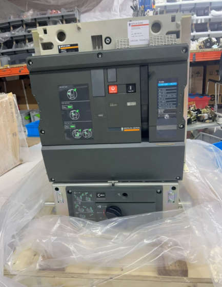
NT: MasterPact NT series disjuntor de ar (ACB, legacy model, descontinuado; replacement model MTZ1 06H2)
06: Tamanho do quadro 06, frame rated current 630A
H2: Breaking capacity class H2; Icu=50kA@440VAC, short-time withstand current Icw=50kA (1é), Class B selective protection
Parâmetros elétricos principais
| Item | Especificação |
| Frame rated current In | 630UM (a 40℃) |
| Tensão operacional nominal Ue | CA 690V, 50/60Hz |
| Tensão nominal de isolamento Ui | CA 1000V |
| Tensão nominal suportável de impulso Uimp | 12kV (1.2/50μs lightning impulse) |
| Capacidade final de interrupção de curto-circuito Icu | 50kA@440V; 42kA@690V |
| Número de pólos | 3P / 4P opcional |
| Tipo de construção | Fixo / Extração |
| Unidade de viagem | Frame supplied without trip unit, MicroLogic trip unit to be ordered separately |
| Padrões | CEI 60947-2, with isolating function |
Notas principais
- Status de descontinuação: NT series scheduled for end-of-sale by the end of 2025. Replacement model MTZ1 06H2, part number LV947203 (draw-out version)
- Parameter Clarification
Ue=690V: Maximum normal operating voltage
Ui=1000V: Tensão suportável de frequência de energia
Uimp=12kV: Tensão suportável de impulso relâmpago. NOT applicable for 12kV high-voltage switchgear, this is an insulation index for low-voltage ACB
- Aplicativo: Incoming feeder, bus tie and heavy-load outgoing feeder in low-voltage distribution systems, for industrial plants, data centers and marine power distribution; supports selective protection and coordination with upstream/downstream devices
- Reference Frame Part Numbers
NT06H2 3P Fixed: 47113
NT06H2 3P Draw-out: 47203
NT06H2 4P Fixed: 47119
Acessórios & Peças de reposição
Trip Units: MicroLógica 2.0 / 5.0 / 6.0 / 7.0 (sobrecarga, atraso de curto prazo, instantaneous and earth-fault protection)
Acessórios: Motor operating mechanism, contatos auxiliares, fault alarm contacts, closing coil, shunt trip coil, door interlock, phase barriers
Draw-out base: Mandatory independent cradle for draw-out version
Diretrizes para solução de problemas
- Falha ao fechar: Undervoltage coil de-energized, incomplete spring charging, cradle not in connected position, interlock blocking
- Unintended tripping: Check trip unit protection curve, falha de terra, harmonic distortion and temperature rise
- Teste de isolamento: Power frequency withstand test at Ui=1000V level; 12kV impulse withstand is type-test only, no on-site 12kV impulse test
Referência Alternativa Doméstica
Domestic MT06H2 (Schneider domestic MT series). Compatible breaking capacity and mounting dimensions for direct replacement.
Schneider MasterPact NT06H2 Air Circuit Breaker Technical Manual (Full Engineering Version, per original datasheet 0613CT0001)
Observações: NT series is legacy discontinued ACB, frame size NT06, Entrada=630A; breaking class H2; frame supplied without trip unit, MicroLogic trip unit to be ordered separately; standard IEC 60947-2, isolating function, Class B selective protection
Índice
- Visão geral do produto & Explicação do código do modelo
- Rated Electrical Parameters
- Parâmetros Mecânicos, Dimensões Gerais & Peso
- MicroLogic Trip Unit Selection
- Lista de acessórios & Secondary Terminal Definition
- Instalação & Requisitos de fiação
- Operação, Handling & Interlock Description
- Manutenção, Inspeção & Solução de problemas
- Condições ambientais
- Replacement Model Information
- Original Document Index
- Visão geral do produto & Explicação do código do modelo
1.1 Visão geral
MasterPact NT series low-voltage air circuit breakers for incoming feeders, bus ties and high-current outgoing feeders in 400/690V low-voltage distribution systems. NT06H2 maximum frame rating 630A, available in draw-out or fixed construction, spring charged operation, configurable with intelligent MicroLogic protection unit, supports remote signalling, metering and communication.
Lembrete importante: Ui=1000V (tensão nominal de isolamento), Uimp=12kV (lightning impulse withstand voltage). NOT 12kV high voltage circuit breaker, only for AC ≤690V low-voltage distribution.
1.2 Análise do modelo
NT: MasterPact NT series air circuit breaker
06: Tamanho do quadro 06, frame rated current 630A
H2: Breaking class H2; Icu=50kA@440VAC, Icw=50kA 1s, Class B selective
Números de peça:
NT06H2 3P Fixed: 47113
NT06H2 3P Draw-out: 47203
NT06H2 4P Fixed: 47119
1.3 Status do produto
NT series scheduled end-of-sale by end of 2025; replacement model MTZ1 06H2, part number LV947203 (prolongamento). Mounting dimensions and secondary interfaces fully compatible for direct replacement.
- Rated Electrical Parameters
| Item | Valor |
| Frame rated current In | 630UM (at 40℃ ambient) |
| Tensão operacional nominal Ue | CA 50/60 Hz, max 690V |
| Tensão nominal de isolamento Ui | 1000V |
| Tensão nominal suportável de impulso Uimp | 12kV (1.2/50μs lightning impulse) |
| Capacidade final de interrupção de curto-circuito Icu | 50kA@440V; 42kA@690V |
| Rated short-time withstand current Icw | 50o, 1é |
| Capacidade nominal de interrupção de serviço Ics | 100% de UTI |
| Selectivity class | Classe B (with short-time delay selective protection) |
| Isolating function | Complies with IEC60947-2 isolation requirement |
| Número de pólos | 3P / 4P opcional |
- Parâmetros Mecânicos, Dimensões Gerais & Peso
3.1 Resistência Mecânica
Vida mecânica: 20,000 operações (no-load make/break)
Vida elétrica (400V, Em): 10,000 operações
Spring charging: Manual charging / motor charging MCH optional
3.2 Dimensões Gerais (3P, unidade: milímetros)
Tipo fixo: W300 × H415 × D266
Tipo extraível (with cradle): W300 × H415 × D376
4P version width 360mm, height and depth unchanged
3.3 Peso
Fixed frame only: ≈32kg
Draw-out frame + cradle: ≈52kg
3.4 Three positions for draw-out version
- Connected Position: Main circuit and secondary circuit fully connected, operação normal
- Test Position: Main circuit disconnected, secondary circuit remains connected for protection test
- Disconnected Position: Main and secondary circuits fully disconnected, breaker can be withdrawn for maintenance
- MicroLogic Trip Unit Selection (Deve ser pedido separadamente, not included with frame)
| Modelo de unidade de viagem | Funções de proteção | Aplicação Típica |
| MicroLógica 2.0 | Long-time overload protection only | Isolador, overload-only protection |
| MicroLogic 5.0A | Long-time Ir, short-time delay Isd, instantaneous Ii | Incoming feeder, gravata de ônibus (mais comum) |
| MicroLogic 6.0A | All functions of 5.0A + proteção contra falha à terra | Critical incoming feeder requiring earth fault protection |
| MicroLogic 7.0A | 6.0UM + proteção de corrente residual + monitoramento harmônico | Centros de dados, sensitive loads |
Protection setting range: E (de longa data) 0.4~1×In; Isd short-time delay 0.5~10×In, delay 0.1/0.2/0.4s; Ii instantaneous 1~15×In.
- Lista de acessórios & Secondary Terminal Definition
5.1 Acessórios opcionais
- MCH: Charging motor AC220V / CC24V
- XF: Closing solenoid AC220V / CC24V
- MX: Bobina de disparo de derivação (abertura remota)
- Minnesota: Liberação de subtensão (MNu time-delayed undervoltage for auto-transfer application)
- DE: Contatos auxiliares (CB on/off status feedback)
- SDE: Fault trip contacts (signal for overload/short-circuit/earth fault trip)
- PF: Cradle position contacts (conectado / test / disconnected position)
- Phase barriers, intertravamento da porta do armário, mechanical interlock cables, padlock device
- ULP communication module: Modbus-RTU, remote signalling & medição
5.2 Secondary Terminal Definition
| Código | Nome | Terminais | Descrição |
| MCH | Charging motor | B1, B2 | Auto charging upon power-up; B1-B3 charged ready CH contact |
| XF | Closing coil | A1, A2 | Atuação de fechamento |
| MX | Viagem de manobra | C1, C2 | Remote opening |
| Minnesota | Liberação de subtensão | D1, D2 | Trip on loss of voltage, core component for auto-transfer |
| DE | Auxiliary position contact | 11-12 NC /11-13 NÃO | On/off status feedback |
| SDE | Fault trip contact | 81,82 | Protection action signal |
| PF | Cradle position contact | 251/252/254 | Draw-out position signal |
- Instalação & Requisitos de fiação
- Montagem: Instalação vertical vertical, ±5° tilt allowed; inverted mounting prohibited
- Conexão do circuito principal: Conexão frontal / rear horizontal / rear vertical connection; apply specified tightening torque for copper busbars to avoid overheating
- Secondary control wiring: 0.75~1.5mm² multi-core shielded cable; independent AC220V/DC24V control power supply for secondary circuit
- Teste de isolamento: Power frequency withstand test at Ui=1000V level; 12kV impulse withstand is type test only, no on-site 12kV impulse test
- Draw-out operation: Use dedicated crank for rack-in / rack-out; prohibit racking out breaker from connected position under live condition
- Operação, Handling & Interlock Description
7.1 Operation Procedure
- Carregando: Manual charging handle or MCH motor auto charging; charging complete, charged indicator lights on
- Fechando: Local front panel close pushbutton / XF remote close; verify interlock conditions before closing
- Abertura: Local open pushbutton / MX remote opening / automatic protection tripping; after fault trip, fault reset button must be manually reset before re-closing
7.2 Intertravamento (Two-incoming one bus tie scheme)
Intertravamento mecânico: Steel cable mechanical interlock, physically prevents simultaneous closing of three ACBs
Electrical interlock: Close circuit wired in series with normally closed contacts of other breakers for double protection
Cradle position interlock: Closing circuit blocked when not in connected position, closing prohibited
Fault trip interlock: Auto-transfer closing logic blocked upon SDE contact activation
- Manutenção, Inspeção & Solução de problemas
8.1 Manutenção Periódica
Semi-annual: Check charging status, on/off indication, contact temperature rise, tightness of secondary wiring
Anual: Limpeza de poeira, insulation inspection, trip unit test (using MicroLogic test cable)
Revisão (todo 5 anos): Disassemble to inspect main contacts and arc chamber, mechanical lubrication, mechanical life verification
8.2 Solução de problemas típica
- Falha ao fechar
Incomplete charging; undervoltage MN coil de-energized; cradle not in connected position; interlock blocked; fault trip not reset
- Unintended tripping
Verify protection curve; falha de terra; harmonic overload; loose wiring with overheating; voltage dip triggering MN undervoltage trip
- Charging failure
No power supply to MCH motor; jammed charging mechanism; damaged charged-ready contact
- Nenhuma saída de sinal de falha
Wrong SDE auxiliary contact wiring, contatos queimados
- Condições ambientais
Temperatura ambiente operacional: -5℃ ~ +70 ℃; desclassificação necessária acima de 40℃
Temperatura de armazenamento: -40℃ ~ +85 ℃
Umidade relativa: ≤95% (sem condensação)
Altitude: ≤2000m; derating and insulation correction required above 2000m
Grau de proteção: Device IP30; IP40 with cabinet door closed
Grau de poluição: 3
- Replacement Model Information
NT06H2 → MTZ1 06H2
Quadro 630A, UTI=50kA, compatible MicroLogic trip unit
Dimensões de montagem, primary busbar and secondary terminals fully compatible, no cabinet modification required for in-panel retrofit
Supports ECOSTRUXURE Power software commissioning, upgraded communication interface
Schneider MasterPact NT Full Series Model List (IEC Version, Discontinued ACB, Frame 630~1600A)
Regra de nomenclatura: NT + Frame Code + Aula de última hora
Frame Code: 06=630A; 08=800A; 10=1000A; 12=1250A; 16=1600A
Aula de última hora: N1 / H1 / H2 / L1; Construção: Fixo / Extração; Poles 3P/4P; Frame without trip unit, MicroLogic to be ordered separately
Common Base Parameters: Ui=1000V, Uimp=12kV, Ue max AC690V, Class B selective protection
Breaking Class Definition (440V, Icu ultimate breaking capacity)
N1: 35o
H1: 42o
H2: 50o (same class as NT06H2)
L1: 130o (current-limiting type, application for high short-circuit capacity)
NT Full Model List
| Quadro | Frame In | Aula de última hora | Modelo Completo | Icu@440V | Icw(1é) | Typical 3P Fixed Part No. |
| NT06 | 630UM | N1 | NT06N1 | 35o | 35o | 47111 |
| NT06 | 630UM | H1 | NT06H1 | 42o | 42o | 47112 |
| NT06 | 630UM | H2 | NT06H2 | 50o | 50o | 47113 |
| NT06 | 630UM | L1 | NT06L1 | 130o | 50o | 47114 |
| NT08 | 800UM | N1 | NT08N1 | 35o | 35o | 47121 |
| NT08 | 800UM | H1 | NT08H1 | 42o | 42o | 47122 |
| NT08 | 800UM | H2 | NT08H2 | 50o | 50o | 47123 |
| NT08 | 800UM | L1 | NT08L1 | 130o | 50o | 47124 |
| NT10 | 1000UM | N1 | NT10N1 | 35o | 35o | 47131 |
| NT10 | 1000UM | H1 | NT10H1 | 42o | 42o | 47132 |
| NT10 | 1000UM | H2 | NT10H2 | 50o | 50o | 47133 |
| NT10 | 1000UM | L1 | NT10L1 | 130o | 50o | 47134 |
| NT12 | 1250UM | N1 | NT12N1 | 35o | 35o | 47141 |
| NT12 | 1250UM | H1 | NT12H1 | 42o | 42o | 47142 |
| NT12 | 1250UM | H2 | NT12H2 | 50o | 50o | 47143 |
| NT12 | 1250UM | L1 | NT12L1 | 130o | 50o | 47144 |
| NT16 | 1600UM | N1 | NT16N1 | 35o | 35o | 47151 |
| NT16 | 1600UM | H1 | NT16H1 | 42o | 42o | 47152 |
| NT16 | 1600UM | H2 | NT16H2 | 50o | 50o | 47153 |
| NT16 | 1600UM | L1 | NT16L1 | 130o | 50o | 47154 |
Draw-out part number: adicionar 10 to the last digit. Example NT06H2 3P Draw-out:47203; 4P fixed part number +6 (NT06H2 4P Fixed 47119)
Derivative Isolator Models (HA version)
NTxxHA: Isolador (without trip unit, IEC60947-3)
NT06HA / NT08HA / NT10HA / NT12HA / NT16HA
Compatible Trip Unit List (Universal for full NT series)
MicroLógica 2.0: Long-time overload only
MicroLogic 5.0A: De longa data + atraso de curto prazo + instantâneo (preferred for incoming / gravata de ônibus)
MicroLogic 6.0A: 5.0UM + proteção contra falha à terra
MicroLogic 7.0A: 6.0UM + proteção de corrente residual + harmonic measurement
Replacement Cross Reference Table (NT → MTZ1)
| Legacy NT Model | Replacement MTZ1 Model |
| NT06N1 | MTZ1 06N1 |
| NT06H1 | MTZ1 06H1 |
| NT06H2 | MTZ1 06H2 |
| NT06L1 | MTZ1 06L1 |
| NT08~NT16 follow same rule | MTZ1 08 /10 /12 /16 + aula de última hora |
Selection Remarks
- NT series fully discontinued, not recommended for new projects; MTZ1 can be used for spare parts replacement for existing projects with compatible primary and secondary interfaces.
- L1 current-limiting type for systems with extremely high short-circuit current, custo mais alto; H2 is preferred for normal incoming feeder and bus tie.
- Rated current can be derated within the same frame by changing current sensor inserts, por exemplo. NT06 frame available with 400A/500A/630A sensors.





NH42-63-318x560.png "Chaves de transferência automática tipo PC CHINT (ATS)NH42-63/4SZ")



