

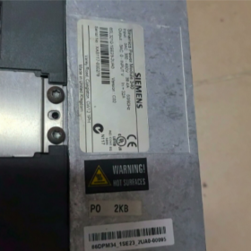
6SL3210-1SE23-2UA0
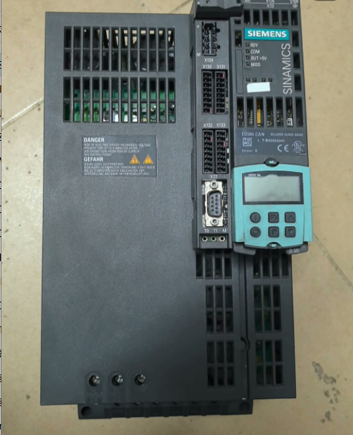
Model 6SL3210-1SE23-2UA0 is a PM340 power module belonging to Siemens’ SINAMICS S120 series. It is designed for 380-480V three-phase input, with a rated output of 15kW/32A, frame size FSC, IP20 protection class, and internal air cooling. The module has been discontinued since October 1, 2019, and is now available only as a spare part.
Core Electrical Parameters
| Parâmetro | Value | Observações |
| Input | 3CA 380-480V 10%, 47-63Hz | Three-phase input |
| Potência de saída nominal | 15kW | Suitable for 380-480V motors |
| Rated Output Current (IN) | 32UM | Continuous operation |
| HO Rated Current | 27UM | Heavy-duty mode |
| S6 40% Duty Cycle Current | 37.1UM | Intermittent cyclic operation |
| Maximum Output Current | 52UM | Short-time overload |
| Pulse Frequency | 4kHz | Standard value |
| Servo Control Output Frequency | 0-330Hz | Suitable for servo applications |
| Classe de Proteção | IP20 | Cabinet installation |
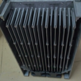
Structural and Physical Characteristics
| Item | Specification |
| Frame Size | FSC |
| Dimensões (W×H×D) | 188.4mm × 333.4mm × 185.0mm |
| Net Weight | 6.5kg |
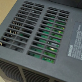
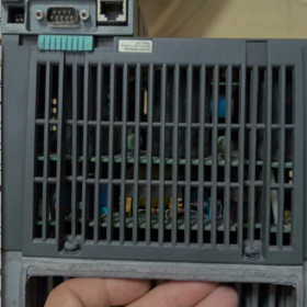
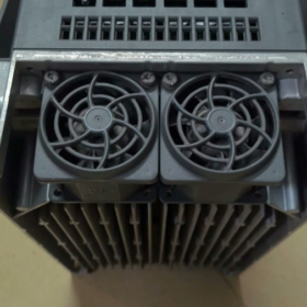
| Método de resfriamento | Internal air cooling |
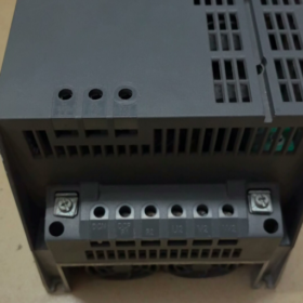
| Método de fiação | Screw terminals, line-side compatible with 2.5-16mm² cables |
Key Information and Compatibility
- Life Cycle: Discontinued (October 1, 2019), available only as a spare part. For alternative solutions, refer to Siemens SIOS Notice No. 109748623.
- Cenários de aplicação: Industrial drives such as fans, bombas de água, and conveyors. It is compatible with the S120 control system and used for servo or vector control.
- Pontos de seleção: Must be matched with the CU320 control unit. Verify the current and power according to the load type (continuous/heavy-duty/S6) e reserve espaço suficiente para dissipação de calor.
Application and Replacement Recommendations
Aplicações Típicas: Compatible with 15kW three-phase asynchronous motors, used in speed control systems for constant-torque or variable-torque loads, such as conveyor lines, compressores, and mixing equipment.
Replacement Path: Prioritize SINAMICS PM430/PM440 modules of the same power rating, or upgrade to the new-generation S120 power modules. Pay attention to control unit compatibility and parameter migration.
Quick Reference for Fault Codes and Troubleshooting Procedures of 6SL3210-1SE23-2UA0 (PM340)
The fault codes of this module are divided into Type A (Alarm, no shutdown) and Type F (Fault, shutdown protection). Detailed information can be read using the STARTER software or the operation panel of the S120 control unit (por exemplo, CU320). The following are high-frequency faults and troubleshooting solutions.
- Quick Reference Table for High-Frequency Fault Codes
| Fault Code | Fault Description | Possíveis causas | Troubleshooting Steps |
| F0001 | Overcurrent (Hardware overcurrent) | 1. Short circuit/grounding of motor stator windings | 1. Disconnect the motor cable and measure the insulation resistance of the module output terminals (≥1MΩ) |
| 2. Short circuit at module output terminals L1/L2/L3 | 2. Measure the insulation between phases and between phase and ground of the motor windings to rule out motor faults | ||
| 3. Damaged and short-circuited motor cables | 3. Replace damaged cables; if the fault persists under no-load conditions, determine that the module IGBT is damaged | ||
| 4. IGBT fault of the power module | |||
| F0002 | Sobretensão (DC bus overvoltage) | 1. Grid input voltage exceeds 480V (upper limit) | 1. Measure the grid input voltage (380-480V ±10%) |
| 2. Braking resistor not connected/damaged (regenerative energy cannot be released) | 2. Check the wiring and resistance value of the braking resistor (the resistance value matching the 15kW module is approximately 15Ω) | ||
| 3. Deceleration time set too short (large load inertia) | 3. Extend the deceleration time (P1121) in STARTER, or enable the overvoltage controller (P210) | ||
| 4. Voltage detection circuit fault | 4. If the grid voltage is normal but the alarm still occurs, test the module voltage sampling circuit | ||
| F0004 | Subtensão (DC bus undervoltage) | 1. Grid input voltage is lower than 380V (lower limit) | 1. Measure the three-phase input voltage and check for grid fluctuations or phase loss |
| 2. Input fuse blown / air circuit breaker tripped | 2. Check the status of the front-end fuses and circuit breakers, e substitua componentes danificados | ||
| 3. Rectifier bridge fault | 3. Disconnect the load, power on and measure the DC bus voltage (normal value is approximately 540V); if there is no voltage, the rectifier bridge is faulty | ||
| 4. Abnormal bus voltage detection | |||
| F0011 | Power module overheating | 1. Ambient temperature exceeds 40℃ (upper limit allowed by the module) | 1. Check the control cabinet cooling fan and clean dust from the module heat sink |
| 2. Blocked module heat dissipation air duct / internal fan stopped running | 2. Monitor the module operating current and avoid exceeding the rated value of 32A (≤27A in heavy-duty mode) | ||
| 3. Load overload (long-term operation exceeding the rated current) | 3. If the fan does not rotate, replace the internal fan of the module | ||
| 4. Temperature sensor fault | 4. If overheating occurs under no-load conditions, determine that the temperature sensor is faulty | ||
| F07901 | Motor data mismatch | 1. The rated power/current in the parameters does not match the actual values | 1. Verify that P0307 (motor power) and P0305 (motor current) are consistent with the actual motor nameplate |
| 2. Motor identification not performed (P1910=1/2) | 2. Perform static/dynamic motor identification (mechanical load must be disconnected) | ||
| A0501 | Excessive deviation between speed setpoint and actual value | 1. Improper setting of speed loop parameters (P1400, P1425) | 1. Optimize the speed loop proportional gain (P1400) and integral time (P1425) |
| 2. Sudden load change or mechanical jamming | 2. Check the mechanical transmission components to eliminate jamming | ||
| 3. Encoder wiring fault (vector control mode) | 3. Check the encoder cable shielding layer and re-zero the encoder |
- Special Troubleshooting Procedures for Common Faults
- No Output Fault (Module powered on normally, no alarm, but motor does not rotate)
- Check Control Commands
Confirm that the control power supply (24V DC) of the terminal block is normal and the run command (ON/OFF) has been triggered.
Check r0052 (digital input status) in STARTER to confirm that the run command has been recognized by the module.
- Check Frequency Setting
Check r0040 (output frequency); if it is 0Hz, verify that the frequency reference source (terminal/communication/panel) is set correctly.
Confirm that the minimum frequency (P1080) is not mistakenly set above 0Hz.
- Check Brake Control
If the motor is equipped with a brake, confirm that the brake coil is energized and released, and the brake feedback signal is normal.
- Communication Fault (CU320 cannot communicate with PM340)
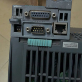
- Check DRIVE-CLiQ Wiring
Confirm that the DRIVE-CLiQ cable is securely connected, the plug is not loose/damaged, and the shielding layer is properly grounded.
Check that the DRIVE-CLiQ address (P0927) of the module is consistent with the CU320 configuration and there is no address conflict.
- Check Firmware Version
Confirm that the firmware version of the PM340 is compatible with the CU320; if the version is too low, upgrade the firmware via STARTER.
- Overload Trip (F0005/F0006)
- Determine Overload Type
Motor Overload: Check r0038 (motor temperature); if it exceeds 150℃, reduce the load or replace the motor with a higher power rating.
Module Overload: Check r0035 (module current); if it exceeds 32A for a long time, check if the load is too heavy, or extend the overload protection time (P217).
- Optimize Parameter Settings
Enable vector control (P1300=20) to improve the motor’s load capacity.
For variable-torque loads (fans/water pumps), enable the energy-saving mode (P1300=2) to reduce module power loss.
III. Troubleshooting Precautions
- Before performing any troubleshooting operations, cut off the input power and control power supply, and wait for the DC bus voltage to drop to 0V (aproximadamente 5 minutos) para evitar choque elétrico.
- After replacing the power module, re-download the parameters and perform motor identification to ensure parameter matching.
- This module is only available as a spare part. If the hardware is damaged and cannot be repaired, prioritize replacing it with a new-generation module of the same power rating, and verify the installation dimensions and interface compatibility.


 Radiation Dosimeter")
 Siemens Servo Motor")
")


NH42-63-318x560.png "Chaves de transferência automática tipo PC CHINT (ATS)NH42-63/4SZ")

")

