 Contactor,întrerupător de circuit,senzor,Codificator,PLC,Convertor

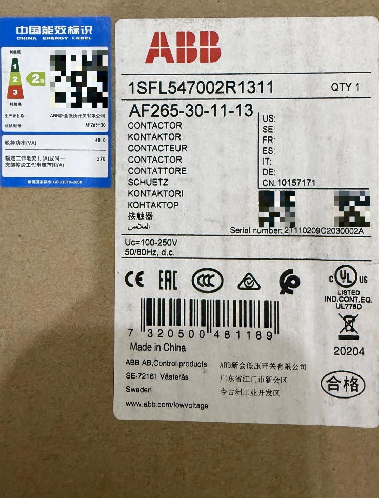

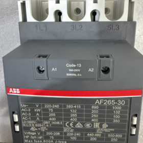
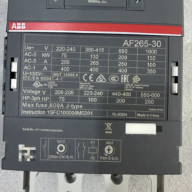
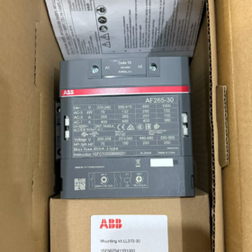
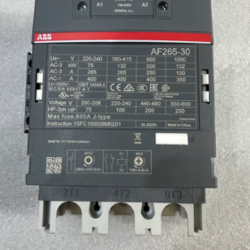
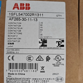
Comanda nr.: 1SFL547002R1311;Material nr.: 10157171
Serie: Seria AF 3-Contactor de stâlp cu bobină electronică universală AC/DC
- Decodarea codului modelului
| Segmentul de model | Descriere |
| DE | Seria AF, bobină electronică universală AC/DC cu gamă largă, suprimarea supratensiunii încorporată; nu este necesară o rețea externă RC sau varistor |
| 265 | Curent nominal de funcționare 265A sub AC-3 @400V; Curent termic convențional (AC-1): 400O |
| 30 | 3-pol, toate contactele principale Normal-deschise (NU); nu principal Normal-Închis (NC) contacte |
| 11 | Contacte auxiliare încorporate: 1NU +1NC |
| -13 | Cod bobină: 100-250V AC/DC (50/60 Hz + Compatibil DC) |
✅ Caracteristici cheie: Bobina simplă suportă AC 100-250V & DC 100-250V; toleranță ridicată la fluctuația tensiunii; consum redus de putere de menținere; functionare silentioasa.
- Specificații electrice de bază
| Articol | Valoare |
| Numărul de poli principali | 3P (3 contacte principale NO) |
| Curentul motorului AC-3 (400 V) | 265 O; Putere motor 132 kW |
| Sarcină rezistivă AC-1 | 400 O |
| Tensiunea nominală de izolație Ui | 1000 V(IEC) /600 V(UL) |
| Tensiune nominală de rezistență la impuls Uimp | 8 kV |
| Tensiunea de control al bobinei | 100‑250V AC/DC 50/60Hz‑DC |
| Contacte auxiliare | 1NU+1NC (montat frontal, nedemontabil) |
| Rezistenta mecanica | 5 milioane de cicluri de operare |
| Frecvența maximă de funcționare | 300 operațiuni/oră |
| Tensiune de preluare | 80 % din tensiunea nominală inferioară a bobinei; Tensiunea de întrerupere 55% din tensiunea nominală mai mică a bobinei |
III. de mediu & Parametri mecanici
| Articol | Valoare |
| Temperatura ambiantă de funcționare (fara releu termic) | -40℃ ~ +70℃; -25℃ ~ +55℃ cu releu de suprasarcină termică |
| Temperatura de depozitare | -40℃ ~ +70℃ |
| Altitudine fără derating | ≤3000m; reducerea nominală necesară peste 3000 m |
| Dimensiuni de gabarit (L×A×D) | 140 mm × 225 mm × 180 mm |
| Greutate netă | 3.9 kg |
| Tip terminal | Circuitul principal: bara colectoare / terminale de tip șurub; Circuit de control: terminale cu șuruburi |
| Metoda de montare | Montare verticală pe șină DIN sau cu șurub pe placa din spate, montarea laterală sau inversată este strict interzisă |
Certificari: CCC, CE, UKCA, EAC, Certificare DNV marine; Siguranta functionala: SIL2, ISO13849-1 Cat.B.
- Principiul de funcționare în profunzime
Contactoarele din seria AF adoptă bobina de tip redresor electronic, diferit de contactoarele AC tradiționale:
- Aplicați 100-250 V AC sau DC la A1/A2; internal electronic circuit rectifies input to DC for driving electromagnetic coil.
- High instantaneous power for pull-in, then switch to low DC holding power; much lower coil heating than conventional AC coils.
- On-board built-in TVS surge absorber dissipates back-EMF upon coil de-energization. Do NOT connect external RC networks or varistors in parallel; external devices may cause malfunction or permanent damage.
- DC-magnetized armature eliminates 50 Hz AC hum noise.
Definiția terminalului
Main circuit line-side: 1L1, 3L2, 5L3; load-side: 2T1, 4T2, 6T3
Bobina: A1, A2 (non-polar for AC & DC)
Contacte auxiliare: 13-14 (NU); 21-22 (NC)
- Lista de ambalare standard & Accesorii optionale
Livrare standard
- AF265-30-11-13 Contactor Unit ×1
- Product manual, certificate of compliance
❗Not included: Releu termic de suprasarcina, mechanical interlock, auxiliary add-on blocks, terminal safety shield.
Separately-ordered Accessories
| Accesorii | Funcţie |
| TA275 DU | Matching thermal overload relay (80‑275 A) |
| CAL19‑11 | Side‑mount auxiliary contact block (1NU+1NC) |
| VM265 | Interblocare mecanică (pentru inversarea taxei) |
| AF-MTP | Capac de protecție a bornei circuitului principal |
- Compatibilitate între mărci & Referință de înlocuire
⚠️Verificați valoarea nominală a bobinei 100-250VAC/DC și AC-3 265A înainte de înlocuire.
| Model original | Echivalent cu potrivire directă | Observații |
| ABB AF265-30-11-13 | A265-30-11 (Legacy EH265) | Bobinele vechi din seria EH sunt numai AC / Doar DC; bobinele nu pot fi schimbate direct |
| Echivalente concurente | Siemens 3RT1066‑6AP36; Schneider LC1D245M7 | Fără bobină nativă AC/DC cu gamă largă de 100-250 V pentru Siemens/Schneider; selectați varianta corectă de bobină |
VII. Scenarii tipice de aplicare
- Ventilator & pompa de pornire a motorului de dimensiuni mari (HVAC, aer conditionat central, tratarea apei)
- Compresor de aer, controlul motorului extruderului (110-132 motoare trifazate kW)
- Comutarea bancilor de condensatoare (se potrivesc cu ratingul AC-1 400A)
- Circuite principale înainte/înapoi și stea-triunghi
- Marin & echipamente orientate spre export: compatibil cu tensiunile globale de control (120 VAC/220VAC universal)
VIII. Capcanele de selecție & Restricții dure
- ❌NU adăugați supresoare de supratensiune externe (Rețele RC, varistoare, diode). Protecție la supratensiune încorporată furnizată; dispozitivele externe cauzează deteriorarea bobinei sau nedeschiderea.
- ❌Montarea laterală sau inversată este interzisă; este permisă numai instalarea verticală.
- ❌Degradarea este obligatorie peste 3000m altitudine; în caz contrar, pot apărea supraîncălzirea prin contact și arderea.
- ❌Nu este potrivit pentru comutarea de înaltă frecvență (>300 operațiuni/oră); utilizați contactori de vid pentru aplicații frecvente.
- ✅Toleranță largă la tensiune de control: tragere fiabilă la 80-250V.
- Depanare
| Simptom | Cauza de bază | Remediu |
| Contactorul nu va intra | Fără tensiune pe A1-A2; conexiuni slăbite; defecțiune a plăcii bobinei electronice interne | Măsurați tensiunea A1-A2; strângeți din nou bornele; înlocuiți unitatea completă (Bobina AF nu poate fi înlocuită separat) |
| Pălăvrăgeală / tragere intermitentă | Tensiune de control sub limita minimă de 80%.; ondulație excesivă a sursei de alimentare | Asigurați-vă că tensiunea de intrare este ≥80V; excludeți capacitatea insuficientă a unității de ieșire a PLC-ului |
| Încălzire excesivă a terminalului circuitului principal | Cuplul șuruburilor insuficient; suprasarcina; eroziunea de contact / ardere | Strângeți șuruburile barelor colectoare; verifica curentul de sarcina; înlocuiți contactorul pentru ablația de contact severă |
| Contactele rămân închise după deconectare (lipirea) | Sudarea contactului principal; tensiune reziduală indusă pe cablajul de comandă | Investigați condițiile de scurtcircuit pe partea de sarcină; eliminați tensiunea reziduală indusă în cablurile de comandă |
Important: Placa electronică a bobinei din seria AF este integrată în interiorul unității; Defecțiunile bobinei necesită înlocuirea completă a contactorului; nu sunt disponibile ansambluri de bobine de rezervă.
ABB AF265-30-11-13 Instrucțiuni de utilizare (Manual compilat)
Documentul manual original corespunzător nr.: 1SFC100008M0201, dimensiunea cadrului aplicabilă: seria AF190-205-265-305-370
Comanda nr.: 1SFL547002R1311;Evaluarea bobinei: 100-250 V AC/DC
⚠️Avertisment de siguranță: Instalarea și punerea în funcțiune trebuie efectuate de personal electric calificat. Deconectați toată sursa de alimentare din amonte înainte de orice cablare sau lucrări de întreținere. NU aplicați testul dielectric de înaltă tensiune la bornele bobinei A1/A2; placa cu bobina electronică va suferi daune permanente de defecțiune.
Cuprins
- Prezentare generală a produsului
- Model & Definiția terminalului
- Specificații de instalare
- Cablaj & Cuplul de strângere
- Instrucțiuni de operare a bobinei (AF Electronic Coil Key Notes)
- Procedura de punere în funcțiune
- Montarea accesoriilor
- Program de întreținere & Articole de inspecție
- Depanarea erorilor
- Operațiuni interzise
- Acces la manualul original PDF
- Prezentare generală a produsului
AF265-30-11-13 este un contactor cu 3 poli cu bobină electronică cu gamă largă integrată și supresie de supratensiune încorporată. RC extern / supresoarele cu varistor sunt interzise.
AC-3-400V: 265 O, putere motor 132 kW
AC-1 rezistiv: 400 O
Contacte auxiliare încorporate:1NU(13-14)+1NC(21-22)
Evaluarea bobinei:100-250 V AC/DC; tragere ≥80%Uc; abandon ≤55%Uc
Rezistenta mecanica:5 milioane de cicluri; frecventa maxima de functionare 300 operațiuni/oră
Temperatura de functionare:-40 ℃~+70℃ (fara releu termic); fără derating ≤3000m altitudine.
- Definiția terminalului
| Circuit | Terminalul nr. | Descriere |
| Circuitul principal pe partea de linie | 1L1, 3L2, 5L3 | 3intrare de putere de fază |
| Circuitul principal pe partea de sarcină | 2T1, 4T2, 6T3 | Motor / conexiune de sarcină |
| Bobina | A1, A2 | Nepolar pentru AC/DC; nominal pentru 100-250 V AC/DC |
| Auxiliar încorporat NR | 13-14 | În mod normal, deschis |
| NC auxiliar încorporat | 21-22 | În mod normal, închis |
Blocul suplimentar CAL19-11 poate fi montat pe partea stângă a unității.
- Specificații de instalare
- Orientarea montajului: numai instalarea verticală (bornele principale verticale sus-jos). Montarea laterală sau inversată este strict interzisă.
- Două opțiuni de instalare:
Fixare cu șuruburi pe placa din spate: 4 buc șuruburi M8
Montare pe șină DIN35mm (Pentru AF265 cu cadru mare, montarea cu șurub este preferată în locul montajului pe șină).
- Disiparea căldurii din dulap: Mai multe unități pot fi montate una lângă alta, fără goluri; fără derating până la 70℃ ambiental. Reducerea este obligatorie pentru altitudine >3000 m.
- Dimensiunea minimă recomandată a dulapului: ≥900×750×300mm, pentru a asigura o ventilație adecvată sus-jos.
- Preveniți așchiile de metal și praful de găurit să intre în carcasa contactorului în timpul instalării.
- Cablaj & Cuplul de strângere (Majoritatea supraîncălzirii provine din un cuplu insuficient)
| Locația terminalului | Dimensiunea șurubului | Cuplul de strângere recomandat | Cerințe de cablu |
| Borne L/T ale circuitului principal | M12 | 24 N·m | Bară de cupru / Urechi ATK300; 75 Conductori de cupru evaluați ℃; Conectarea directă a conductorului de aluminiu este interzisă |
| Bobina A1-A2 | M4 | 1.2-1,5 N·m | 0.75Sârmă de cupru de 2,5 mm² |
| Contacte auxiliare | M4 | 1.2 N·m | 0.75Sârmă de cupru de 2,5 mm² |
Pentru circuitul principal sunt recomandate urechi sertizate ATK300. Montați ecranul de siguranță pentru terminalul AF-MTP peste conductorii sub tensiune pentru protecție împotriva atingerii.
- Instrucțiuni de operare a bobinei (AF Electronic Coil Key Notes)
- Terminalele bobinei A1/A2 sunt nepolare; fie AC sau DC 100-250V pot fi aplicate direct.
- Suprimarea supratensiunii TVS încorporată la bord. Amortizor RC extern, varistorul sau dioda cu roată liberă sunt strict interzise. Dispozitivele externe de supratensiune vor arde placa bobinei sau vor cauza defecțiunea la deschidere.
- Tragere: închidere fiabilă ≥80% ×100V = 80V.
- Renunța: deschidere fiabilă ≤55%Uc.
- Consum redus de energie de reținere; functionare silentioasa, fara zumzet.
- ❗Placa electronică a bobinei este integrată în unitatea principală. Bobina nu poate fi înlocuită separat; este necesară înlocuirea completă a unității la defectarea bobinei.
- Test de rezistență dielectrică: Nu efectuați niciodată testul de hipot între bornele bobinei A1-A2; va distruge circuitul electronic.
- Etape de punere în funcțiune
- Toată puterea deconectată; verificați cablarea completă și valorile cuplului; confirmați că capacul camerei arcului este complet așezat și intact.
- Confirmați potrivirile tensiunii de alimentare de control -13 evaluarea bobinei (100-250 VAC/DC).
- Mențineți alimentarea principală trifazată deconectată; alimentați numai circuitul de comandă pentru testul funcțional fără sarcină:
Aplicați tensiune la A1-A2: contactorul trebuie să intre imediat; dezactivați pentru eliberare imediată, fără zgomot.
Verificați logica contactelor auxiliare: 13-14 deschide/închide, 21-22 închide/deschide conform așteptărilor.
- Continuați să alimentați alimentarea principală numai după testul fără sarcină reușit, efectuați o operațiune de probă încărcată.
- Rulați sub sarcină maximă minim 30 de minute; Măsurați creșterea temperaturii terminale; creștere acceptabilă a temperaturii carcasei ≤60K.
- Montarea accesoriilor
- CAL19-11 (bloc auxiliar montat lateral): Glisați în fanta din partea stângă a contactorului până când este blocat complet; adaugă contacte 1NO+1NC.
- Interblocare mecanică VM265: pentru aplicarea interblocării înainte-înapoi; sunt necesari doi contactori ca pereche.
- TA275-DU releu termic de suprasarcina: instalare de jos; intervalul de temperatură de funcționare a releului -25~+55℃.
- Scut de siguranță pentru terminalul circuitului principal AF-MTP, previne atingerea accidentală a barelor sub tensiune.
Toate accesoriile sunt comandate separat, nu este inclus ca livrare standard.
- Întreținere periodică & Inspecţie
Perform only with full power disconnected! Interval de întreținere: every 12 months for clean environment; every 6 months for dusty / high-vibration conditions.
- Retighten all main-circuit terminals to specified torque.
- Inspect arc-chamber cover for cracks, carbon deposits or metal powder accumulation; replace arc-chamber for severe burning.
- Inspect main contact erosion; replace complete unit for heavy wear or contact welding. No separate contact spare-parts available for AF265.
- Clean external dust. Do NOT blow compressed-air directly into enclosure, metal dust may damage internal coil electronics.
- Verify cabinet ambient temperature and unobstructed ventilation paths.
- Functional test of auxiliary contact switching.
Nota: AF190-AF370 frame units have no serviceable separate contact assemblies; full-unit replacement required upon contact damage.
- Troubleshooting Table
| Simptom | Cauza | Remediu |
| Contactorul nu va intra | Fără tensiune A1-A2; conexiuni slăbite; defecțiune a bobinei electronice interne | Măsurați tensiunea A1-A2; strângeți din nou bornele; înlocuiți unitatea completă |
| Pălăvrăgeală / sărituri repetate | Tensiune de control sub 80% minim; unitate de ieșire PLC insuficientă; tensiune reziduală indusă în cablajul de comandă | Verificați tensiunea de alimentare; îmbunătățiți capacitatea unității PLC; eliminarea tensiunii reziduale induse |
| Nu se va deschide după deconectare (lipirea) | Sudarea contactului principal; tensiune reziduală indusă pe circuitul de comandă; componente de supratensiune externe incomplet eliminate | Localizați defecțiunea de scurtcircuit pe partea de sarcină; eliminarea tensiunii induse; îndepărtați complet RC extern / dispozitive cu varistor |
| Încălzire excesivă la bornele principale | Cuplul șuruburilor insuficient; cablu subdimensionat / bara colectoare; starea de suprasarcina | Restrângeți elementele de fixare; recalculați ampabilitatea conductorului; măsura curentul de sarcină real |
| Bobina arde imediat după alimentare | Testul Hipot aplicat la A1-A2; dispozitive externe de supratensiune; tensiunea de alimentare depășește limita superioară de 250 V | Interziceți hipot pe bornele bobinei; îndepărtați componentele externe de supratensiune; limitează tensiunea de control în intervalul nominal de 100-250V |
- Operațiuni interzise
❌Montarea laterală sau inversată este interzisă;
❌ Ipot / Testul megger pe bornele bobinei A1/A2 este interzis;
❌Snubber RC extern, varistorul sau dioda de rulare liberă sunt interzise;
❌Nu depășiți 300 operațiuni/frecvență de comutare oră;
❌Funcționare fără derating pentru altitudine >3000 m interzis;
❌Nu încercați să dezasamblați ansamblul electronic al bobinei interne; fără piese de schimb reparabile.
- Acces la manualul original PDF
- Vizitați pagina oficială a produsului ABB, căutare numărul de comandă 1SFL547002R1311 → secțiunea Descărcări, descărcați fișa de date și instrucțiuni de operare.
- Numerele de referință ale documentelor: Instructiuni de operare: 1SFC100008M0201 (multilingv inclusiv chineza); Manual de service 1SFC101044M0201.







NH42-63-318x560.png "Comutatoare de transfer automat de tip PC CHINT (ATS)NH42-63/4SZ")



