 Contactor,întrerupător de circuit,senzor,Codificator,PLC,Convertor

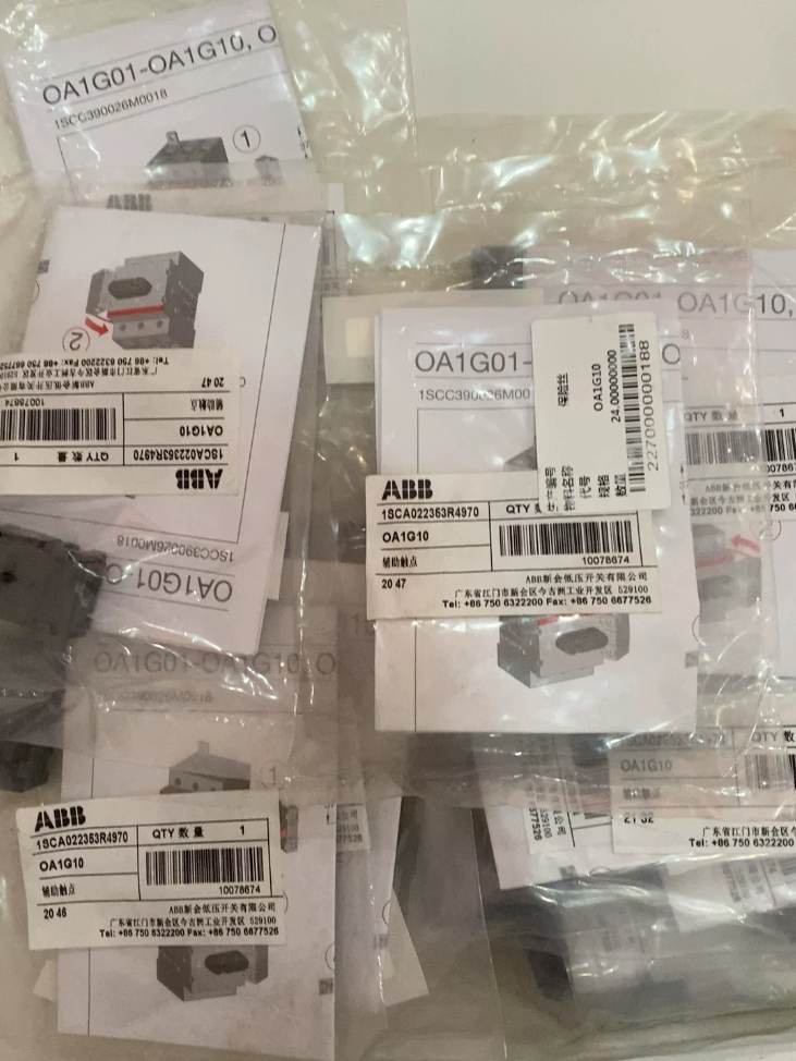

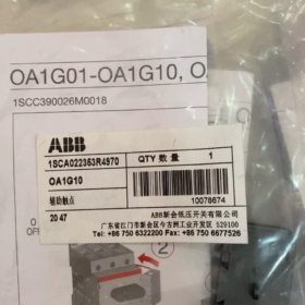
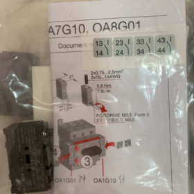
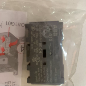
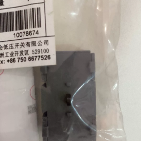
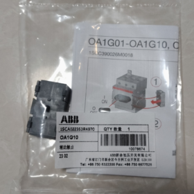
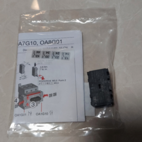
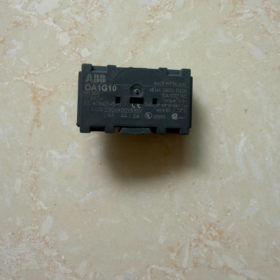
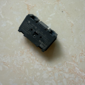
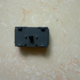
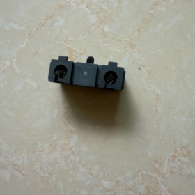
Numele complet: ABB OA1G10 1NO Auxiliary Contact
Partea nr.: 1SCA022353R4970. Designed for right-hand mounting on ABB OT series disconnectors / load break switches. 1 Deschis normal (1NU), early-make contact.
✅ Model Interpretation
OA: Contact auxiliar modul
1: 1 contact set
G: Right-side mounting
10: NO Normally Open contact (OA1G01 = 1NC Normally Closed)
📋 Core Technical Data
| Articol | Caietul de sarcini |
| Formular de contact | 1NU, one normally open set |
| Rated thermal current Ith | 16O |
| Tensiunea nominală de izolație Ui | 690V |
| Impulse withstand voltage Uimp | 4kV |
| Categoria de utilizare | AC-15 |
| Curent de funcționare | AC230V:6O; AC400V:4O; AC690V:2O |
| Specificația cablajului | 0.75~2,5 mm², M3.5 screw, torque 0.8Nm |
| Clasa de protectie | IP20 |
| Dimensiunea de ansamblu | W11mm × H37mm × D21mm; Net weight approx.15g |
| Standarde | GB/T 14048.5, IEC 60947-5-1 |
🛠️ Compatible Switch Models
Suitable for ABB OT series load disconnectors: OT16 ~ OT4000, OTP, OTR, OTL, OTE
Installation note: Right-side mounting, maxim 2 OA1G series auxiliary contacts can be fitted. Used to collect ON/OFF status signals of disconnectors for PLC, indicator lights and interlock circuits.
📌 Application Scenarios
Disconnector position feedback in power distribution cabinets, MCC, Cutii combinatoare fotovoltaice, HVAC pump control cabinets
Safety interlock, interblocarea ușii dulapului, status indicator lamps, switch position acquisition for host system
Main power disconnector signal feedback for machinery
🧩 Series Comparison & Alternative
- OA1G01: 1NC (În mod normal închis, right mounting)
- OA7G10: 1NU (Deschis normal, left mounting)
- OA8G01: 1NC (În mod normal închis, left mounting)
OA1G10AU: delayed version, do not confuse with standard model.
📦 Foreign Trade Information
Cod HS: 85389099 (Electrical equipment parts), Origine: Bulgaria / Finlanda
ABB OA1G10 Auxiliary Contact Installation Manual (Compiled from ABB original document Doc.No.:1SCC390026M0018)
Produs: OA1G10 1NO auxiliary contact, snap-fit right-side mounting for OT series disconnectors, early-make contact; Partea nr.:1SCA022353R4970
Compatible units: OT16~OT4000, OTP/OTR/OTL/OTE load disconnectors; related series: OA1G01 (right 1NC), OA7G10 (left 1NO), OA8G01 (left 1NC)
- Avertismente de siguranță
- Installation must be performed by qualified electricians. Disconnect main power supply of the disconnector and verify zero voltage before work to prevent electric shock and arc burns.
- Never plug or remove auxiliary contact module under energized condition.
- Auxiliary contacts are only intended for control / signal circuits (AC-15), not for main power load.
- După instalare, manually operate the disconnector several times to verify contact operation logic.
- Prezentare generală a produsului
Evaluarea contactului: 1NU (one normally open set), early-make (auxiliary contact closes in advance before main contacts of disconnector close)
Rated thermal current: Ith=16A; AC230V 6A / AC400V 4A / AC690V 2A
Metoda de montare: snap-fit, right side of disconnector. Max. 2 OA1G auxiliary contacts can be mounted side by side on one disconnector.
Terminal: M3.5 screw, recommended torque 0.8 Nm (7 lb.in)
Cablu: 0.75~2.5 mm² copper conductor, stripping length 8~10 mm
III. Etape de instalare
Precondition: Disconnector set to OFF position (0)
- Locate mounting slot
Find the auxiliary contact guide rail on the right side of OT disconnector body. Left rail is only for OA7G/OA8G series, OA1G10 cannot be fitted on left side.
- Snap module into place
Align guiding catches of OA1G10 with right rail, press evenly inward until a clear “clic” se aude sunet, confirming locking. Pull module slightly to confirm secure fixation.
Multiple modules: până la 2 unitati, snap in sequentially side by side on right rail.
- Wire signal circuit
Strip insulation of control wire by 8–10mm, insert into terminal; tighten M3.5 screw to torque 0.8Nm.
Marcaj terminal: 1 şi 2 are two terminals of NO contact.
Nota: Do not use conductors larger than 2.5mm², poor terminal compression will occur.
- Function verification
Manually operate disconnector handle:
ON position (eu): OA1G10 NO contact closes; early-make feature: auxiliary contact conducts before main contacts close
OFF position (0): OA1G10 NO contact opens
Use multimeter continuity test on terminals to confirm correct logic.
- Secondary protection check
Ensure wires are not pinched, no bare copper exposed on terminals; fit terminal cover of cabinet.
- Removal Procedure
- Cut off power of secondary signal circuit.
- Set disconnector to OFF position 0.
- Use small flat screwdriver to pry side catch of module, pull OA1G10 outward.
- Loosen terminal screws and remove control wires.
- Installation Limitations & Reguli de selecție
- OA1G10 = Right mounting. Left-side status feedback requires OA7G10.
- For one OT switch: max. 2 OA1G on right rail; max. 2 OA7G/OA8G on left rail.
- No cross mixing: OA1G (right type) cannot be inserted into left rail. Mismatched mechanical structure may damage module and switch body by force.
- OA1G10AU is delayed-travel version with different mechanical stroke; cannot directly replace standard OA1G10.
- Punerea în funcțiune & Depanare
| Simptom | Cauza de bază | Remediu |
| Auxiliary contact does not conduct when switch ON | Module not fully snapped; module fitted on left rail; contact plunger stuck | Power off and re-install; confirm right-side mounting; check foreign object jamming |
| Intermittent signal | Cuplu de strângere insuficient; oversized wire; oxidized terminals | Retighten to 0.8Nm; replace wire ≤2.5mm²; clean terminals |
| Opposite contact logic | OA1G01 (NC) mistakenly used instead of OA1G10 | Check part number and replace with OA1G10 |
| Module cannot be snapped in | Slot is left rail; module catch deformed | Use OA7G10; replace damaged module |
VII. Întreţinere & Depozitare
- Periodic inspection: Manually operate switch every 6 luni, check contact operation and wiring tightness.
- Storage environment: Clean and dry, temperature -25℃~+70℃, avoid condensation and dust.
- Durata de viata mecanica: Matched with OT disconnector, tipic 20000 cicluri de operare.
VIII. Original Document Reference
Original manual title: Installation Instruction Auxiliary contact OA1G01-OA1G10, OA7G10, OA8G01
ABB Document No.: 1SCC390026M0018
Standarde aplicabile: GB/T 14048.5, IEC 60947-5-1
⚠️ Troubleshooting Summary
- Contact failure: Verify full installation and handle travel; loose module catch is common fault.
- Semnal instabil: Check screw torque, wire size ≤2.5mm²; AC15 category, heavy load not allowed.
- Selection reminder: OA1G10 is right-mounted only. OA7G10 for left-side feedback.
Key Installation Notes for ABB OA1G10 Auxiliary Contact
OA1G10: Right-mounted, 1NO early-make auxiliary contact for OT disconnectors, Part No.1SCA022353R4970
- Pre-installation Check Items
- Mounting side must be correct
OA1G10 only fits right guide rail of OT switch. Left rail only accepts OA7G10/OA8G01. Forced fitting on left side causes unlocked catch, failed plunger actuation or permanent damage.
- Switch status confirmation
Instala / remove only with OT disconnector at OFF position 0, main circuit and secondary signal circuit de-energized and verified. Hot plugging of auxiliary module is forbidden.
- Check model timing characteristic
OA1G10 is early-make contact: auxiliary contact closes before disconnector main contacts. If interlock logic requires signal output only after main contact closure, this model is not suitable.
- Quantity limit
Max. 2 OA1G modules (OA1G10 / OA1G01) can be stacked on right rail of one OT switch.
- Mechanical Installation Details
- Snap-fit feedback
Align module guiding ribs with right rail, press steadily inward until distinct “clic” for locking. Pull module lightly after fitting to confirm no loosening.
Stack multiple modules: insert sequentially, keep modules closely fitted without gap.
- Plunger inspection
După instalare, inspect black actuating plunger of module. Plunger extends when switch OFF; plunger is pressed in during switch ON to trigger contact switching. Plunger shall not be skewed or stuck.
- No hammering allowed
Do not strike module with screwdriver or hammer if insertion is difficult. Plastic housing or internal contact spring may break.
III. Secondary Wiring Details
- Cable requirement
Copper wire 0.75~2.5mm²; stripping length 8~10mm. Overlong stripped insulation may cause short circuit between adjacent terminals; insufficient stripping leads to poor crimp.
- Cuplul de strângere
M3.5 terminal screw, standard torque 0.8 Nm. Low torque → intermittent signal under vibration; excessive torque → thread slipping and terminal base damage.
- Terminal definition
Terminale 1 şi 2 form NO contact, non-polarized passive dry contact. Not for high power load, utilization category AC-15.
Rating reference: AC230V 6A, AC400V 4A, AC690V 2A, for PLC, indicator lamps and interlock control circuits only.
- Punerea în funcțiune & Verificare (Critic)
- Multiple manual operation test
După instalare, toggle OT switch ON/OFF for at least 3~5 cycles. Measure with multimeter continuity function:
OFF position 0: Terminal 1-2 deschide
ON position I: Terminal 1-2 închis (early-make: conduction occurs before handle fully reaches ON position)
- Fault discrimination
No contact switching: mostly incomplete snap-fit, wrong mounting side;
Intermittent conduction: insufficient screw torque, loose copper strands;
Reversed logic: OA1G01 (NC) mistakenly selected.
- Operațiunea & Maintenance Restrictions
- Auxiliary contact cannot be used as main circuit switch, only for position feedback and safety interlock signal.
- For cabinets under heavy vibration, recheck screw torque and catch condition every 6 luni.
- Mediu: Keep away from dust, condensation and corrosive gas to prevent contact oxidation and signal drift.
- Îndepărtarea: Opriți mai întâi, pry side catch gently with flat screwdriver and pull out module. Never pull module by wires.
- Neînțelegeri comune
❌ Neînțelegere 1: OA1G10 can be mounted on either side → Not interchangeable, plunger geometry differs
❌ Neînțelegere 2: Auxiliary contact can drive heavy loads such as contactor coils → AC15 duty, limited load capacity
❌ Neînțelegere 3: Conduction occurs only when handle fully ON → Early-make design, conducts in advance, timing must be considered for interlock design
❌ Neînțelegere 4: Unlimited stacking of auxiliary contacts → Max. 2 units on right rail







NH42-63-318x560.png "Comutatoare de transfer automat de tip PC CHINT (ATS)NH42-63/4SZ")



