 Contactor,întrerupător de circuit,senzor,Codificator,PLC,Convertor


Informații de bază
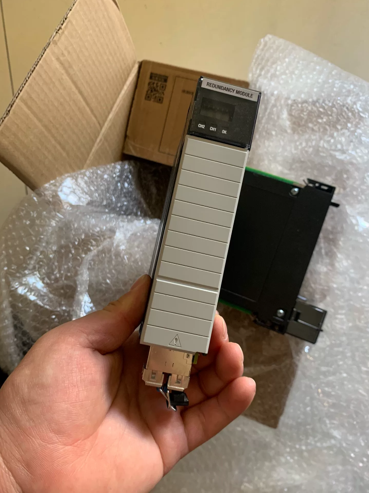
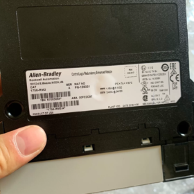
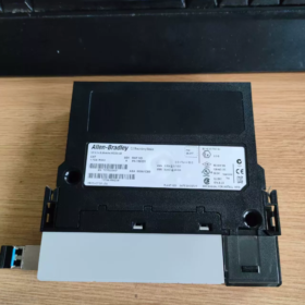
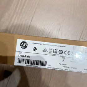
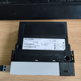
Numele complet: 1756‑RM2 ControlLogix Enhanced Redundancy Module
Marca: Allen-Bradley (Rockwell Automation)
Platformă: ControlLogix 1756 Seria șasiu
Poziționare: Modul de sincronizare a redundanței controlerului îmbunătățit pentru construirea sistemelor de redundanță la nivel de controler la nivel de controler ControlLogix
Ciclu de viață: Matură activă (faza de maturitate, aprovizionare normală, deservibil)
Funcția de bază
Trebuie folosit în perechi (1 modul în șasiu primar + 1 modul în șasiu secundar), realizând următoarele prin legătură cu fibră optică:
- Sincronizare de mare viteză în timp real a programelor de control primar/secundar, etichete, stări de sarcină, și date I/O
- Monitorizarea stării de sănătate operaționale a controlorului primar
- Comutare automată fără lovituri la declanșarea defecțiunii (timpul tipic de comutare < 100 Domnișoară)
⚠️ Nu poate funcționa ca un singur modul; nu trebuie amestecat cu 1756-RM mai vechi — ambele șasiuri trebuie să utilizeze RM2.
Specificații tehnice cheie
| Parametru | Caietul de sarcini |
| Puterea backplane | 1.16 A @ 5.1 În DC; 3.4 mA @ 24 În DC |
| Consum maxim de energie | 6 W |
| Lățimea de bandă de sincronizare | 1 Gbps (Legătură de fibră Gigabit) |
| Interfață cu fibră | Canale duble SFP fibră (Canalul A/B, redundanță legături) |
| Cabluri de fibră compatibile | 1756‑RMC1 (1 m), 1756‑RMC3 (3 m), 1756‑RMC10 (10 m) |
| Temperatura de operare standard | -20 °C ~ +70 °C |
| Greutate | ≈ 0.3 kg |
| Certificare de siguranță | Suportă scenarii de aplicație SIL2 |
Variante de model
- 1756‑RM2 (Standard): Pentru utilizare în interior în dulapuri de control convenționale
- 1756‑RM2XT (Temperatură extinsă): -40 °C ~ +70 °C, pentru dulapuri exterioare/neaer condiționat; trebuie utilizat cu șasiul din seria XT
Regula de împerechere: RM2 ↔ RM2; RM2XT ↔ RM2XT; amestecarea încrucișată nu este permisă
Lista de controlere compatibile
Acceptă numai ControlLogix 5560 / 5570 serie:
1756-L71, L72, L73, L74, L75
1756-L61, L62, L63
Se aplică cerințele minime privind versiunea de firmware; consultați manualul oficial de redundanță. 5580 (L8x) nu folosește 1756‑RM2; utilizați în schimb 1756‑RM3.
1756‑RM2 vs. Legacy 1756‑RM
| Articol | 1756‑RM2 (Redundanță îmbunătățită) | 1756‑RM (Redundanță tradițională) |
| Viteza de sincronizare | 1000 Mbps | 100 Mbps |
| Capacitate de sincronizare a datelor | Suporta volume mai mari de etichete, cicluri de scanare mai rapide | Se luptă cu sincronizarea volumului mare de date |
| Legătură de fibră | Fibră dublă redundantă | Legătură unică |
| Amestecarea | Nu poate fi asociat cu RM | Nu poate fi asociat cu RM2 |
| Recomandat pentru proiecte noi | ✅ De preferat | ❌ Numai întreținerea sistemului vechi |
Configurație de redundanță minimă – Arhitectură hardware
2 × 1756‑RM2
2 controlere redundante de același model și firmware
2 seturi de 1756 şasiu, 2 surse de alimentare
Toate modulele de comunicație din șasiul primar și secundar trebuie să fie asociate unu-la-unu (acelasi model, același firmware)
O pereche de cabluri de fibră 1756‑RMCxx care conectează cele două module RM2
Specificații obligatorii de instalare
- Ambele module RM2 trebuie instalate exact în același număr de slot în ambele șasiu;
- Legătura de fibră conectează direct cele două module RM2 - fără comutatoare între ele;
- Toate modelele de module și versiunile de firmware atât în șasiu primar, cât și în cel secundar trebuie să fie strict identice;
- Raza minimă de îndoire a fibrei ≥ 30 mm; porturile SFP neutilizate trebuie să fie prevăzute cu capace de protecție.
Configurare software
Software de programare: Studio 5000 Logix Designer
Instrument însoțitor: RMCT (Instrument de configurare a modulului de redundanță)
Mod redundanță: Redundanță îmbunătățită
Industrii de aplicare tipice
Termo/hidroenergetic, petrochimic, tratarea apei, tranzit feroviar, linii de producție la scară largă, Control DCS — procese continue care nu pot tolera timpul de nefuncționare.
Definiții indicator LED (Panoul frontal al modulului)
Bine: Alimentarea modulului și backplane sunt normale
CHA / CHB: Starea celor două legături de fibră optică
SINCRONIZARE: Starea de sincronizare primară/secundară
Puncte comune de depanare
- LED-ul SYNC este stins: Rupere de fibre, conectori murdari, modele de module nepotrivite la ambele capete, poziții inconsecvente ale sloturilor;
- Comutări frecvente: Versiuni de firmware inconsistente, putere insuficientă pentru backplane, atenuarea excesivă a fibrelor;
- Nu se poate intra în starea de calificare: Module incompatibile prezente în șasiu.
1756-RM3 Relație de înlocuire completă & Note de compatibilitate (vs. 1756-RM2, Concentrați-vă pe controlerele L8)
- Core Hard Compatibility Liniile roșii (Reguli oficial obligatorii)
Împerecherea între modele NU este permisă!
- 1756-RM2 / RM2XT
✅ Suportă: 5570 (L7x) controlorii
❌ Nerecomandat oficial pentru proiecte noi cu L8x (5580); L8+RM2 existent este o soluție de compatibilitate tranzitorie și nu primește suport pentru funcții noi
❌ Absolut nu se poate asocia cu RM3 (un RM2 + un RM3 nu poate stabili sincronizarea prin redundanță)
- 1756-RM3 / 1756-RM3XT (Model de temperatură extinsă)
✅ Suport nativ: 5580 (L8xEP), 5570 (L7x), 5590 controlere de ultimă generație
✅ Modul standard desemnat oficial pentru sistemele de redundanță din seria L8
❌ Nu poate fi asociat cu RM2/RM2XT
Regula de fier de asociere:
RM2 ↔ RM2; RM2XT ↔ RM2XT
RM3 ↔ RM3; RM3XT ↔ RM3XT
Împerecherea încrucișată este strict interzisă
- Foaia de parcurs pentru înlocuirea generațiilor
Cale 1: Noua selecție de proiecte (Preferat)
L7x (5570) proiecte noi: Alegeți fie 1756-RM2, fie 1756-RM3
L8x (5580) proiecte noi: Selecția obligatorie de 1756-RM3; RM2 nu mai este recomandat
Strategia de produs Rockwell pe termen lung: RM3 este înlocuitorul de upgrade de generație următoare pentru RM2; noile funcții viitoare vor fi repetate numai pe RM3
Cale 2: Migrare existentă de actualizare a sistemului
Scenariul A: L7x existent + 1756-Sistemul RM2
Nu se poate efectua direct upgrade online de înlocuire a unui singur modul
Alegeți una dintre cele două opțiuni:
- Opriți și înlocuiți ambele module RM2 → înlocuiți ca o pereche cu 1756-RM3; șasiul și procesorul pot rămâne L7x; re-descărcați configurația de redundanță
- Continuați să rulați cu RM2, procurați doar RM2 ca piese de schimb (nota: faza de maturitate a ciclului de viață)
Scenariul B: Migrare upgrade controler de la L7x la L8x
⚠️ Important: Controlerele L8 nu pot transfera direct modulele RM2 existente (risc ingineresc ridicat)
Soluție standard de migrare:
L7 + RM2 → Modernizare completă a sistemului: Înlocuiți controlerul cu L8x + înlocuiți modulele de redundanță ca pereche cu 1756-RM3
III. Diferențele cheie: 1756-RM3 vs. 1756-RM2 (Baza de selecție)
| Element de comparație | 1756-RM2 | 1756-RM3 |
| Interfață cu fibră | Modul optic integrat fix, Este necesar un cablu dedicat 1756-RMCxx | Modul SFP interschimbabil la cald (Interfață LC), selecție flexibilă a SFP multimod/monomod |
| Distanța maximă de fibre | Cablu de fabrica max 10 m | Până la 70 km cu SFP de lungă durată, potrivit pentru șasiuri separate pe distanțe lungi |
| CPU compatibil | L6x, L7x; Compatibil L8 (tranzitorie) | Compatibilitate deplină cu L7x, L8x (5580), 5590; optimizare nativă pentru L8 |
| Capacitate de diagnosticare | Alarme de bază | Înregistrare încorporată în jurnalul defecțiunilor cardului microSD, diagnosticare rafinată a legăturilor, monitorizarea puterii prin fibră optică |
| Lățimea de bandă de sincronizare prin redundanță | 1 Gbps | 1 Gbps, optimizat pentru eficiența sincronizării cu etichete mari L8 |
| Versiune minimă de software | Studio 5000 V28+ | Studio 5000 V33.00 și mai sus |
| Versiune XT cu temperatură extinsă | 1756-RM2XT | 1756-RM3XT (-25 ~ +70 °C) |
| Cablu Fibră | Trebuie să achiziționați 1756-RMC1/RMC3/RMC10 dedicat | Nu este necesar un cablu dedicat; fibră LC standard + potrivire SFP |
- Lista de configurare obligatorie pentru L8 (5580) Sistemul de redundanță al controlerului (folosind RM3)
- Pereche: 2 × 1756-RM3 (sau RM3XT asociat)
- CPU: Același model L8xxEP / L8xxEPXT (primar și secundar complet identic)
- Şasiu: Același model pentru primar și secundar; RM3 instalat exact în același număr de slot
- Module de comunicare: Modulele din ambele șasiu împerecheate unu-la-unu, versiuni de firmware unificate
- module SFP: Ambele module RM3 trebuie să utilizeze același model SFP; conexiune directă prin fibră, nu este permis niciun releu de comutare
- Software: Studio 5000 ≥ V33
- Clarificarea concepțiilor greșite comune ale ingineriei
- ❌ Concepție greșită: “Am un controler L8 existent, Cumpărați doar 2 RM și va funcționa”
✅ Fapt: Poate rula la nivel hardware, dar este o soluție de compatibilitate tranzitorie; noile funcții de diagnosticare RM3 și fibră pe distanțe lungi nu sunt disponibile; nerecomandat oficial pentru proiecte noi; există riscuri de compatibilitate cu viitoarele actualizări de firmware.
- ❌ Concepție greșită: Un RM2 și unul RM3 pot forma o pereche pentru redundanță
✅ Fapt: Nu se poate sincroniza complet; sistemul nu poate intra în starea Calificare pregătită; nu încerca
- ❌ Concepție greșită: RM3 poate folosi direct cablurile de fibră RM2 existente 1756-RMC
✅ Fapt: Interfața este incompatibilă! RM3 utilizează interfața standard SFP LC și nu poate folosi cabluri din seria RMC dedicate RM2.
- Recomandări de achiziție de piese de schimb
- Noi proiecte de redundanță L8: Achiziționați direct 1756-RM3 (alegeți RM3XT pentru medii cu temperatură extinsă)
- L7 existent + sisteme RM2: Continuați să achiziționați RM2 ca piese de schimb; planificați o actualizare asociată unică la RM3 în timpul planificării modernizarii
- Planificare pe termen lung: Prioritizează RM3 pentru toate sistemele noi de redundanță; RM2 s-a poziționat treptat ca piese de schimb vechi de întreținere
Allen‑Bradley 1756‑RM3 Specificații tehnice detaliate complete
Informații de bază
Model: 1756-RM3 (Standard) / 1756-RM3XT (Ediția Extended Temperature XT)
Numele complet: Modul de redundanță ControlLogix Premium
Platformă: ControlLogix 1756 Şasiu
Poziționare: Modul de redundanță standard oficial pentru 5580 (L8xEP) controlorii; compatibil cu L7x (5570) controlorii
Regula obligatorie de împerechere: Folosit in perechi; RM3 ↔ RM3; RM3XT ↔ RM3XT; este strict interzisă combinarea cu RM2/RM2XT
- Parametrii electrici (Puterea backplane)
| Parametru | 1756-RM3 / 1756-RM3XT |
| 5.1 V DC Curent de fundal | 1.18 O |
| 24 V DC Curent de fundal | 3.4 mA |
| Consum maxim de energie | ≈ 6.2 W |
| Slot pentru modul | Modul cu un singur slot, ocupa 1 slot in 1756 şasiu |
| Hot Swap | Suportă schimbarea la cald a șasiului (nu se recomandă îndepărtarea individuală în timpul operațiunii de redundanță) |
- Interfață de comunicare prin fibră (Diferența cheie față de RM2)
- Canale: Sloturi SFP duale independente (Link1 / Link2, redundanță legături)
- Tip de interfață: Standard industrial SFP, Interfață fibră LC duplex
❗ Nu se pot utiliza cabluri dedicate RM2 din seria 1756‑RMCxx
- Viteza de sincronizare: 1000 Mbps (Gigabit)
- SFP acceptat (Compatibil oficial)
SFP multimod: Distanta scurta (≤ 2 km), 850 nm
SFP LX monomod: 1310 nm, până la 10 km
SFP monomod cu acoperire lungă: Până la 70 km (potrivit pentru scenarii de separare a șasiului primar/secundar pe distanțe lungi)
- Topologie Cerință obligatorie: Două module RM3 conectate direct prin fibră; fibra nu trebuie să treacă prin comutatoare sau transceiver-uri optice ca intermediari
- Raza de curbură minimă a fibrei: ≥ 30 mm
III. Lista de controlere compatibile
✅ Suport complet nativ
1756-L81EP, L83EP, L85EP (5580 controlere standard)
1756-L81EPXT, L83EPXT, L85EPXT (Controlere de temperatură extinse XT)
1756-L71/L72/L73/L74/L75 (5570 Seria L7)
✅ Compatibil cu controlerele de siguranță GuardLogix L8x
❌ Nu acceptă controlere vechi L6x; nu acceptă asocierea cu RM2 pentru redundanță
- Specificații de mediu
| Parametru | 1756-RM3 (Standard) | 1756-RM3XT (Temperatură extinsă) |
| Temperatura de operare | 0 °C ~ +60 °C | -25 °C ~ +70 °C |
| Temperatura de depozitare/transport | -40 °C ~ +85 °C | -40 °C ~ +85 °C |
| Umiditatea relativă | 5% ~ 95%, necondens | 5% ~ 95%, necondens |
| Evaluare de protecție | IP20 (numai instalarea dulapului) | IP20 |
| Vibrații IEC 60068-2-6 | 2g, 10 ~ 500 Hz | 2g, 10 ~ 500 Hz |
| Şoc (Funcționează) | 30g | 30g |
- Dimensiuni mecanice și greutate
Factor de formă: Standard 1756 modul cu un singur slot
Dimensiuni: 38.1 mm (W) × 152.4 mm (H) × 130 mm (D)
Greutate netă: ≈ 0.30 kg
- Indicatoare HMI și LED
- 4-Afișaj digital cu cifre: Afișează starea modulului, coduri de eroare, informații despre link
- Indicatoare LED
Bine: Alimentare a modulului, comunicarea backplane normală
LINK1 / LINK2: Starea celor două legături de fibră SFP
NET: Starea rețelei de sincronizare prin redundanță
MOD: Rol de redundanță / starea de sincronizare
MOD aprins continuu = controler primar; clipind = standby; clipire rapidă = sincronizare anormală / nu gata
VII. Cerințe de software și firmware
Software de programare: Studio 5000 Logix Designer V33.00 și versiuni ulterioare
Instrument însoțitor: Instrument de configurare a modulului de redundanță (RMCT) integrat în Studio 5000
Mod redundanță: Redundanță îmbunătățită
Timp tipic de comutare a erorilor: < 100 Domnișoară (depinde de dimensiunea programului utilizatorului)
VIII. Îmbunătățiri de stocare și diagnosticare (RM3 Exclusiv, Nu este disponibil la 2 RM)
- Slot pentru card MicroSD încorporat: Poate înregistra jurnalele de trecere la redundanță, erori de legătură, evenimente de anomalie de putere optică
- Diagnosticare în timp real a puterii prin fibră optică, avertizare timpurie a atenuării fibrelor și a îmbătrânirii
- Diagnosticare rafinată de sincronizare a sincronizarii, localizarea blocajelor de sincronizare a etichetelor
- Suportă monitorizarea calității legăturilor online
- Certificari industriale
Listat UL, c-UL-US, CSA, CE (EN61131-2, EN61326)
Clasa I Div. 2 certificare pentru zone periculoase (potrivirea sistemelor XT corespunzătoare)
- Rezumatul comparației parametrilor cheie: 1756-RM3 vs. 1756-RM2
| Articol | 1756-RM2 | 1756-RM3 |
| Interfață optică | Modul optic fix integrat, cablu dedicat 1756-RMC | Fibră universală SFP LC schimbabilă la cald |
| Distanța maximă de fibre | Cablu de fabrica max 10 m | Până la 70 km prin SFP |
| Compatibilitate cu controlerul L8 | Compatibilitate tranzitorie, nu este recomandat pentru proiecte noi | Standard nativ, set complet de caracteristici |
| Înregistrare de diagnosticare | Fără înregistrare pe cardul SD | Înregistrare încorporată a erorilor cardului SD, monitorizarea puterii optice |
| Studiu minim 5000 Versiune | V28 | V33 |
| Partener de împerechere | Numai RM2/RM2XT | Numai RM3/RM3XT |
- Specificații obligatorii de instalare de inginerie
- Ambele module RM3 din șasiul primar și secundar trebuie instalate exact în același număr de slot
- Toate modelele de module și versiunile de firmware din șasiul primar și secundar trebuie să corespundă unu-la-unu
- Modelele de module SFP trebuie să fie consistente la ambele capete; porturile SFP neutilizate trebuie să fie prevăzute cu capace de protecție
- Sistemele XT trebuie să fie complet XT: RM3XT + Șasiu XT + Controler XT; modulele standard nu pot fi amestecate





NH42-63-318x560.png "Comutatoare de transfer automat de tip PC CHINT (ATS)NH42-63/4SZ")



