 Contactor,întrerupător de circuit,senzor,Codificator,PLC,Convertor

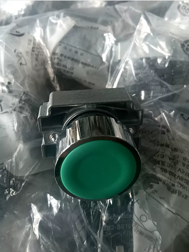

Explicația modelului
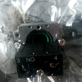
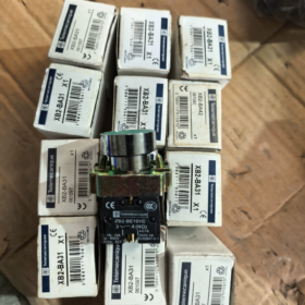
XB2-BA31C (Complete ordering model; sufix “C” cannot be omitted)
XB2: Harmony XB2, 22 mm metal pushbutton series
BA: Flush head, spring return pushbutton
3: Verde
1: 1 Contact în mod normal deschis (1NU)
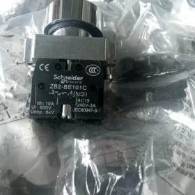
Component breakdown: ZB2BA3C (pushbutton head) + ZB2BZ101C (1NO contact block)
- Specificatii tehnice principale
| Articol | Parametru |
| Mounting cutout diameter | Φ22 mm standard panel cutout |
| Tipul operațiunii | Retur de primăvară (momentary, automatically rebounds upon release) |
| Pushbutton colour | Verde (standard start pushbutton) |
| Configurarea contactului | 1NU (Deschis normal, terminale 3-4) |
| Bezel material | Chrome-plated metal, rezistent la impact |
| Gradul de protecție | IP65 (front panel side) |
| Rated thermal current | 10 O, rated insulation voltage Ui = 600 V |
| Rezistenta mecanica | ≥ 3 milioane de operațiuni |
| Temperatura de functionare | -25 ℃ ~ +55 ℃ |
| Wiring type | Conexiune terminală cu șurub |
- Aplicații tipice
Start pushbutton for industrial control cabinets: pornirea motorului, equipment operation triggering, jog control circuits.
Matching reference: Red stop pushbutton XB2-BA42C (1NC)
- Common Flush Pushbuttons of the Same Series
XB2-BA11C: Alb, 1NU
XB2-BA21C: Negru, 1NU
XB2-BA31C: Verde, 1NU (acest model)
XB2-BA41C: Roşu, 1NU; XB2-BA42C: Roşu, 1NC
XB2-BA51C: Galben, 1NU
XB2-BA61C: Albastru, 1NU
- Note de instalare
- Applicable panel thickness: 1~6 mm
- Recommended tightening torque for mounting nut: 0.8 N·m
- For additional contacts, stack ZB2-BE101 (NU) / ZB2-BE102 (NC) contact modules
- This model has no built-in indicator light; for illuminated green start pushbutton, select XB2BW33C series
Complete Installation Procedure for Schneider XB2-BA31C (XB2-BA31)
Component composition: ZB2BA3C (green flush pushbutton head) + ZB2BZ101C (1NO contact block)
Precondiții & Instrumente
- Panel Requirements
Decupaj standard: Φ22 mm, deburred cutout without sharp edges
Applicable panel thickness: 1~6 mm
Minimum centre spacing between adjacent pushbuttons: ≥ 30 mm
- Instrumente necesare
Flat screwdriver (PH1), dispozitiv de dezimbrare; torque screwdriver recommended
- Official Standard Torque Values
Pushbutton mounting nut: 0.8 N·m (Do NOT over-tighten)
Terminal screws: 0.5~0.8 N·m
- Specificația cablului
Recommended 0.5~1.5 mm² stranded copper control cable, stripping length 7~10 mm
Step-by-Step Standard Installation Sequence
⚠️ First step for all electrical work: Cut off main power supply of control cabinet, implement lockout & tagout!
Pas 1: Parts Inventory & Inspecție vizuală
Check complete set after unpacking:
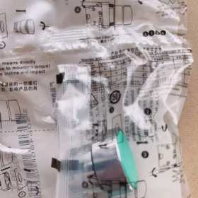
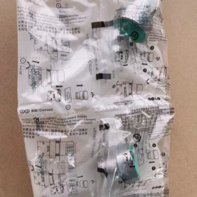
- Green pushbutton operating head ZB2BA3C (equipped with sealing gasket to ensure IP65 protection)
- Metal locking nut
- Contact block ZB2BZ101C (1NU)
Verify sealing gasket intact and plastic latches free from cracks.
Pas 2: Insert Pushbutton Head into Control Panel (Install from FRONT of panel)
- Fit sealing gasket properly onto the rear shoulder of pushbutton head (gasket cannot be omitted or twisted)
- Insert pushbutton head into Φ22 mm cutout from outer (faţă) side of panel
- Threaded shank extends out from rear panel; keep pushbutton head closely attached to panel surface without tilt
Pas 3: Mount locking nut to secure pushbutton head
- Screw metal locking nut onto threaded shank from rear side, hand-tight until touching panel
- Tighten evenly with tool, maintain torque at 0.8 N·m
✅ Acceptance criteria: Pushbutton free of wobble, smooth pressing without jamming
❌ Do not apply excessive force! Over-tightening will crack sealing gasket, cause pushbutton seizure and void IP65 protection.
Pas 4: Snap-fit contact block (Most frequent assembly error point)
- Two elastic latches on contact block front side align with slots on rear of pushbutton head
- Push contact block horizontally and straightly; two audible “clic” sounds confirm full engagement of both latches
❗ Do not pry diagonally or force press violently; broken latches require replacement of contact block
✅ Removal method: Pry both side latches gently with flat screwdriver and pull contact block backward
Pas 5: Funcționarea cablajului (XB2-BA31, 1NO contact)
Terminal marking printed on contact block:
Terminale 3, 4 = Normally Open (NU): Open circuit at rest, closed when pressed
- Strip cable insulation, prevent loose copper strands and burrs
- Insert conductor into terminal hole; ensure insulation is not clamped under screw
- Tighten terminal screw clockwise (torque 0.5~0.8 N·m)
- Light traction test on cable to confirm no looseness; exposed copper strands may lead to short circuit risk
Pas 6: Mechanical test before power-on (Mandatory procedure)
- Press pushbutton repeatedly: funcționare lină, instant automatic rebound after release, no sticking or abnormal noise
- Visually confirm contact block latches fully locked to avoid detachment under vibration
- Check sealing gasket fits panel evenly without gaps (critical for dust & rezistenta la apa)
Pas 7: Continuity test before energization
Use multimeter continuity mode to test terminals 3 şi 4:
Rest state: Circuit deschis (rezistență infinită)
Push and hold pushbutton: Conductiv (resistance close to 0 Oh)
Only proceed to switch on power after passing test.
Typical Wiring Reference (Standard Start Circuit)
Control power supply → Terminal 3
Terminal 4 → Contactor coil / PLC digital input
Push button pressed → Terminals 3-4 conduită, start signal triggered
Common Installation Mistakes & Warnings
- Lipsă / distorted sealing gasket → Loss of IP65 rating; dust and moisture ingress leads to contact oxidation and poor conductivity
- Excessive torque on mounting nut → Internal mechanism compressed, pushbutton fails to rebound
- Diagonally forcing contact block → Plastic latches fracture; contact block may fall off during equipment operation
- Over-stripped cable and loose copper strands → Risk of short circuit between adjacent terminals
- Panel cutout larger than Φ22.2 mm → Pushbutton wobbles and sealing fails
- Do not mount contact block first then pass pushbutton through panel! Correct sequence: Secure pushbutton head to panel first, then attach contact block
Disassembly Procedure (For contact maintenance & înlocuire)
Cut off power → Pry two latches of contact block with flat screwdriver → Pull contact block backward;
To remove complete pushbutton: Unscrew rear locking nut, extract pushbutton head from panel front.
Operating Principle of Schneider XB2-BA31C (XB2-BA31)
Component composition: ZB2BA3C (green spring return pushbutton head) + ZB2BZ101C (1NO contact block)
It is a mechanical momentary pushbutton without indicator light.
- Mechanical Operating Principle
- Initial state (Unpressed)
Built-in compression spring pushes operating head outward and maintains extended position. Internal moving contact is separated from stationary contact.
- Actuation state (Push down button)
External force depresses green pushbutton head → Internal pushrod travels backward → Drives movable contact bridge inside contact block to displace
Contact bridge connects two stationary contacts simultaneously, terminale 3 şi 4 (NU) închis.
- Release state (Automatic return)
When external pressure disappears, built-in spring rebounds and resets pushrod; contact bridge retracts, contacts separate again, circuit between 3 şi 4 opens.
Caracteristică: Momentary type (jog operation), non-latching; conductive only while being pressed.
- Electrical Principle (XB2-BA31: 1NU Deschis normal)
Terminal marking on contact block: 3, 4 = Normally Open (NU)
Static status: Circuit open between 3 şi 4 (rezistență infinită)
Push button: Circuit closed between 3 şi 4
Upon release: Circuit restores open state instantly
Contacts are passive mechanical dry contacts:
No built-in power supply; only switches on/off external control circuits. Compatible with low-voltage AC/DC control loops (bobine de contactor, PLC DI inputs, relay circuits).
- Brief Internal Structure Breakdown
- Pushbutton housing + arc de întoarcere
- Transmission pushrod (transmit pressing force)
- Blocarea contactului: Fixed stationary contacts + movable conductive contact bridge
- Screw wiring terminals
Force transmission sequence:
Manual pressing → Pushbutton head → Pushrod compresses spring → Contact bridge displacement → Contacts closed
Release button → Spring extends and resets → Contact bridge retreats → Contacts open
- Caracteristici cheie
- No built-in indicator lamp, no lighting power supply required; distinguish from illuminated model XB2BW33C.
- Pure physical mechanical contact switching without electronic components, performanță puternică anti-interferență.
- IP65 protection relies on front sealing gasket to prevent water vapour and dust entering contact cavity.
- Typical Application Logic (Motor Start Circuit Example)
Control live L → Terminal 3
Terminal 4 → Contactor KM coil → Neutral N
When XB2-BA31C is pressed → KM coil energizes, contactor pulls in;
Pushbutton circuit opens upon release, continuous operation maintained by self-locking via auxiliary NO contact of contactor.
Neînțelegeri comune
❌ Not a latching pushbutton: Circuit opens after release, cannot sustain conduction status
❌ Not suitable as limit switch under continuous compression; accelerates spring fatigue
❌ Contacts only serve control circuits, cannot directly drive high-power loads





NH42-63-318x560.png "Comutatoare de transfer automat de tip PC CHINT (ATS)NH42-63/4SZ")



