 Contactor,întrerupător de circuit,senzor,Codificator,PLC,Convertor

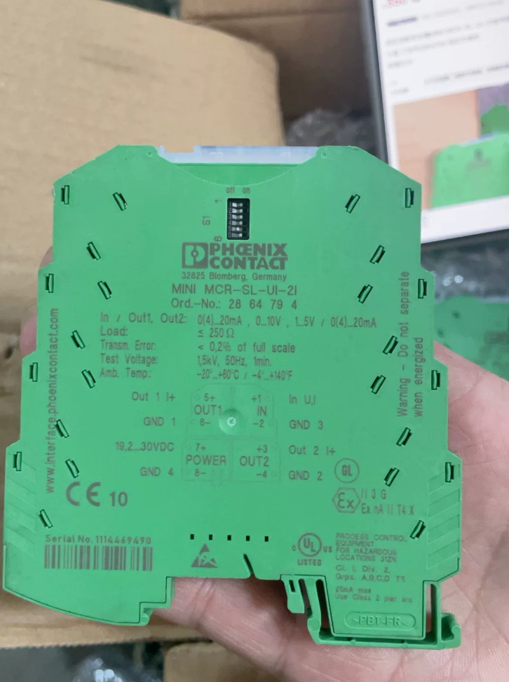

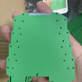
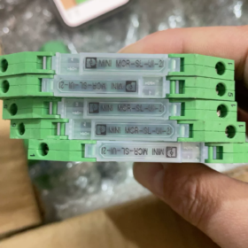
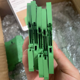
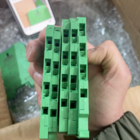
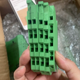
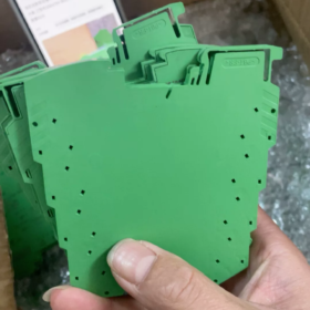
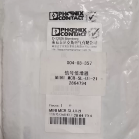
Model complet:MINI MCR-SL-UI-2I
Phoenix Contact analog signal isolator-splitter (signal replicator), Montare pe șină DIN, 1-channel input, 2-channel isolated current output
Informații de bază
| Articol | Parametru |
| Comanda nr. | 2864794 |
| Seria de produse | MINI MCR‑SL |
| Lățimea carcasei | 6.2 mm ultra‑slim |
| Montare | DIN‑35 rail |
| Cablaj | Borne cu șuruburi |
| Alimentare electrică | 24 VDC |
| Izolare | Input‑Output‑Power supply three‑way isolation |
Signal Specifications
Intrare (DIP-switch configurable):0-20mA / 4-20mA / 0-10V / 1-5V
Two independent current outputs:0-20mA / 4-20mA. The two outputs are mutually isolated for simultaneous acquisition by PLC and recorder systems.
Funcții:Signal isolation, 1-to-2 signal splitting, anti-interferență, potential difference isolation, signal conversion & replication
Precizie:Typical <0.1 %
Aplicație:Transmitter signal splitting; one sensor signal fed simultaneously to controller and display / recording devices
Scenarii tipice de aplicare
- AI analog loop 1-in-2-out: one 4-20 mA sensor connected to both PLC AI module and paperless recorder
- Potential difference isolation between field instruments and control cabinet to eliminate ground-loop interference
- High-density installation in compact cabinets with 6.2 mm slim housing
Înlocuire & Reference Alternatives
Intra-series replacement: verify input and output types. This part number is not obsolete; both new and used units are available on market.
Echivalentul intern: DIN-rail signal isolator-splitter, 1-in-2-out 4-20 mA
Ghid de depanare
- Fără ieșire: Check 24 VDC power supply; confirm DIP-switch input range matches field signal.
- Inaccurate output: Check loop load resistance; max. current-output load approx. 500 Oh.
- Fluctuația semnalului: Verify integrity of three-way isolation; inspect field earthing conditions.
Application Scenarios of Signal Isolator-Splitter
Signal isolator-splitter (1-input multi-output, typical 1-in-2-out such as Phoenix 2864794 MINI MCR-SL-UI-2I). Core capabilities: galvanic isolation for ground-loop suppression + replication of one analog signal into multiple independent outputs. Mainly used for industrial 4-20 mA and 0-10 V analog loops.
- Signal Splitting for Multi-System Acquisition (Cele mai comune)
One sensor signal feeds two sets of equipment without mutual influence
- Field transmitters (presiune, nivel, temperatură, curgere, 4-20 mA) → one channel to PLC AI module, the other to paperless recorder, digital indicator or DCS system.
- Valve position feedback signal routed to both local indicator and control system.
Direct parallel connection without isolator-splitter will cause signal attenuation, measurement deviation and ground-potential conflict between devices.
- Ground-Loop Interference Suppression for Drifting / Jittering Signals
Field instruments, PLC and DCS may connect to separate earth points. Potential difference between grounding points creates ground loops, resulting in analog signal jitter, zero-point drift and unstable readings.
Isolator-splitter provides galvanic isolation among input, outputs and power supply to break ground loops.
Industrii tipice: linii de producție la scară largă, tratarea apei, metalurgie, power plants with long analog signal cabling.
- Signal Interfacing Between Independent Systems
Analog signal exchange between different control systems:
Analog output from PLC-A sent to PLC-B and third-party devices, where both systems have separate earthing networks and cannot share a common ground.
Nota: Standard isolator-splitters are not intrinsically safe. Select IS-certified models for hazardous-area instrument signal transfer into non-hazardous cabinets.
- Combined Signal Conversion & Splitting
Convert voltage input to multiple current outputs, or convert 4-20 mA input to multiple 0-10 V outputs; realize signal format conversion together with multi-channel replication.
Exemplu: Field 0-10 V pressure signal converted into two 4-20 mA outputs for remote acquisition modules.
- Equipment Protection against Common-Mode Surge Interference
When analog cables run alongside power cables, motor and VFD switching generates common-mode interference and transient surges. Isolation blocks interference from entering PLC AI cards, protecting expensive input modules and reducing failure risk.
- High-Density Installation in Compact Control Cabinets
Slim-width modules such as Phoenix MINI series (6.2 mm) allow dense DIN-rail mounting for small cabinets and cabinet retrofits without consuming excessive cabinet space.
- Plant Retrofit Projects
Add a new monitoring system without modifying existing sensor wiring. Install isolator-splitter to replicate signal; no field-instrument replacement required.
Distinguish Similar Devices
- Signal isolator-splitter: 1-input multi-output, performs signal replication and splitting
- Signal isolator: 1-in-1-out, asigură izolare & conversion without signal splitting
- Signal converter: Performs voltage-current conversion, may lack galvanic isolation and cannot replicate multiple outputs
Note de aplicare
- Current-output channels have maximum load-resistance limits; overload causes signal distortion.
- Set DIP-switches to match actual input signal type (4-20 mA / 0-10 V).
- For explosion-hazard environments, use intrinsically-safe certified models; general-purpose isolator-splitters shall not be used in hazardous-area loops.
Working Principle of Signal Isolator-Splitter
Take Phoenix 2864794 (MINI MCR-SL-UI-2I), a 3-way-isolated 1-in-2-out isolator-splitter as example.
Principiul de bază: No direct conductive connection among input, power supply and outputs. Signals are transferred via magnetic or opto-coupling, while one raw analog signal is replicated into multiple independent analog outputs.
Four functional blocks: Input conditioning → Isolation coupling → Signal replication circuit → Multi-channel output unit, plus isolated power supply.
- Input Signal Conditioning
Field analog signals (4-20 mA, 0-10 V etc.) enter the input circuit:
DIP-switches select signal type and measuring range.
Filter circuits suppress high-frequency noise; I-V conversion converts incoming current into internal voltage signal.
Sampling generates internal voltage proportional to input magnitude.
The input side is galvanically isolated from subsequent circuitry.
- Isolation Coupling (Core Isolation Stage)
High-accuracy industrial isolation amplifiers mostly adopt magnetic coupling (transformer isolation), older units may use opto-couplers.
Conditioned analog signal is modulated onto high-frequency AC carrier.
Signal is transmitted by magnetic field through miniature isolation transformer; no conductive copper path between primary and secondary windings.
Transformer primary belongs to input side; secondary belongs to output side. Ground-loop paths are broken and cross-site ground-potential differences are blocked.
Power supply also passes through independent isolating transformer to feed output-side circuitry, achieving three-way isolation: intrare, output and power supply.
⚠️ General opto-couplers exhibit poor linearity. High-accuracy MCR series deploy magnetic isolation to guarantee 0.1 %-level precision.
- Demodulation & Signal Restoration
High-frequency carrier passing across isolation barrier is demodulated, restoring analog reference signal identical in magnitude to original field input.
- Signal Replication (Splitter-Specific Function)
This stage differentiates splitter from ordinary single-channel isolators.
High-precision op-amp circuits create two mutually-independent output drive channels from the single reference signal:
Two output channels are galvanically isolated from each other.
Each channel independently drives downstream loads (PLC, recorder, digital indicator).
Short-circuit or fault on one output will not affect the other output or the original field sensor input.
Ordinary 1-in-1-out isolator: only one output driver stage.
Isolator-splitter: additional multi-channel replication driver circuitry.
- Multi-Channel Output Driver
Replicated reference signals are converted to current (4-20 mA / 0-20 mA) or voltage outputs for downstream equipment.
Current outputs are subject to maximum load-resistance constraints; excessive load resistance results in distorted output.
Simplified Summary
Instead of directly paralleling one sensor signal to two receivers (which causes current-sharing errors and ground-potential interference), the isolator-splitter reads the incoming signal, provides galvanic separation from field side, internally generates two identical fresh signals and feeds them separately to two systems. The sensor only needs to drive the isolator-splitter as its single load.
Ground-Loop Suppression Principle
Field instrument connects to earth-point A; PLC connects to earth-point B. Potential difference between A and B may reach tens of volts. Direct wiring creates circulating current in signal lines and produces measurement jitter. The isolation transformer breaks the conductive path between input-side ground and output-side ground, eliminating circulating ground-loop current.
Comparative Table
| Dispozitiv | Key Principle |
| Signal isolator | Input‑side isolation, o singură ieșire, no signal replication |
| Signal isolator‑splitter | Galvanic isolation + internal signal replication for multiple independent outputs |
| Signal converter | Voltage‑current conversion, no guaranteed galvanic isolation |
Note cheie
- Isolation suppresses common-mode interference but cannot eliminate noise inherent in the original signal. Separate analog wiring from power cables is still required.
- Magnetically-isolated modules require external 24 VDC for isolated auxiliary power.
- Multi-channel outputs are electronically replicated internally, not simple parallel shunting of input loop.
Isolation-Voltage Specifications for Phoenix 2864794 (MINI MCR-SL-UI-2I)
Four-way isolation: Intrare, Output-1, Output-2 and power supply are mutually isolated; Basic Insulation per EN 61010.
| Articol | Valoare | Observații |
| Dielectric test voltage | 1.5 kV AC, 50 Hz, 1 min | Factory type test; applies to input‑to‑output, input‑to‑power, output‑to‑power and between the two output channels. |
| Tensiunea nominală de izolație Ui | 50 V AC/DC | Maximum continuous common‑mode voltage permitted across isolation barrier; not the short‑term test voltage. |
| Clasa de izolare | Basic Insulation | For instrument anti‑interference only. Not for personal‑safety protection. |
Critical distinction frequently misunderstood on-site:
- 1.5 kV AC /1 min test voltage: Short-duration factory withstand test value. Do not apply 1500 V continuously across isolation barrier during operation.
- Rated insulation voltage Ui =50 V AC/DC: Maximum long-term permitted common-mode potential difference across isolation. Field ground-potential difference should preferably stay well below 50 V.
Industry-Typical Isolator-Splitter Isolation-Voltage Comparison
| Model Type | Dielectric Test Voltage | Tensiune nominală de izolație | Note |
| Phoenix MINI‑SL series (2864794) | 1.5 kV AC /1 min | 50 V AC/DC | Ultra‑slim 6.2 mm, basic isolation for process‑instrument anti‑interference |
| Phoenix new‑generation MINI‑2 enhanced series | 2.5 kV AC /1 min | 300 V AC/DC | Reinforced insulation for larger ground‑potential differences |
| General domestic isolator‑splitter | 1.5‑2 kV AC /1 min | 250 V AC | 250 V denotes rated insulation voltage for most domestic products |
Engineering Application Guidelines
- This module suppresses ground-loop and common-mode interference only and is not a safety-isolation device. Long-term cross-isolation-barrier potential shall not exceed 50 V. Select enhanced-insulation models if site ground-potential difference frequently exceeds 50 V.
- 1.5 kV applies only to short-time withstand testing; transient voltage spikes may be tolerated but continuous high-voltage operation is forbidden.
- Four-way isolation definition: Intrare, Output-1, Output-2 and 24 V power supply are pairwise isolated. Short-circuit on one output will not affect the other output or input signal.
Relationship Between Isolation Voltage and Ambient Temperature for Signal Isolator-Splitter
Analysis based on Phoenix 2864794 MINI MCR-SL-UI-2I. Differentiate rated insulation voltage (funcţionare pe termen lung), dielectric withstand test voltage (1-minute short-term test), and intrinsic breakdown voltage of insulating material.
- Datasheet-published parameters are temperature-independent within rated operating range
1.5 kV AC /1 min dielectric withstand test: Performed at reference 25 °C for factory type-approval only, not operational continuous voltage.
Rated insulation voltage Ui = 50 V AC/DC: Maximum allowable continuous common-mode voltage across isolation barrier. Within full published operating temperature range (-20 °C ~ +60 °C), datasheet parameters require no temperature-derating.
✅ Apply datasheet values directly when module operates within specified temperature range. Do not arbitrarily derate Ui to a lower value merely because cabinet temperature rises to 45 °C.
- Physical mechanism: Insulating-material breakdown voltage decreases at higher temperature
Isolation is realized by insulating dielectrics inside miniature pulse transformers (polymer films, magnet-wire enamel coatings).
Rising ambient temperature increases molecular mobility inside insulation materials; intrinsic material breakdown voltage declines, and instantaneous high-voltage withstand capability drops.
Industrial modules are designed with substantial safety margin: within -20 °C ~ +60 °C, real-world breakdown margin remains far above 1500 V test level; hence datasheet does not publish derating curves.
When ambient temperature continuously exceeds maximum rated +60 °C: Insulation aging accelerates; practical withstand capability degrades significantly. Long-term over-temperature operation raises risk of isolation-barrier failure and ground-loop-suppression loss.
⚠️ Distinguish clearly: Signal accuracy / temperature drift ≠ isolation withstand capability. Temperature-dependent measurement drift arises from signal-processing circuitry; isolation-voltage performance depends on dielectric materials, these are independent metrics.
- Temperature-dependence comparison table
| Parametru | Behavior within ‑20~+60 °C rated range | Condition above +60 °C over‑temperature |
| 1.5 kV AC 1 min (dielectric test) | Datasheet value unchanged; physical safety margin of insulation reduces | Instantaneous high‑voltage withstand capability drops; dielectric test may fail |
| Tensiunea nominală de izolație Ui (50 V for this model) | No datasheet‑mandated derating; use full Ui rating | Insulation aging accelerates; continuous full‑Ui operation is not recommended |
| Signal accuracy / thermal drift | Measurement error varies with temperature (tens of ppm/°C) | Measurement error further increases |
- Practical on-site engineering guidance (for MINI-SL series such as 2864794)
- Maintain module surrounding temperature between -20 °C ~ +60 °C. Within this range, apply datasheet values of 1.5 kV test withstand and 50 V rated insulation voltage without manual derating.
- If cabinet cooling is poor and module ambient temperature persistently exceeds +60 °C:
Immediate failure is not guaranteed, yet insulation aging accelerates and safety margin shrinks. Ground-loop-rejection performance deteriorates; long-term isolation-failure risk rises. Improve cabinet ventilation or adopt MINI-2 wide-temperature-range series.
- Rated insulation voltage Ui = 50 V represents a hard application limit, regardless of temperature. Cross-barrier ground-potential difference should preferably stay well below 50 V. If site ground-potential difference regularly approaches or exceeds 50 V, do not rely on cooling for mitigation; upgrade to higher-Ui model e.g. MINI MCR-2 series with Ui = 300 V.
- Low-temperature operation (-20 °C): Insulation withstand capability slightly improves with no adverse effects.
- Concepții greșite comune
❌ Concepție greșită: At cabinet temperature 45 °C, the 1.5 kV test rating can be treated as operational continuous voltage, allowing 1000 V across isolation barrier.
✔ Correction: 1.5 kV is a short-duration destructive factory-test value and must never be applied continuously in operation under any temperature. Always refer to rated insulation voltage Ui for continuous-service conditions.
❌ Concepție greșită: Apply proportional derating factor to Ui whenever temperature rises moderately.
✔ Correction: Use full datasheet Ui rating within manufacturer-specified temperature window. Over-temperature calls for reliability-lifetime assessment and thermal improvement instead of simple arithmetic derating.
Brief Summary
Datasheet-specified isolation-voltage ratings remain valid within published operating-temperature range. Physically, insulating-material high-voltage margin reduces as temperature rises, which is offset by product-design safety margin. Primary risk comes from sustained operation above maximum rated ambient temperature: accelerated insulation aging and degraded isolation reliability, rather than direct modification of datasheet parameter numbers.





NH42-63-318x560.png "Comutatoare de transfer automat de tip PC CHINT (ATS)NH42-63/4SZ")



