 Contactor,întrerupător de circuit,senzor,Codificator,PLC,Convertor

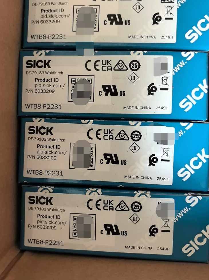

Cablu drept de 4 m: YF8U14-040VA3XLEAX
Cablu drept de 5 m: YF8U14-050VA3XLEAX
Baza conectorului: STE-0804-G (bloc terminal pentru cablarea cabinetului de comandă)
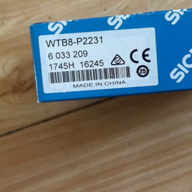
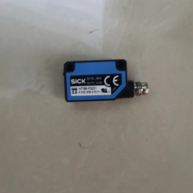
Instalare completă & Manual de punere în funcțiune pentru SICK Senzor fotoelectric WTB8-P2231 (Ordin Nr.6033209)
- Informații de bază despre model
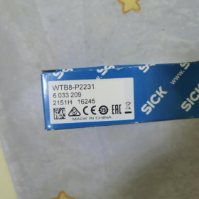
Model complet nr.: WTB8-P2231
Ordinul Oficial nr.: 6033209
Serie: W8 Ultra-compact difuz Senzor fotoelectric cu Suprimarea fundalului
Origine: China
Accesorii standard: Suport de montare din oțel inoxidabil BEF-W100-A
Defalcarea codului de model
- WT: Senzor fotoelectric cu reflexie difuză
- B: Echipat cu funcție de suprimare a fundalului
- 8: Carcasa miniaturala W8 (11×31×20mm)
- P: Ieșire PNP
- 22: Conector M8 drept cu 4 pini, sursa de lumina LED rosu
- 31: 4-reglaj potențiometru de rotație, Lumină aprinsă / Întuneric comutabil
- Specificații optice de bază
| Element de parametru | Caietul de sarcini |
| Principiul detectării | Reflexie difuză + suprimarea fundalului |
| Sursă de lumină | LED roșu vizibil, 650nm |
| Interval de detectare standard | 40~300 mm (90% hârtie albă cu reflexie ridicată) |
| Distanța minimă de suprimare | 30mm (Filtrează fundalul la distanță apropiată) |
| Dimensiunea spotului la 300 mm | Φ20mm |
| Metoda de ajustare | 4-potentiomsicketer de precizie |
| Modul de operare | Lumină comutabilă aprinsă / Întuneric |
III. Specificații electrice
- Alimentare electrică: DC 10~30V, ondulație ±10%
- Ieșire: PNP colector deschis, max. sarcina 100mA
- Curent de repaus: ≤30mA
- Timp de răspuns: ≤0,5 ms
- Frecvența de comutare: 1000Hz (pentru detectarea obiectelor de mare viteză)
- Protecţie: Polaritate inversă, supracurent & tripla protectie la scurtcircuit
- Durata de viață: 100,000 ore pentru sursa de lumină LED (25℃)
- Definiția cablajului M8 cu 4 pini (Conector drept)
Culoare pin & funcţie (cablu standard cu 4 fire):
- BN Brown: DC24V+ (L+)
- WH Alb: Pin nefolosit (nicio conexiune)
- BU Albastru: 0V Negativ (M/GND)
- BK Negru: Ieșire semnal PNP Q
- Mecanic & Specificații de mediu
Dimensiuni: L11mm × H31mm × D20mm
Greutate: Doar 10 g
Materialul carcasei: Plastic ABS; fereastra optică: PMMA
Clasa de protectie: IP67 (rezistent la praf, rezistent la scufundare temporară în apă)
Temperatura de operare: -25℃ ~ +55℃
Temperatura de depozitare: -40℃ ~ +70℃
Montare: Se fixează prin găuri filetate simetrice M3 pe ambele părți
- Indicator LED Descriere
- LED verde: Aprins continuu = alimentare normală; Clipește = Detectare instabilă
- LED portocaliu: Iluminat = Ieșirea senzorului activată (obiect detectat)
VII. Avantajele de bază
- Suprimare puternică a fundalului: Elimină interferența din ramele metalice, benzi transportoare, pereți și alte fundaluri, asigură o detecție stabilă pentru negru & piese de prelucrat albe
- Dimensiune ultracompacte: Instalare ușoară în echipamente înguste, module de conducte și roboți de prindere
- Răspuns de mare viteză: Ideal pentru ambalare, sortarea și numărarea pieselor mici
- Praf IP67 & rezistenta la apa, funcționare stabilă în uleiuri & condiții umede de atelier
- 4-potențiometrul de rotație permite reglarea fină de înaltă precizie pentru ajustări minore ale distanței
VIII. Scenarii tipice de aplicare
Detectarea prezenței materialelor pe liniile de producție a ambalajelor
Numărând & confirmarea poziției componentelor hardware/plastic mici
Prevenirea scurgerilor de detectare a produselor pe benzile transportoare
Poziţionarea piesei de prelucrat în interiorul echipamentelor electronice
Sortarea articolelor mici în sistemele logistice
- Alternativă / Modele distincte din aceeași serie
- WTB8L-P2231: Versiune laser cu carcasă identică, punct de lumină mai mic pentru detectarea de înaltă precizie la distanță lungă
- WTB8-N2231: Varianta de ieșire NPN (pentru intrare comună negativă PLC)
- WTB8-P1301: Ieșire cablu M8 cot, pentru instalare cu spațiu limitat
- WTB8-P2231V: Carcasă sanitară din oțel inoxidabil (pentru medii umede de procesare a alimentelor)
- Cabluri potrivite recomandate
Cuprins
- Instrucțiuni de siguranță
- Unboxing Standard Piese Listă
- Specificații de instalare mecanică (Paranteză, Cuplu, Dimensiuni, Cerințe de autorizare)
- Definiția cablajului electric M8 cu 4 pini & Proceduri de cablare
- Alinierea optică la fața locului & Operații de reglare a distanței
- Lumină aprinsă / Comutarea modului întunecat
- Indicator LED Stare Explicație
- Interdicții de instalare de mediu & Cerințe de protecție
- Întreținere de rutină & Standarde de curățare
- Matricea de depanare
- Selectarea cablurilor potrivite & Piese de schimb
- Instrucțiuni obligatorii de siguranță
- Opriți sursa de alimentare DC24V înainte de cablare. Conectarea/deconectarea la cald a conectorului M8 este interzisă pentru a evita defectarea cipului de ieșire.
- Gama nominală de alimentare este limitată la DC 10~30V; Intrarea AC220V sau AC110V este strict interzisă, care va arde senzorul instantaneu.
- Max. sarcina de ieșire este de 100 mA. Acționarea directă a electrovalvelor sau contactoarelor este interzisă; adăugați izolarea releului dacă trebuie conduse sarcini de mare putere.
- Foraj, slefuirea sau dezasamblarea carcasei senzorului este interzisa. Garnitura IP67 deteriorată va duce la pierderea performanței rezistente la praf și la apă.
- Preveniți lumina puternică să iradieze direct fereastra optică (lumina soarelui, arc de sudare, spoturi de mare putere), care cauzează declanșarea falsă și eșecul de detecție.
- Evitați impactul puternic sau căderea; calea optică internă decalată va degrada permanent stabilitatea detectării.
- Unboxing Standard Piese Listă
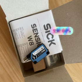
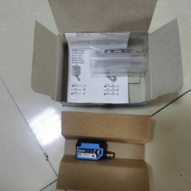
Unitatea principală cu senzor: WTB8-P2231 ×1
Accesoriu de montare standard: Suport din oțel inoxidabil BEF-W100-A ×1
Șuruburi de fixare M3, şaibe plate & şaibe elastice (livrat cu suport)
Fără cablu furnizat din fabrică; Cablul drept M8 cu 4 pini va fi achiziționat separat
- Specificații de instalare mecanică
3.1 Dimensiuni generale
L11mm × H31mm × Adâncime 20mm; găuri de montaj filetate interne simetrice M3 pe ambele părți.
3.2 Etape de montare a suportului
- Fixați suportul BEF-W100-A pe tabla de echipament sau extrudarea aluminiului și strângeți în prealabil șuruburile.
- Fixați senzorul în fanta suportului, aliniați găurile M3 bilaterale, și treceți prin șurubul M3, şaibă plată şi şaibă elastică.
- Cuplu de strângere standard: 1.8 Nm
Cuplu insuficient: Vibrația provoacă decalarea senzorului și deplasarea punctelor de lumină;
Cuplu excesiv: Decuparea firelor, deformarea carcasei și dezalinierea traseului optic.
- Reglați fin pe verticală & unghiurile orizontale ale senzorului pentru a acoperi complet suprafața țintă cu un punct de lumină roșie, apoi blocați toate șuruburile.
3.3 Cerințe de autorizare pentru instalare (Critic pentru suprimarea fundalului)
- Rezervați un spațiu minim de 30 mm între fereastra optică a senzorului și fundalul spate fix; în caz contrar, interferența de fundal duce la un semnal ON fals permanent.
- Raza standard de detectare: 40~300 mm (90% obiect alb cu reflexie ridicată); 30~40 mm este un interval critic susceptibil la interferența materialului.
- Nu așezați metal, oglindă sau panouri cu reflexie ridicată aproape în spatele senzorului; reflexia difuză intensă va dezactiva suprimarea fundalului.
- Instalarea conductei: Aliniați punctul luminos cu centrul piesei de prelucrat, evitați îmbinările transportoarelor, role și suporturi metalice.
- Senzori multipli montați unul lângă altul: Distanța dintre senzori adiacenți ≥50 mm pentru a preveni interferențele reciproce de diafonie a luminii roșii.
3.4 Permis / Medii de instalare interzise
✅ Permis: Atelier uscat, praf usor, pulverizare intermitentă cu apă (Rezistenta temporara la apa IP67), mediu de -25℃~+55℃
❌ Interzis: Imersie continuă, acid coroziv puternic/lichid alcalin, stropire de ulei de tăiere pe termen lung, temperatura peste +55℃ sau sub -25℃, zone de lângă dulapuri electromagnetice grele (invertoare, motoare de mare putere)
- Specificații cablare electrică
4.1 Conector drept M8 cu 4 pini Definiție pin fix
| PIN nr. | Culoarea firului | Funcţie | Instrucțiuni de cablare |
| 1 | BN Brown | DC24V pozitiv L+ | Borna de ieșire a sursei de comutare |
| 2 | WH Alb | Pin nefolosit | Lasă plutitor, nu conectați la curent sau la masă |
| 3 | BU Albastru | 0V GND negativ | Putere negativă & Terminal comun PLC |
| 4 | BK Negru | Ieșire PNP Q | Terminal de intrare digitală PLC (PNP activ la nivel înalt) |
4.2 Etapele operației cablajului
- Confirmați întreruperea sursei de alimentare, introduceți conectorul M8 direct în fanta de la coada senzorului, strângeți firul în sensul acelor de ceasornic fără forță brută.
- Dirijați cablurile departe de cablurile de alimentare și liniile de ieșire ale invertorului cu o separare ≥10 cm pentru a evita interferențele electromagnetice.
- Raza de îndoire a cablului ≥5× diametrul exterior al cablului; plierea tare sau extrudarea pe termen lung a rădăcinilor cablului este interzisă.
- Montați o siguranță lentă de 4 A în circuitul de alimentare pentru a proteja senzorul împotriva deteriorării prin scurtcircuit.
4.3 Instrucțiuni de potrivire a ieșirii PNP
Conectați borna comună de intrare a PLC-ului la 24V negativ; conectați firul negru de semnal al senzorului direct la punctul de intrare PLC. Nu este necesar un rezistor extern de tragere.
- Alinierea optică & Reglarea distanței (4-Potențiometrul de precizie rotit)
5.1 Operația de aliniere
- După pornire, LED-ul de alimentare verde rămâne fix; observați punctul roșu de lumină în partea din față.
- Reglați unghiul senzorului pentru a acoperi complet piesa țintă, fără ca un punct parțial să cadă pe suportul de fundal.
5.2 Debit de reglare potențiometru (Calibrarea suprimarii fundalului)
- Așezați piesa țintă la distanța maximă de detectare (300mm), Rotiți încet potențiometrul în sensul acelor de ceasornic până când LED-ul portocaliu de ieșire se aprinde.
- Scoateți piesa de prelucrat, LED-ul portocaliu trebuie să se stingă; dacă rămâne aprins, există interferențe de fundal — măriți distanța dintre senzor și fundal sau reglați fin potențiometrul în sens invers acelor de ceasornic.
- Repetă plasarea & scoaterea piesei de prelucrat pentru verificare: LED-ul se aprinde când piesa de prelucrat este prezentă, se stinge când lipsește, nicio clipire frecventă înseamnă că calibrarea a fost finalizată.
- Potențiometrul acceptă reglarea în 4 ture cu precizie de reglare fină ridicată; evitați rotația excesivă de fiecare dată.
- Lumină aprinsă / Comutarea modului întunecat
Comutator mic pe partea senzorului:
L (Lumină aprinsă): Ieșire ON când punctul luminos este blocat de obiect (LED portocaliu aprins), modul implicit pentru detectarea prezenței piesei în conductă.
D (Întuneric): Ieșire ON când nu există niciun obiect; semnal întrerupt la sosirea piesei de prelucrat, potrivit pentru poziție goală & alarma material lipsa.
- Tabel de stare cu LED-uri cu două culori
| LED verde (Putere) | LED portocaliu (Ieșire) | Starea echipamentului | Metoda de manipulare |
| Pornit constant | OFF | Putere normală, nu a fost detectat niciun obiect | Standby normal |
| Pornit constant | Pornit constant | Obiect detectat, ieșire activată | Detectare normală |
| Pornit constant | Clipește rapid | Detectare instabilă (interferența de fundal, distanta peste raza de actiune, compensare spot) | Recalibrați potențiometrul & reglați distanța de montare |
| OFF | Orice Stare | Fără putere, fir rupt sau pană de curent | Inspectați firele maro/albastre, 24V sursă de alimentare și siguranță |
| Intermitent | Orice Stare | Subtensiune / ondulație excesivă de putere | Înlocuiți sursa de alimentare reglată DC24V, reduce căderea de tensiune a cablului |
- Detalii privind protecția mediului înconjurător
- Prăfuit & ateliere uleioase: Ștergeți regulat fereastra optică pentru a preveni uleiul & depozitul de carbon blocând calea optică; pulverizarea vopselei pe carcasa senzorului este interzisă.
- Medii umede/ceață: Aplicați un strat subțire de unsoare siliconică impermeabilă pe filetul conectorului M8 pentru a preveni pătrunderea umezelii în interiorul conectorului.
- Limite de temperatură:
Interval de operare: -25℃ ~ +55℃
Depozitare & Raza de transport: -40℃ ~ +70℃
Instalați deflectoare simple în zonele cu temperaturi ridicate pentru a bloca aerul fierbinte de evacuare din echipament.
- Suprimarea EMI: Utilizați cablu ecranat PVC pentru cablarea senzorului, scut de pământ la un singur capăt; țineți cablurile departe de servomotoare, contactoare și invertoare.
- Întreținere de rutină & Curatenie
- Instrumente de curățare: Lavetă fără praf, alcool izopropilic (etanol anhidru); vata de otel, șmirghel, acetona și detergenții puternici corozivi sunt strict interzise.
- Secvență de ștergere: Îndepărtați mai întâi praful, ștergeți ușor fereastra optică cu alcool, porniți după uscare completă la aer.
- Ciclul de inspecție:
Linie de ambalare curată: O dată pe lună
Prelucrarea metalelor / linie de producție a prafului greu: O dată pe săptămână
- Articole de inspecție trimestrială: Cuplul șurubului suportului, crăparea rădăcinii cablului, conector slăbit și decalaj potențiometru.
- Matricea de depanare
| Fenomen de eroare | Cauza de bază | Soluții pas cu pas |
| LED-ul verde nu se aprinde după pornire | 1. Fire inversate maro/albastru; 2. Fără alimentare de 24 V; 3. Conector slăbit; 4. Epuizare de scurtcircuit intern | 1. Verificați cablarea; 2. Testați puterea cu multimetrul; 3. Strângeți din nou conectorul M8; 4. Înlocuiți senzorul |
| LED-ul portocaliu rămâne aprins fără niciun obiect | 1. Distanța de fundal mai mică de 30 mm; 2. Potențiometru supra-ajustat; 3. Metal cu reflexie ridicată în spate; 4. Comutați setat la modul D Dark-on | 1. Deplasați senzorul înapoi pentru a rezerva spațiul liber; 2. Rotiți potențiometrul în sens invers acelor de ceasornic; 3. Adăugați deflector negru care absoarbe lumina; 4. Comutați comutatorul la L Light-on |
| LED-ul portocaliu nu se aprinde cu obiectul prezent | 1. Distanța de detectare peste 300 mm; 2. Piesa de prelucrat cu reflectivitate ultra-scazuta (cauciuc negru solid); 3. Punct de lumină nealiniat; 4. Sarcină de ieșire scurtată | 1. Scurtați distanța de montare; 2. Rotiți potențiometrul la maxim; 3. Realiniați punctul de lumină; 4. Deconectați sarcina și testați senzorul în mod independent |
| LED-ul portocaliu clipește frecvent & fluctuații de semnal | 1. Suport slăbit din cauza vibrațiilor echipamentului; 2. Fereastră optică care acoperă praf/ulei; 3. Diafonie ușoară între mai mulți senzori; 4. Fluctuație severă a tensiunii de putere | 1. Strângeți din nou șuruburile M3 la 1,8 Nm; 2. Curățați fereastra optică; 3. Lărgiți distanța dintre senzori; 4. Înlocuiți sursa de alimentare CC reglementată |
| Semnal de ieșire intermitent | Sârmă ruptă la rădăcina îndoită a cablului M8, conector oxidat din cauza pătrunderii apei | Înlocuiți cablul de conectare M8 nou-nouț |
- Cabluri de instalare potrivite recomandate (M8 cu 4 pini drept)
- YF8U14-020VA3XLEAX 2m cablu drept
- YF8U14-050VA3XLEAX 5m cablu drept
- STE-0804-G M8 bază terminală cu 4 pini (pentru tranziție internă în cabinetul de control)





NH42-63-318x560.png "Comutatoare de transfer automat de tip PC CHINT (ATS)NH42-63/4SZ")



