 Контактор,автоматический выключатель,датчик,Кодер,ПЛК,Конвертер

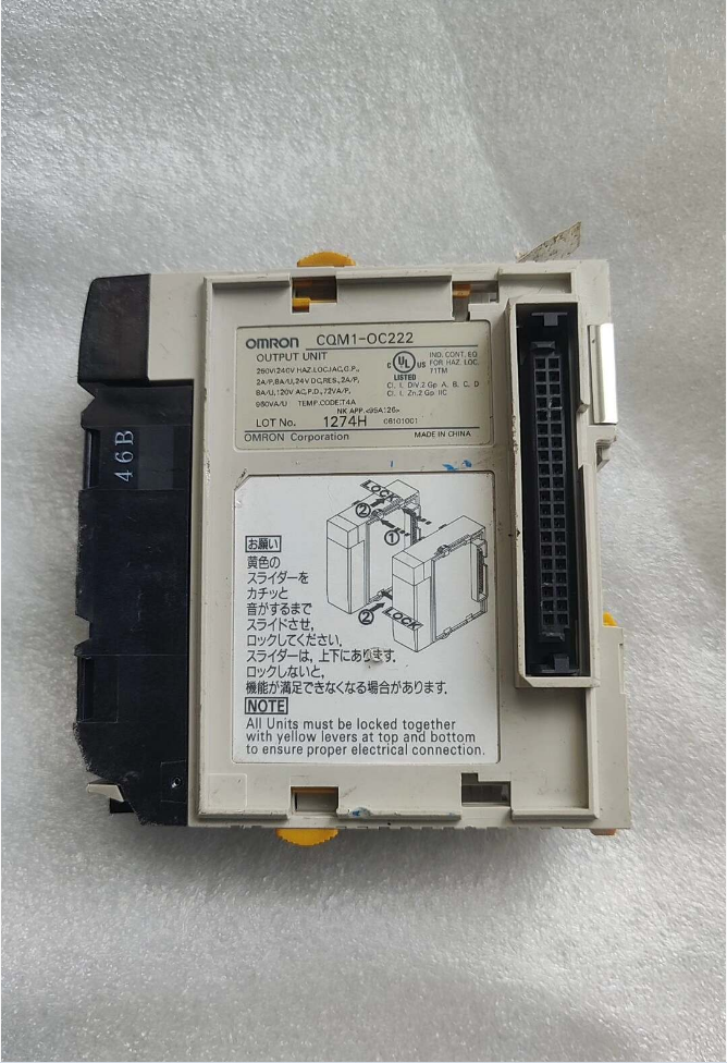

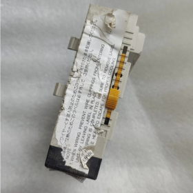
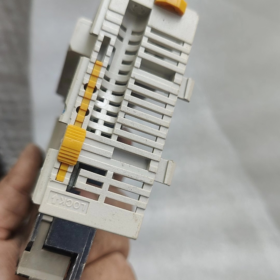
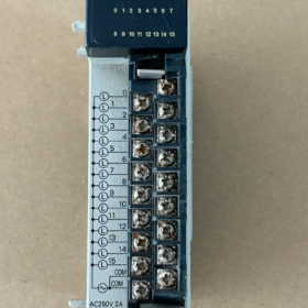
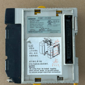
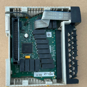
ОМРОН Инструкция по установке CQM1-OC222
⚠️Условие безопасности: Выполняйте все монтажные работы при полностью отключенном питании.. Выключите систему ПЛК и питание внешней нагрузки.. Горячая замена модулей запрещена.
Это блок ввода-вывода серии CQM1/CQM1H, который работает только со стойками объединительной платы CQM1H.. Несовместимо со стойками серии CJ или CP..
Ряд: CQM1 / Реле CQM1H модуль вывода, Устаревший, в наличии только подержанные или складские единицы.
Тип: Релейный контактный выход, 16 очки, 2 общие группы, 8 очков за группу (COM1: Очки 0-7; COM2: Очки 8-15).
Основные характеристики
| Элемент | Параметр |
| Количество точек вывода | 16-точечный релейный выход, 8 баллов за COM, 2 схемы |
| Напряжение нагрузки | 250 В переменного тока; 24 В постоянного тока |
| Ток за балл | 2A для резистивной нагрузки; 0.5A для индуктивной нагрузки |
| Макс. Текущий для каждой группы COM | 4А (всего за 8 очки); Макс. 8А для всего модуля |
| Выходной ответ | ВКЛ прибл.. 10 РС; ВЫКЛ прибл.. 10 РС (реле механической задержки) |
| Изоляция | Релейная оптоизоляция |
| Адрес | занимает 1 Канал ввода/вывода (16 кусочек) |
| Потребление тока объединительной платы | 5В постоянного тока: 130 мА |
| Терминалы | Винтовая клеммная колодка М3 |
>⚠️Уведомление: Все точки в одной группе COM должны использовать один и тот же внешний источник питания.. COM1 и COM2 могут использовать разное напряжение.. Независимая подача питания для каждой отдельной точки не допускается.. Это отличается от CQM1-OC221. (8-точечно-независимый COM).
Декодирование модели
CQM1: Модуль ввода-вывода ПЛК серии CQM1
ОК: Релейный контактный выход
222: 16 очки, 2 релейный выход общей группы
Сравнение с модулями аналогичных серий:
CQM1-OC221: 8 очки, независимая общая клемма для каждой точки, подходит для нагрузок с различным напряжением на канал
CQM1-OC222: 16 очки, 2 общие клеммы, более высокая плотность точек, общий источник питания внутри каждой группы
CQM1-OC224: Новая версия 8-точечного независимого COM-модуля
Рекомендации по подключению проводов
- COM1 подключается к общему для выходов внешнему источнику питания. 0-7; COM2 подключается к общему для выходов внешнему источнику питания. 8-15.
- Релейные выходы — сухие контакты.. Модуль не обеспечивает выходную мощность; внешнее питание должно подаваться на нагрузки.
- Для индуктивных нагрузок (катушки контактора), установить RC-демпферную цепь / Безынерционный диод для продления срока службы контактов реле.
- Момент затяжки клемм: 0.5 Н·м.
Варианты замены
Прямая совместимость с объединительной платой CQM1H (Прямая замена оборудования)
CQM1-OC222 снят с производства. Нет встроенного 16-канального релейного модуля 2-COM в той же серии..
Две части CQM1-OC221: Общий 16 очки, но большая площадь, 8-точечно-независимый COM.
Обновление до серии CJ (Несовместимость объединительной платы; Требуется полное обновление ПЛК)
CJ1W-OC211: 16-точечный релейный выход, 2 COM-группы (8 баллов за COM). Ближайший электрический эквивалент CQM1-OC222.. Логика программы портативна, но для него требуется объединительная плата CJ1/CJ2, и его нельзя подключить напрямую к стойке CQM1H..
Концепция внутренней замены
Замените весь ПЛК на Inovance H3U. / H5U, в паре с AM600-0016ER (16-точечный релейный выход, 2 общие клеммы).
Контрольный список проверки подержанного модуля для CQM1-OC222
- Визуальная проверка: Разъем объединительной платы без выгорания, клеммные колодки без дугового чернения, отсутствие коррозии на корпусе.
- Тест при включении: Вставка в стойку CQM1H; подтвердить, что модуль распознан без ошибок ввода-вывода.
- Принудительный вывод через программное обеспечение: Принудительно включите каждую точку с помощью CX-Programmer и наблюдайте за светодиодами панели.. Светодиод горит ≠ контакт исправен. (Исправный внутренний привод не гарантирует хорошие контакты реле., частая поломка подержанных агрегатов.)
- Измерение мультиметром: Измерьте непрерывность между выходной клеммой и соответствующим COM при принудительном включении.; проверьте бесконечное сопротивление в выключенном состоянии. Протестировать все 16 точки один за другим.
- Типичные виды отказов:
Светодиод горит, но нет непрерывности: Эрозия контактов реле (самая распространенная неисправность б/у)
Полный провал 8-балльной группы: Перегорание цепи COM из-за перегрузки по току
Индивидуально-точечное прилипание: Выход остается проводящим даже при команде ВЫКЛ.
Общие советы по устранению неполадок
- Механический срок службы реле ограничен.. Частое переключение индуктивной нагрузки ускоряет эрозию контактов., залипание и плохой контакт.
- Модуль не подает выходную мощность. Missing external load power may mimic “no output action”. Always check external power supply at COM terminals first.
- CQM1H CPUs all support CQM1-OC222. No CPU-version compatibility issue.
- Требования к среде установки
- Температура окружающей среды: 0 ~ 50 ℃. Ensure adequate ventilation inside control cabinet. Do not mount close to heaters or frequency converters.
- Влажность: 10%-85%относительной влажности, нет конденсата. Беречь от пыли, corrosive gas and oil mist.
- Avoid heavy vibration and strong electromagnetic interference sources (контакторы, high-power inverters).
- Mount horizontally; do not install upside-down.
- Mounting Modules on Rack (Unit Assembly)
- Confirm PLC system is fully powered off.
- Align the left-side backplane connector of CQM1-OC222 with the right-side backplane interface of preceding unit (Процессор, power supply or other I/O modules).
- Align modules and push horizontally until units fit tightly. Сдвиньте верхнюю и нижнюю защелки назад до упора, чтобы заблокировать соседние блоки и гарантировать надежный контакт объединительной платы..
- Установите торцевую крышку в дальнем правом конце всей системы и зафиксируйте ее защелки.. Отсутствие торцевой крышки приводит к сбоям распознавания ввода-вывода..
- Установите полную сборку ПЛК (источник питания + Процессор + Модули ввода-вывода) на рейку DIN35: Нажмите DIN-зажим на задней части модуля, чтобы зафиксировать его на рейке.. Освободите зажим для снятия.
Примечание: Положение физического слота определяет адрес канала ввода-вывода.. Нет DIP-переключателей на модуле; адреса автоматически назначаются в зависимости от местоположения слота.
- Удаление клеммного блока & Примерка (Съемный клеммный блок)
В CQM1-OC222 используется съемная клеммная колодка с винтом M3 для удобной автономной проводки и замены модуля без демонтажа полевых кабелей..
- Снимите клеммный блок: Зажмите обе боковые защелки и потяните прямо, пока модуль остается на стойке..
- После подключения, выровняйте и вставьте клеммную колодку обратно в слот, пока оба боковых зажима не защелкнутся в зафиксированном положении..
❗Не прилагайте усилий, чтобы не сломать зажим..
- Процедуры подключения & Технические характеристики
Терминальный крутящий момент
Винт М3, момент затяжки 0,45-0,5 Н·м. Чрезмерное затягивание повреждает резьбу; недостаточный крутящий момент создает риск термического ослабления соединения.
Размер проводника: 0.3-0.75 мм² (АВГ22-18). Используйте одножильный провод или многожильный провод с наконечниками.. Предотвращает возникновение коротких замыканий из-за случайных медных жил..
Логика подключения выходной цепи (Критический)
- Терминал COM1: Общий для баллов 0-7; Терминал COM2: Общий для баллов 8-15.
- Этот модуль имеет сухие контакты реле без внутреннего источника питания.. Подайте внешнее питание на клеммы COM и подключите нагрузку к клеммам выходных точек..
- COM1 и COM2 могут принимать разное напряжение. (например. одна группа AC220V, еще один DC24V). НЕ смешивайте переменный и постоянный ток в одной группе COM..
- Для индуктивных нагрузок (контакторы, электромагнитные клапаны): Примените RC-демпфер для нагрузок переменного тока.; обратно-параллельный безынерционный диод для нагрузок постоянного тока для защиты контактов реле.
Последовательность подключения
- Сначала просоедините цепи нагрузки возбуждения., затем подключите общий источник питания COM.
- Полная проводка, проверьте наличие коротких замыканий и оголенных медных жил.
- Убедитесь, что клеммная колодка полностью зафиксирована на модуле..
- Включение & Проверка оборудования
- Дважды проверьте, что питание ПЛК и питание внешней нагрузки отключены.; убедитесь, что правая торцевая крышка установлена.
- Включите питание системы ПЛК и включите ЦП.. Наблюдайте за индикаторами модуля:
В нормальном состоянии на этом модуле нет специального светодиода неисправности.. Светодиодные индикаторы выходов отражают состояние внутреннего выхода.
- Выход в Интернет через CX-Programmer. Убедитесь, что ЦП распознает блок ввода-вывода и не сообщает об ошибках модуля ввода-вывода..
- Принудительное включение/выключение каждой выходной точки в программном обеспечении.. Наблюдайте за состоянием светодиода и проверьте целостность клемм с помощью мультиметра для проверки выходов..
- Замена модуля & Процедура удаления (Обслуживание)
- Power off PLC and cut external load power.
- Pull out removable terminal block (field wiring may remain on terminal block without disassembly).
- Unlock locking latches between this module and adjacent units.
- Gently pull module outward to disengage backplane connector and release from DIN rail.
- Install new module following above installation steps and re-insert terminal block.
- Распространенные ошибки при установке & Resulting Faults
- Missing right-hand End Cover: CPU fails to detect module; I/O error reported.
- Locking latches not fully engaged: Плохой контакт объединительной платы; intermittent module dropout.
- Reversed COM-to-output-point wiring: Load inaction; mixed-voltage within one COM group → internal relay damage.
- Improper terminal screw torque: Overheating and arcing at terminals during operation.
- Hot-swap under power: Permanent burnout of backplane and module.
OMRON CQM1-OC222 Процедура диагностики неисправностей
Для блоков релейно-контактного вывода: Включение светодиода НЕ гарантирует исправность контактов реле.. Внутренняя цепь привода может работать нормально, пока контакты механического реле изношены или застряли. (отказ с высокой вероятностью).
Перед тестированием: Выключите ПЛК и отсоедините внешнее питание от клемм модуля, чтобы устранить помехи от внешней проводки..
- Визуальный осмотр (Состояние выключения)
- Разъем объединительной платы: Проверьте наличие следов ожогов, коррозия, погнутые или поврежденные штифты.
- Клеммы для подключения: Проверьте отсутствие почернения от дуги, следы ожогов или расплавленный пластик.
- Жилье: Проверьте наличие трещин, ожоги и запах горелого.
Следы ожогов или запах горелого обычно указывают на необратимое повреждение оборудования..
- Монтаж в стойке & Идентификационный тест программного обеспечения
Установите модуль в стойку CQM1/CQM1H с установленной торцевой крышкой.. Включите питание и подключите CX-Programmer..
- Убедитесь, что список оборудования правильно идентифицирует CQM1-OC222..
- Проверьте наличие ошибки модуля ввода-вывода / Аномальные сигналы тревоги устройства.
✅Нормальный: Правильная идентификация, нет тревог. Интерфейс объединительной платы, бортовые схемы питания и декодирования в основном работоспособны.
❌Неисправность: Модуль не обнаружен / сигнализация ошибки устройства:
Дважды проверьте торцевую крышку и запирающие защелки..
Тестовый модуль в альтернативном слоте; перекрестное тестирование с заведомо исправным модулем.
Если неисправность сохраняется: Повреждение встроенной материнской платы.
⚠️Успешное распознавание только подтверждает целостность печатной платы.. Это НЕ гарантирует исправность контактов реле.. Многие дефектные модули распознаются правильно, но имеют плохие контакты отдельных точек..
- Проверка светодиодного индикатора (Программный принудительный вывод)
Выйти в Интернет, принудительно включить/выключить выходы и наблюдать за светодиодами панели:
- Светодиод загорается при FORCE-ON и гаснет при FORCE-OFF..
Светодиод следует команде: Схема внутреннего управляющего транзистора работает.
светодиод не горит: Сбой внутренней цепи привода для этого канала.
Важный: Горящий светодиод означает, что внутренний диск активирован.. НЕ гарантирует проводимость контактов реле.! Измерение клеммы мультиметра обязательно..
- Проверка контактов реле мультиметром (Обязательный ключевой шаг)
Отсоедините всю внешнюю полевой проводку.. Установите мультиметр на звуковой сигнал непрерывности / режим сопротивления.
Сопоставление терминалов: COM1 для баллов 0-7; COM2 для баллов 8-15.
Этапы тестирования
- Принудительное включение точки в программном обеспечении: Измерьте сопротивление между выходной клеммой и соответствующей клеммой COM..
✅Нормальный: Почти нулевое сопротивление, звуковой сигнал непрерывности.
❌Неисправность: Бесконечное сопротивление / нет непрерывности → эрозия контактов реле (самая частая поломка).
- Принудительное отключение точки в программном обеспечении: Измерьте сопротивление между выходной клеммой и соответствующей клеммой COM..
✅Нормальный: Бесконечное сопротивление, нет преемственности.
❌Неисправность: Еще проводящий → Залипание контактов реле, неконтролируемая нагрузка (опасная неисправность).
Протестировать все 16 точки один за другим. Часто только 1-2 точки выходят из строя, в то время как другие остаются работоспособными.
Типичные проявления неисправностей
- Светодиод горит, но нет целостности клеммы: Эрозия контактов реле (топ б/у провал).
- Светодиод выключен, но клеммы остаются проводящими: Залипание контактов реле, выход не может быть отключен.
- Полный провал всех 8 баллы под один COM: Перегорание общей цепи COM из-за перегрузки по току.
- Прерывистое включение-выключение для отдельных точек: Окисленные контакты с нестабильной проводимостью..
- Отличие повреждения модуля от неисправности внешней проводки
Многие симптомы вызваны полевой проводкой, а не неисправностью модуля.. Следуйте этой последовательности проверок:
- Отсоедините клеммную колодку от полевых кабелей и отключите клеммы тестового модуля..
Неисправность сохраняется после удаления полевых кабелей → Аппаратный сбой модуля..
Все баллы проходят автономный тест; неисправности появляются только после повторного подключения полевых кабелей → Неисправность связана с внешней проводкой или нагрузкой/источником питания..
- Краткая сводная таблица неисправностей
| Феномен | Предполагаемое место неисправности |
| ПЛК вообще не может обнаружить модуль | Повреждение объединительной или материнской платы |
| Светодиод не выполняет команды программы | Повреждение внутренней цепи привода |
| Светодиод горит, но нет целостности клеммы | Эрозия контактов реле (высокочастотное повреждение) |
| Светодиод выключен, но клеммы остаются проводящими | Залипание контактов реле |
| Прерывистое действие для отдельных точек | Старение / окисленные контакты |
| Полный провал группы из 8 пунктов | Перегорание COM‑цепи |
Дополнительные замечания по применению
Реле CQM1-OC222 имеют ограниченный механический срок службы.. Частое переключение индуктивных нагрузок, таких как контакторы и электромагнитные клапаны, ускоряет износ контактов.. При покупке подержанных агрегатов, выполнить полную проверку целостности цепи мультиметром по 16 точкам. НЕ полагайтесь исключительно на состояние светодиодов или результат идентификации ПЛК..





NH42-63-318x560.png "Автоматические переключатели резерва типа PC CHINT (АТС)НХ42-63/4СЗ")



