 คอนแทคเตอร์,เบรกเกอร์,อินเวอร์เตอร์พลังงานแสงอาทิตย์,มิเตอร์ไฟฟ้า,แบตเตอรี่พลังงานแสงอาทิตย์

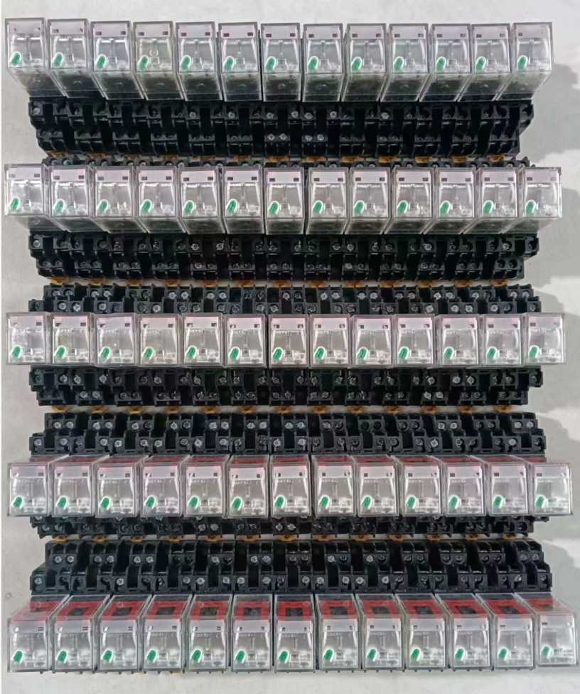

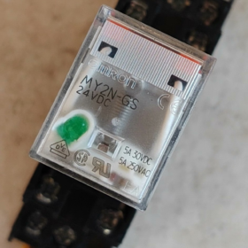
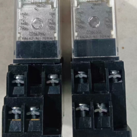
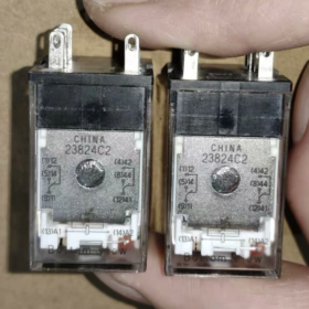
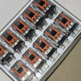
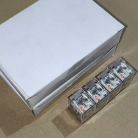
ที่ ออมรอน MY2N-GS AC220V เป็น 2 ขั้วแบบ double-throw (พปส) ปลั๊กอินขนาดเล็ก รีเลย์ระดับกลาง จากซีรีส์ OMRON MY-GS. เป็นการทดแทนที่ได้รับการอัปเกรดอย่างเป็นทางการสำหรับรุ่น Classic Legacy MY2N-J. การกำหนดค่ามาตรฐานมีไฟแสดงการทำงาน LED, ตัวบ่งชี้สถานะทางกลและคันโยกล็อคทดสอบด้วยตนเอง. ใช้หน้าสัมผัสโลหะผสมเงิน, มันมีความน่าเชื่อถือสูง, อายุการใช้งานยาวนานและการเดินสายไฟที่สะดวก. ส่วนใหญ่ใช้สำหรับการขยายสัญญาณเอาต์พุต PLC, การสลับโหลดและการแปลงลอจิกวงจร, เป็นส่วนประกอบพื้นฐานที่เป็นสากลสำหรับตู้ควบคุมระบบอัตโนมัติทางอุตสาหกรรม.
- รายละเอียดรหัสรุ่น
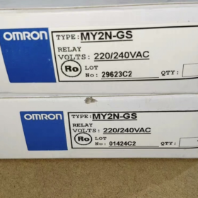
รุ่นมาตรฐานเต็มรูปแบบ: MY2N-GS AC220/240V
ของฉัน: ชุดผลิตภัณฑ์, รีเลย์ระดับกลางกำลังขนาดเล็กอเนกประสงค์
2: จำนวนชุดผู้ติดต่อ, 2 ชุดผู้ติดต่อการเปลี่ยนแปลง (พปส, 2 เปิดตามปกติ + 2 ปกติปิด)
เอ็น: ขั้วต่อปลั๊กอินมาตรฐานพร้อมไฟแสดงการทำงานในตัว
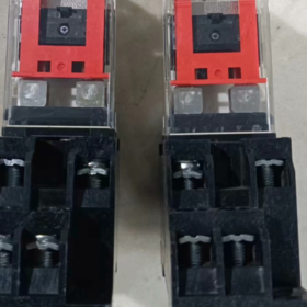
จีเอส: ซีรีส์รุ่นต่อไป (มาตรฐานการสร้าง). มาแทนที่ซีรีส์ MY2N-J ดั้งเดิม, มีคันโยกล็อคเพิ่มเติม, และมอบความทนทานต่อการสัมผัสและประสิทธิภาพทางไฟฟ้าที่เหมาะสมที่สุด.
ไฟ AC220/240V: จัดอันดับแรงดันไฟฟ้าคอยล์, ไฟฟ้ากระแสสลับ 220~240V, เข้ากันได้กับแหล่งจ่ายไฟ 50/60Hz.
หมายเหตุเพิ่มเติม
ผลิตภัณฑ์ส่วนใหญ่ที่มีจำหน่ายในท้องตลาดจะติดตั้งคันโยกล็อคตามค่าเริ่มต้น (คำต่อท้าย -R), รองรับการทดสอบด้วยตนเองและการล็อคหน้าสัมผัส.
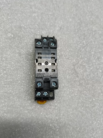
ตรงกับซ็อกเก็ต 8 พินมาตรฐาน: ขั้วต่อแบบสกรู PYF08A, เทอร์มินอลแบบกดเข้าประเภท PYF08A-PU.
- ข้อมูลจำเพาะทางเทคนิคหลัก
| หมวดหมู่ | ข้อมูลจำเพาะ |
| การกำหนดค่าการติดต่อ | 2 ชุดผู้ติดต่อการเปลี่ยนแปลง (พปส, 2โน+2เอ็นซี) |
| จัดอันดับการติดต่อปัจจุบัน | 5ก (โหลดตัวต้านทาน AC250V); 5ก (โหลดตัวต้านทาน DC30V) |
| ติดต่อวัสดุ | โลหะผสมเงิน (AgSnO₂) |
| จัดอันดับแรงดันไฟฟ้าคอยล์ | ไฟฟ้ากระแสสลับ 220~240V, 50/60เฮิรตซ์ |
| การใช้พลังงานคอยล์ | ประมาณ. 1.2~1.5 วีเอ |
| เวลาดำเนินการ | ≤ 20 นางสาว |
| เวลาวางจำหน่าย | ≤ 20 นางสาว |
| ชีวิตเครื่องกล | ≥ 50 ล้านการดำเนินงาน |
| ชีวิตไฟฟ้า | ≥ 100,000 การดำเนินงาน (ภายใต้โหลดความต้านทานที่กำหนด) |
| อิเล็กทริกทนต่อแรงดันไฟฟ้า | 2กิโลโวลต์ เอซี / 1นาที (ระหว่างคอยล์และหน้าสัมผัส) |
| บ่งชี้สถานะ | ไฟ LED สีแดง (สว่างขึ้นเมื่อมีพลังงาน) + คันโยกตัวบ่งชี้ทางกล |
| ประเภทการติดตั้ง | ประเภทปลั๊กอิน, ใช้กับเต้ารับมาตรฐานที่ตรงกัน |
| จำนวนพิน | 8 หมุด |
| อุณหภูมิแวดล้อมในการทำงาน | -40℃ ~ +70 ℃ (ไม่มีการควบแน่น) |
| การป้องกันทางเข้า | IP40 (ตัวรีเลย์) |
| การรับรอง | ซีอี, แอล, ซีเอสเอ, วีดีอี, ซีคิวซี |
- รายชื่อรุ่นเต็มของซีรีส์เดียวกัน
4.1 จำแนกตามชุดการติดต่อ
| ชุดการติดต่อ | จำนวนพิน | รุ่นมาตรฐาน | รุ่นมีก้านล็อค | จัดอันดับการติดต่อปัจจุบัน |
| 2 ผู้ติดต่อที่เปลี่ยนแปลง (2โน+2เอ็นซี) | 8 หมุด | MY2N-GS | MY2N-GS-R | 5ก |
| 4 ผู้ติดต่อที่เปลี่ยนแปลง (4โน+4เอ็นซี) | 14 หมุด | MY4N-GS | MY4N-GS-R | 5ก |
4.2 พิกัดแรงดันไฟฟ้าคอยล์ทั่วไป
ทั้งซีรีย์รองรับแรงดันไฟฟ้ามาตรฐานต่อไปนี้, โดดเด่นด้วยส่วนต่อท้ายแรงดันไฟฟ้าเท่านั้น:
ดี.ซี: ดีซี12วี, ดีซี24วี, ดีซี48วี
เครื่องปรับอากาศ: เอซี24วี, AC110/120V, ไฟ AC200/220V, ไฟ AC220/240V
- การกำหนดพิน & คำแนะนำในการเดินสายไฟ
5.1 คำจำกัดความของพิน (มุมมองด้านบนจากด้านสายไฟของเต้ารับ)
| หมายเลขพิน. | การทำงาน | คำอธิบาย |
| 13 (A1) | ปลายด้านหนึ่งของคอยล์ | เชื่อมต่อกับสายไฟ AC220V |
| 14 (A2) | ปลายอีกด้านของคอยล์ | เชื่อมต่อกับสายไฟที่เป็นกลาง AC220V |
| 9 | เทอร์มินัลทั่วไป 1 (คอม1) | พินทั่วไปสำหรับชุดหน้าสัมผัสที่ 1 |
| 1 | ปกติปิด 1 (เอ็นซี1) | ดำเนินการกับพิน 9 เมื่อคอยล์หมดพลังงาน |
| 5 | เปิดตามปกติ 1 (หมายเลข 1) | ดำเนินการกับพิน 9 เมื่อคอยล์ได้รับพลังงาน |
| 12 | เทอร์มินัลทั่วไป 2 (คอม2) | พินทั่วไปสำหรับชุดหน้าสัมผัสที่ 2 |
| 4 | ปกติปิด 2 (เอ็นซี2) | ดำเนินการกับพิน 12 เมื่อคอยล์หมดพลังงาน |
| 8 | เปิดตามปกติ 2 (NO2) | ดำเนินการกับพิน 12 เมื่อคอยล์ได้รับพลังงาน |
5.2 ข้อควรระวังในการเดินสายไฟ
- คอยล์ AC ไม่มีข้อกำหนดเรื่องขั้ว. A1 และ A2 สามารถเชื่อมต่อกับสายไฟที่มีกระแสไฟฟ้าและสายนิวทรัลได้โดยพลการ.
- สำหรับโหลดอุปนัย (คอนแทคเตอร์, โซลินอยด์วาล์ว), ขอแนะนำให้เชื่อมต่อเครื่องป้องกันไฟกระชาก (วงจร Snubber RC) ควบคู่ไปกับการยืดอายุการใช้งานหน้าสัมผัส.
- อย่าทำงานเกินกว่ากระแสไฟที่กำหนด. ใช้คอนแทคเตอร์สำหรับการสลับรองของโหลดกำลังสูง.
- คันโยกล็อคสามารถปิดหน้าสัมผัสได้ด้วยตนเอง, ซึ่งใช้ในการทดสอบการเดินเครื่องและการตรวจสอบวงจร.
- การใช้งานทั่วไป
ขยายสัญญาณเอาท์พุต PLC เพื่อขับเคลื่อนโหลด เช่น โซลินอยด์วาล์ว, คอนแทคเตอร์และไฟแสดงสถานะ
การแปลงลอจิกวงจร, การจับคู่ระดับและการแยกสัญญาณภายในตู้ควบคุม
การควบคุมการเริ่ม-หยุด, รีเลย์สัญญาณและการขยายวงจรสำหรับอุปกรณ์อัตโนมัติ
การควบคุมวงจรทุติยภูมิและการส่งสัญญาณการป้องกันในระบบจำหน่ายไฟฟ้า
- เมทริกซ์การแก้ไขปัญหาทั่วไป
| ปรากฏการณ์ความผิดปกติ | สาเหตุที่แท้จริง | โซลูชั่นทีละขั้นตอน |
| รีเลย์ไม่ทำงานและไฟแสดงสถานะจะดับลงหลังจากเปิดเครื่อง | 1. แรงดันไฟจ่ายผิดปกติ / สายไฟหัก | 1. วัดแรงดันไฟฟ้าระหว่าง A1 และ A2 เพื่อยืนยันการจ่ายไฟ AC220V ปกติ |
| 2. คอยล์เปิดที่ถูกเผาไหม้ | 2. ทดสอบความต้านทานของคอยล์; เปลี่ยนรีเลย์หากตรวจพบวงจรเปิด | |
| 3. การสัมผัสกับซ็อกเก็ตไม่ดี | 3. ใส่รีเลย์กลับเข้าไปใหม่และทำความสะอาดพินของซ็อกเก็ต | |
| ไฟแสดงสถานะสว่างขึ้นแต่หน้าสัมผัสไม่มีเอาต์พุต | 1. หน้าสัมผัสแบบเชื่อมหรือออกซิไดซ์ที่มีการนำไฟฟ้าไม่ดี | 1. ทดสอบความต่อเนื่องของการสัมผัส; เปลี่ยนรีเลย์หากหน้าสัมผัสเสียหาย |
| 2. สายไฟขาดที่ด้านโหลด | 2. ตรวจสอบสายไฟและความสมบูรณ์ของวงจรโหลด | |
| 3. หน้าสัมผัสเสียหายเนื่องจากการโอเวอร์โหลด | 3. ตรวจสอบกระแสโหลด; เลือกรุ่นที่ได้รับการจัดอันดับสูงกว่าสำหรับสภาวะโอเวอร์โหลด | |
| ผู้ติดต่อไม่สามารถปล่อยและติดกันหลังจากปิดเครื่อง | 1. การเชื่อมแบบสัมผัสที่เกิดจากอาร์คไฟฟ้าภายใต้กระแสไฟฟ้าแรงสูง | 1. เปลี่ยนรีเลย์และติดตั้งส่วนประกอบป้องกันไฟกระชาก |
| 2. กลไกติดขัดหรือสปริงส่งคืนล้มเหลว | 2. ตรวจสอบกลไกภายใน; เปลี่ยนรีเลย์ทั้งหมดหากเกิดการติดขัดทางกลไก | |
| เสียงหึ่งผิดปกติระหว่างการทำงาน | 1. การดึงดูดกระดองไม่สมบูรณ์เนื่องจากแรงดันไฟฟ้าต่ำ | 1. ปรับแรงดันไฟฟ้าให้เป็นช่วงที่กำหนด |
| 2. น้ำมันหรือฝุ่นบนพื้นผิวแกนกลาง | 2. เปลี่ยนรีเลย์; อย่าแยกชิ้นส่วนแกนด้วยตนเอง | |
| ความร้อนมากเกินไปหรือการเหนื่อยหน่ายของคอยล์ | 1. แหล่งจ่ายไฟแรงดันเกิน | 1. ตรวจสอบให้แน่ใจว่าแรงดันไฟจ่ายเป็นไปตามค่าพิกัด; ห้ามใช้งานแรงดันไฟฟ้าเกิน |
| 2. การสลับความถี่สูงในระยะยาว | 2. ลดความถี่ในการสลับหรือใช้โซลิดสเตตรีเลย์ |
- การอ้างอิงแบบจำลองทางเลือก
การเปลี่ยนมรดกของแบรนด์เดิม: MY2N-J AC220V (รองรับพินอย่างสมบูรณ์, โดยไม่ต้องล็อคคันโยก)
ทางเลือกภายในประเทศ: ตู้ NJX-13FW/2Z AC220V, เดลิซี่ CDZ9-52P AC220V
นำเข้าเทียบเท่า: ชไนเดอร์ RXM2LB2P7, เอบีบี CR-MX230AC2L, ฟีนิกซ์ติดต่อ REL-MR-230AC/21
เมทริกซ์การแก้ไขปัญหาสำหรับรีเลย์ OMRON MY2N-GS AC220V 5A
คุณสมบัติรุ่นนี้ 2 ชุดผู้ติดต่อการเปลี่ยนแปลง, 8-โครงสร้างปลั๊กอินพิน, ไฟ LED แสดงการทำงานและคันโยกล็อค. ด้านล่างนี้คือคำแนะนำในการแก้ไขปัญหาโดยจัดเรียงตามลำดับการตรวจสอบ ณ สถานที่ปฏิบัติงาน (จากง่ายไปซับซ้อน), ครอบคลุมข้อบกพร่องที่เกิดจากไฟฟ้า, ปัญหาทางกลและการติดตั้ง.
| ปรากฏการณ์ความผิดปกติ | สาเหตุที่แท้จริง | โซลูชั่นทีละขั้นตอน |
| ไม่มีการใช้งานและไฟ LED สีแดงดับลงหลังจากเปิดเครื่อง | 1. ความผิดปกติในวงจรไฟฟ้าภายนอก: ไม่มีแรงดันไฟฟ้า, สายไฟหลวม, สายไฟที่มีกระแสไฟฟ้า/เป็นกลางขาด | 1. วัดแรงดันไฟฟ้ากระแสสลับระหว่างพินซ็อกเก็ต 13(A1) และพิน 14(A2). ยืนยันแรงดันไฟฟ้าภายใน AC220V ± 10%. ตรวจสอบสวิตช์อัปสตรีมและขั้วต่อหากตรวจไม่พบแรงดันไฟฟ้า. |
| 2. หน้าสัมผัสซ็อกเก็ตไม่ดี: หมุดออกซิไดซ์หรือการเชื่อมต่อหลวมระหว่างรีเลย์และซ็อกเก็ต | 2. ตัดไฟ, ดึงรีเลย์ออก, ทำความสะอาดออกไซด์บนหมุดและขั้วต่อซ็อกเก็ต, จากนั้นใส่กลับเข้าไปใหม่ให้แน่น. | |
| 3. คอยล์เปิดที่ถูกเผาไหม้: พังทลายของแรงดันไฟฟ้าเกิน, อายุของฉนวนหรือผลกระทบจากไฟกระชาก | 3. วัดความต้านทานของคอยล์. ความต้านทานปกติจะอยู่ที่ประมาณ. 12~15kΩ ที่ 25℃. เปลี่ยนรีเลย์หากวงจรเปิดหรือมีความต้านทานผิดปกติเกิดขึ้น. | |
| 4. คันโยกล็อคติดอยู่ที่ตำแหน่งปลดล็อค (สำหรับเวอร์ชัน -R) | 4. รีเซ็ตคันโยกล็อคด้านบนไปที่ตำแหน่งปกติเพื่อขจัดปัญหากลไกติดขัด. | |
| ไฟ LED สว่างขึ้นแต่หน้าสัมผัสไม่มีเอาต์พุต | 1. การเดินสายไฟผิดสำหรับวงจรหน้าสัมผัส: การเชื่อมต่อแบบผสมของทั่วไป, ขั้วต่อ NO และ NC | 1. ตรวจสอบคำจำกัดความของพิน: ขั้วต่อ COM คือพิน 9 และพิน 12; ไม่มีขั้วเป็นพิน 5 และพิน 8. ตรวจสอบให้แน่ใจว่าไม่มีการเชื่อมต่อกับพิน NC ผิด. |
| 2. วงจรโหลดเสียหาย: ไม่มีกระแสไฟสำหรับโหลดหรือขั้วต่อหลวม | 2. กดคันโยกล็อคเพื่อปิดหน้าสัมผัสด้วยตนเองและทดสอบความต่อเนื่อง. ถ้ายังเปิดอยู่, ตรวจสอบกำลังและสายไฟด้านโหลด. | |
| 3. หน้าสัมผัสที่ถูกเผาไหม้หรือออกซิไดซ์ที่เกิดจากการโอเวอร์โหลดในระยะยาวและอาร์กไฟฟ้า | 3. เปลี่ยนรีเลย์หากหน้าสัมผัสยังคงเปิดอยู่เนื่องจากความเหนื่อยหน่ายหรือการเกิดออกซิเดชันหลังจากปิดด้วยตนเอง. | |
| 4. กลไกภายในติดขัด: คอยล์ดึงเข้าตามปกติ แต่การเชื่อมต่อล้มเหลวในการขับเคลื่อนหน้าสัมผัส | 4. เปลี่ยนรีเลย์หากพบว่ากลไกติดขัดระหว่างการทำงานแบบแมนนวล. | |
| รายชื่อปิดอยู่และไม่สามารถปล่อยออกมาได้หลังจากปิดเครื่อง | 1. ติดต่อเชื่อม: เกิดจากการโอเวอร์โหลด, ไฟฟ้าลัดวงจรหรืออาร์คไฟฟ้าโดยไม่มีระบบป้องกันไฟกระชากสำหรับโหลดแบบเหนี่ยวนำ | 1. ตัดไฟและยืนยันว่าไม่มีแรงดันไฟฟ้าที่คอยล์. รีเซ็ตคันล็อคและตรวจสอบว่าผู้ติดต่อเปิดอยู่หรือไม่. |
| 2. สปริงส่งคืนล้มเหลว: การลดทอนความยืดหยุ่นเนื่องจากการสลับบ่อยครั้งและอุณหภูมิสูง | 2. เปลี่ยนรีเลย์ทันทีหากหน้าสัมผัสยังคงปิดอยู่หลังจากรีเซ็ต. หน้าสัมผัสแบบเชื่อมไม่สามารถซ่อมแซมเพื่อนำกลับมาใช้ใหม่ได้. | |
| 3. สิ่งแปลกปลอมติดขัด: ฝุ่นหรือเศษเหล็กติดอยู่ภายในกระดองหรือกลไกการสัมผัส | 3. ตรวจสอบให้แน่ใจว่ากระแสโหลดไม่เกิน 5A. ติดตั้งเครื่องป้องกันไฟกระชาก RC สำหรับโหลดแบบเหนี่ยวนำ. | |
| 4. การล็อคคันโยกล็อคโดยไม่ได้ตั้งใจหลังการทดสอบด้วยตนเอง | 4. ทำความสะอาดฝุ่นและเศษเหล็กโดยรอบ; เปลี่ยนรีเลย์หากไม่สามารถแก้ไขปัญหาการติดขัดของกลไกได้. | |
| เสียงหึ่งผิดปกติระหว่างการทำงาน | 1. แรงดันไฟฟ้าที่จ่ายต่ำทำให้เกิดการดึงดูดแกนกลางที่ไม่สมบูรณ์และการสั่นสะเทือนของกระดอง | 1. วัดแรงดันคอยล์และเก็บไว้ภายใน AC220V±10%. ตรวจสอบแรงดันไฟฟ้าตกในวงจรไฟฟ้าหากแรงดันไฟฟ้าต่ำ. |
| 2. น้ำมัน, ฝุ่นหรือสนิมบนพื้นผิวแกนทำให้เกิดช่องว่างแม่เหล็กมากเกินไป | 2. ใส่รีเลย์กลับเข้าไปจนสุดแล้วขันสกรูยึดของซ็อกเก็ตและรางให้แน่น. | |
| 3. วงแหวนลัดวงจรที่แกนเสียหาย (ข้อผิดพลาดเฉพาะของคอยล์ AC) | 3. เปลี่ยนรีเลย์หากยังมีเสียงรบกวนอยู่หลังจากทำความสะอาดพื้นผิวแกนกลาง (แหวนลัดวงจรเสียหายหรือแกนสึกหรอ). | |
| 4. ทรงหลวมระหว่างรีเลย์, ซ็อกเก็ตและราง DIN ทำให้เกิดเสียงสะท้อน | 4. ปรับตำแหน่งการติดตั้งเพื่อลดช่องว่างของเสียงสะท้อน. | |
| ความร้อนมากเกินไปหรือความเหนื่อยหน่ายของคอยล์ดำ | 1. แรงดันไฟฟ้าเกินอย่างรุนแรงเกินขีดจำกัดบน AC240V ส่งผลให้คอยล์โอเวอร์โหลด | 1. ตรวจสอบแรงดันไฟฟ้าอย่างเคร่งครัด; ห้ามใช้งานแรงดันไฟฟ้าเกินในระยะยาว. |
| 2. ความถี่ในการสลับสูงเกินไปทำให้เกิดความร้อนสูงเกินไปสะสมเกินขีดจำกัดฉนวนคลาส B | 2. จำกัดความถี่ในการสลับ ≤ 20 ครั้งต่อนาที. ใช้โซลิดสเตตรีเลย์สำหรับสภาพการทำงานที่มีความถี่สูง. | |
| 3. การกระจายความร้อนที่ไม่ดีภายใต้อุณหภูมิแวดล้อมที่สูงจะช่วยเร่งการเสื่อมสภาพของฉนวน | 3. ปรับปรุงการกระจายความร้อนภายในตู้. เก็บให้ห่างจากส่วนประกอบที่สร้างความร้อน เช่น อินเวอร์เตอร์และคอนแทคเตอร์. อุณหภูมิแวดล้อมต้องไม่เกิน 70 ℃. | |
| 4. การพังทลายของฉนวนที่เกิดจากแรงดันไฟเกินและไฟกระชาก | 4. เชื่อมต่อเครื่องป้องกันไฟกระชาก RC แบบขนานกับคอยล์เพื่อลดแรงดันไฟเกินชั่วคราวระหว่างการปิดเครื่อง. | |
| การติดต่อไม่ดี, สัญญาณไม่ต่อเนื่อง | 1. ออกซิเดชันและฝุ่นบนพื้นผิวสัมผัสทำให้เกิดความต้านทานต่อการสัมผัสสูง | 1. ตัดไฟ, ดึงรีเลย์ออก, ทำความสะอาดออกไซด์บนหน้าสัมผัสและหมุด, แล้วใส่ให้แน่น. |
| 2. กระแสโหลดต่ำเกินไปไม่สามารถทะลุชั้นออกไซด์ได้ (วงจรสัญญาณระดับต่ำ) | 2. ใช้รีเลย์หน้าสัมผัสเคลือบทองหรือเพิ่มกระแสไฟในวงจรอย่างเหมาะสมสำหรับการใช้งานสัญญาณระดับต่ำ. | |
| 3. ความล้าหรือการเกิดออกซิเดชันของหมุดซ็อกเก็ตทำให้การเชื่อมต่อหลวม | 3. เปลี่ยนช่องเสียบ PYF08A ที่ตรงกัน หากพินสูญเสียความยืดหยุ่นหรือถูกออกซิไดซ์อย่างรุนแรง. | |
| 4. Incomplete insertion of relay leading to mechanical intermittent contact | 4. Replace with a new relay if intermittent fault occurs frequently to prevent repeated oxidation. | |
| Abnormal brightness or flickering of indicator | 1. Unstable power supply with large voltage fluctuation | 1. Measure coil voltage and confirm stable power supply without severe fluctuation. |
| 2. Poor socket contact leading to intermittent coil power supply | 2. Reinsert the relay and clean pins to eliminate loose contact. | |
| 3. Aging and failure of current-limiting resistor for indicator | 3. Measure coil resistance if indicator malfunctions under stable voltage. Replace the relay immediately if inter-turn short circuit (ความต้านทานต่ำ) is detected. | |
| 4. Coil inter-turn short circuit causing abnormal voltage division | 4. Temporary use is allowed if only indicator fails while contacts work normally. แนะนำให้เปลี่ยนแบตช์. |
หมายเหตุการแก้ไขปัญหาเพิ่มเติม
- ลำดับความสำคัญในการตรวจสอบ: ปฏิบัติตามลำดับ: แหล่งจ่ายไฟภายนอก → หน้าสัมผัสซ็อกเก็ต → ตัวรีเลย์. 80% ข้อผิดพลาดเกิดจากปัญหาสายไฟและปลั๊กไฟ. จัดลำดับความสำคัญของการตรวจสอบเหล่านี้เพื่อหลีกเลี่ยงการเปลี่ยนโดยไม่จำเป็น.
- กฎระเบียบด้านความปลอดภัย: ปฏิบัติตามมาตรฐานความปลอดภัยทางไฟฟ้าในระหว่างการทดสอบจริง. ตัดไฟก่อนตรวจสอบหน้าสัมผัสและคอยล์ เพื่อป้องกันไฟฟ้าช็อตและไฟฟ้าลัดวงจร.
- การอ้างอิงอายุการใช้งาน: อายุการใช้งานไฟฟ้าที่ได้รับการจัดอันดับคือ 100,000 การทำงานภายใต้โหลดความต้านทาน. อายุการใช้งานจะลดลงมากกว่า 50% สำหรับโหลดอุปนัย. แนะนำให้เปลี่ยนใหม่เป็นประจำเมื่อถึงขีดจำกัดการบริการ.


")


NH42-63-318x560.png "สวิตช์ถ่ายโอนอัตโนมัติชนิด CHINT PC (เอทีเอส)NH42-63/4SZ")


