 Contactor,circuit breaker,solar inverter,electric meter,solar batteries

(Varispeed P7 Inverter Specialized for Fans & Pumps)
- Model Code Breakdown
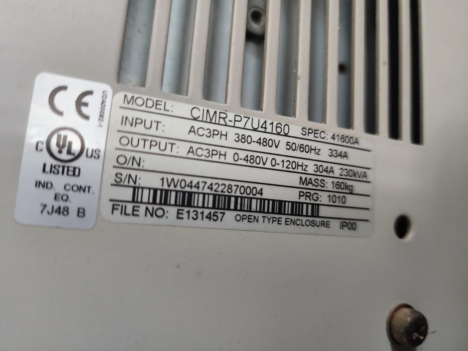
CIMR-P7U4160 (Full name on nameplate: CIMR-P7U41600 PDF)
CIMR: Universal prefix for Yaskawa inverters
P7: P7 series, energy-saving V/F inverter dedicated to fans and pumps
U: 400V three-phase high-voltage model (380~480V)
4160: Power rating code, corresponding to 250HP / 160kW class
- Core Electrical Rated Specifications
2.1 Main Circuit Power Ratings
| Item | Value |
| Input Specification | 3-phase AC 380~480V, 50/60Hz |
| Rated Input Current | 334 A |
| Rated Output Capacity | 230 kVA |
| Rated Output Current | 304 A (ND Normal Duty) |
| Matching Motor Power | 250HP / 160kW 3-phase induction motor |
| Max Output Voltage | 3-phase 0 ~ input voltage (max. 480V) |
| Maximum Output Frequency | 120 Hz |
| Carrier Frequency | Adjustable from 2kHz to 10kHz |
| Accel/Decel Time Range | 0.0~6000s, two independent accel/decel groups |
2.2 Allowable Power Supply Fluctuation
Voltage: +10% / -15%
Frequency: ±5%
2.3 Control Performance
Speed Adjustment Range: 40:1 (V/F control)
Speed Control Accuracy: ±2%~±3%
Control Modes: Standard V/F, Energy-saving Square V/F (for fans & pumps), Multi-point V/F curve
- Mechanical & Environmental Specifications
- Enclosure Rating: NEMA1 wall-mounted closed cabinet
- Overall Weight: Approx. 170kg
- Operating Ambient Temperature: 0℃ ~ +40℃ (derating required above 40℃)
- Humidity: ≤80%RH, no condensation
- Altitude: No derating below 1000m; derate 1% per additional 100m above 1000m
- Cooling Method: Built-in high-power cooling fan (individually replaceable)
- Braking Mode: Built-in DC dynamic braking; external braking unit/resistor required for high-power regenerative energy
- Hardware Interface Configuration
4.1 Main Circuit Terminals (R/S/T Input; U/V/W Motor Terminals; +/Braking Unit; PE Earth)
R, S, T: 3-phase 380~480V power input
U, V, W: Connection to 3-phase induction motor
+, -: External braking resistor / regenerative unit connection
PE: Protective earth (common ground for cabinet and main circuit)
4.2 Standard Control Circuit Configuration
Digital Inputs: 8 channels, switchable between NPN and PNP
Digital Relay Outputs: 2 normally open contacts (fault signal, run status signal)
Analog Inputs: 2 channels (0~10V / 4~20mA frequency reference)
Analog Outputs: 2 channels (monitor frequency, current, voltage)
Communication: Standard Modbus-RTU; optional Profibus & DeviceNet communication cards
Digital Operator: 5-line 16-character LCD, supports parameter upload, download and copy
- Typical Application Scenarios
The P7 series is designed specifically for square-torque loads. The high-power CIMR-P7U4160 model applies to:
- Large cooling water circulation pumps, municipal water supply booster pumps
- Factory centrifugal fans, boiler induced draft fans, main dust removal fans
- Central air-conditioning chiller units, large cooling tower water pumps
- Mining & metallurgy dust exhaust fans, wastewater treatment aeration pumps
Advantages: Built-in energy-saving square torque curve, sleep function, multi-pump rotation switching, constant pressure PID control
- Discontinued Replacement Solution (P7 series fully discontinued)
Direct Drop-in Upgrade: Yaskawa P1000 Series
Equivalent replacement model: CIMR-PU4A0415ABA
- Fully matched power rating: 304A output, compatible with 160kW motors
- Full function coverage: Retains all fan & pump dedicated functions of P7 (multi-pump control, PID, sleep mode)
- Highly compatible communication protocols, terminal logic and parameter sets, low renovation workload
- Merits: Higher energy efficiency, built-in EMC filter, enhanced fault diagnosis, abundant spare parts
Alternative General Heavy-Duty Option: A1000 Series
(Vector type, selected for heavy-duty or closed-loop control demands)
- Common Fault Codes & Troubleshooting Matrix (Universal for P7 Series)
| Fault Code | Fault Description | Root Cause | Remedial Actions |
| OC/OC1/OC2/OC3 | Overcurrent during Accel / Decel / Constant Speed | Motor short circuit, cable earth fault, mechanical stall, overly short accel/decel time | Test motor insulation; extend accel/decel time; inspect mechanical jamming |
| GF | Output Ground Fault | Damaged insulation on U/V/W cables, motor winding breakdown to earth | Disconnect motor cables section by section and test insulation separately |
| UV | DC Bus Undervoltage | Mains phase loss, excessive voltage drop, poor contact of contactor | Measure three-phase voltage of R/S/T; fasten main circuit terminals |
| OV | DC Bus Overvoltage | Excessively fast deceleration, no braking resistor, high mains voltage | Lengthen deceleration time; install external braking unit |
| OL1 | Motor Overload | Excessive load, long-time low-speed operation, incorrect motor current parameter | Verify rated motor current parameter E2-01; reduce load |
| OL2 | Inverter Overload | Sustained 150% rated current for 1 minute | Reduce load, upgrade inverter size, lower carrier frequency |
| SPI | Input Phase Loss | Broken wire on one R/S/T phase, blown fuse | Inspect input circuit breaker, terminals and three-phase voltage balance |
| SPO | Output Phase Loss | Disconnection of one U/V/W phase, burnt single-phase motor contact | Tighten motor terminals; test cable continuity |
| OH1/OH2 | Overheat (Heat Sink) | Dust-clogged air duct, damaged cooling fan, ambient temperature over 40℃ | Clean air filter; replace cooling fan; improve ventilation |
| LF | Output Three-Phase Imbalance | Damaged motor winding, loose wiring terminals | Measure three-phase output current; fasten all terminals |
- Strict Wiring & Installation Prohibitions
- Main power cables and control signal wires must be routed in separate cable trays with a minimum spacing of 30cm; long parallel laying is forbidden.
- Shielded motor cables are recommended; shield shall be grounded only at the control cabinet end.
- Main circuit copper busbars of high-power models shall be tinned and tightened with specified torque to avoid overheating and arcing.
- For multi-pump linked systems, AC contactors shall not be installed on the inverter output side for frequent switching.
- For sites with heavy dust and moisture, clean air duct filters regularly to prevent overheat alarms.
- If long motor cables (>50m) are required, an output du/dt filter must be installed to suppress peak voltage and protect motor insulation.
- Key Basic Commissioning Parameters (Standard for Fan & Pump Applications)
- E1-06 Base Frequency: Rated 50/60Hz as marked on motor nameplate
- E1-13 Square V/F (Fan Energy Saving): Set to 2 to enable square torque curve
- b5 PID Pressure Closed-Loop: Set target pressure and P/I/D gains
- b5-17 Sleep Function: Low-frequency energy-saving sleep, auto-stop during idle periods
- C1-01~C1-04 Accel & Decel Time: ≥15s recommended for pumps, ≥30s for fans to avoid overcurrent
- E2-01 Motor Rated Current: Enter value per motor nameplate, baseline for overload protection
Complete Model List of Yaskawa Varispeed P7 Series (CIMR-P7U□4□□□) 400V Series
Notes
- Series Naming Rule: `CIMR-P7U4XXX0`. The full code printed on the nameplate ends with digit 0, which is omitted as the short model number for selection (e.g., CIMR-P7U4160).
- U = Dedicated 3-phase 380~480V model for fans and pumps; ND Normal Duty (square-torque loads for fans & pumps).
- Power correspondence unit: kW / HP / Rated Output Current (A).
- The entire series adopts V/F control, built-in square torque curve and PID multi-pump control. This series has been fully discontinued, with replacement models CIMR-PU4A□□□□ (P1000 series).
- Low & Medium Power Range (7.5kW ~ 132kW)
| Full Model No. | Matching Motor Power | Rated Output Current (A) |
| CIMR-P7U40070 | 7.5kW / 10HP | 18 |
| CIMR-P7U40110 | 11kW / 15HP | 24 |
| CIMR-P7U40150 | 15kW / 20HP | 30 |
| CIMR-P7U40180 | 18.5kW / 25HP | 37 |
| CIMR-P7U40220 | 22kW / 30HP | 43 |
| CIMR-P7U40300 | 30kW / 40HP | 57 |
| CIMR-P7U40370 | 37kW / 50HP | 69 |
| CIMR-P7U40450 | 45kW / 60HP | 83 |
| CIMR-P7U40550 | 55kW / 75HP | 106 |
| CIMR-P7U40750 | 75kW / 100HP | 130 |
| CIMR-P7U40900 | 90kW / 125HP | 160 |
| CIMR-P7U41100 | 110kW / 150HP | 192 |
| CIMR-P7U41320 | 132kW / 175HP | 232 |
- High Power Range (160kW ~ 400kW, including CIMR-P7U4160 you inquired)
| Full Model No. | Matching Motor Power | Rated Output Current (A) |
| CIMR-P7U41600 | 160kW / 250HP | 304 |
| CIMR-P7U42000 | 200kW / 300HP | 370 |
| CIMR-P7U42200 | 220kW / 330HP | 415 |
| CIMR-P7U42500 | 250kW / 375HP | 460 |
| CIMR-P7U43150 | 315kW / 450HP | 580 |
| CIMR-P7U43750 | 375kW / 500HP | 690 |
| CIMR-P7U44000 | 400kW / 540HP | 730 |
Supplementary Key Remarks
- 200V single/3-phase P7 models (P7E / P72 series) are excluded from the above table. This list only covers mainstream industrial 400V 3-phase fan & pump models P7U.
- Model Abbreviation Rule: The trailing digit 0 is often omitted in engineering drawings and procurement documents. For example, CIMR-P7U41600 is abbreviated as CIMR-P7U4160.
- Cabinet Classification: Models ≤132kW adopt standard wall-mounted cabinets; models ≥160kW (4160 and above) are large floor-standing cabinets equipped with independent high-power cooling fans.
- Distinction of output versions at the same power rating:
Standard built-in braking transistor; high-power models 4160 and above require an external braking unit + braking resistor to implement dynamic braking during deceleration.
- Discontinued Model Replacement Mapping (P7U4XXXX → P1000 PU4AXXXX)
CIMR-P7U41600 (160kW) → CIMR-PU4A0415ABA
CIMR-P7U42000 (200kW) → CIMR-PU4A0475ABA
CIMR-P7U42500 (250kW) → CIMR-PU4A0605ABA

