 المقاولين,قاطع الدائرة,الاستشعار,التشفير,بلك,محول

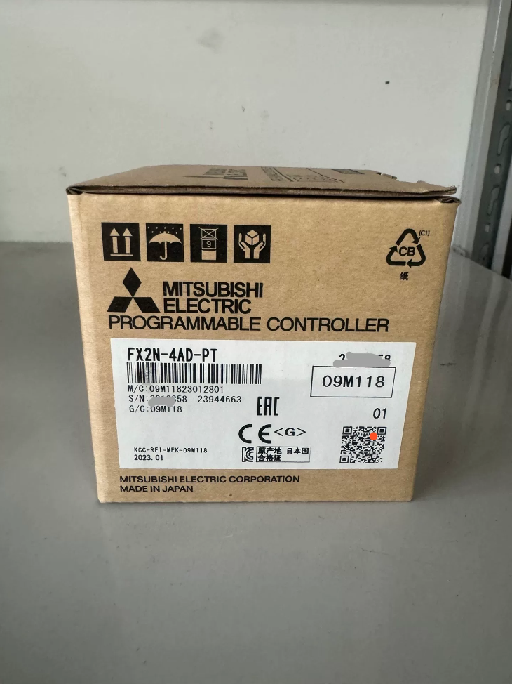
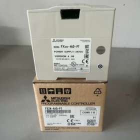
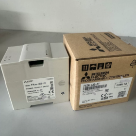
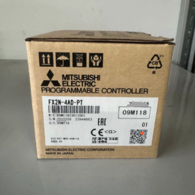
وحدة التوسعة الخاصة ل سلسلة FX PLC, مصمم للحصول على درجة حرارة مقاومة البلاتين PT100 ذات 4 قنوات و3 أسلاك. عفا عليه الزمن (توقف). يتم تنفيذ الاتصال عبر تعليمات تسجيل الذاكرة المؤقتة من/إلى. 2- أجهزة الاستشعار السلكية PT100 غير مدعومة.
- تحليل رمز النموذج
| شريحة | وصف |
| FX2N | سلسلة PLC, وحدة التوسعة FX2N |
| 4إعلان | 4- مدخل تناظري للقناة |
| -PT | وحدة RTD خاصة لمقاومة البلاتين PT100; ليست وحدة AD للجهد/التيار للأغراض العامة |
- الكهربائية الأساسية & المواصفات الفنية
| غرض | مواصفة |
| الاستشعار المدعومة | 3- سلك PT100 (100 أوه); توفر الوحدة إثارة تيار مستمر 1 مللي أمبير للمستشعر |
| نطاق درجة الحرارة | -100 درجة مئوية ~ +600 درجة مئوية; فهرنهايت: -148 درجة فهرنهايت ~ +1112 درجة فهرنهايت |
| تنسيق الإخراج الرقمي | وضع: القيمة = درجة الحرارة ×10 (على سبيل المثال. 25.0 ⁄ → 250); وضع ℉: القيمة = ℉ ×10 |
| دقة | 0.2~0.3 درجة مئوية / 0.36~0.54 درجة فهرنهايت |
| دقة | ±1% من النطاق الكامل |
| وقت التحويل | 15 مللي للجميع 4 القنوات |
| قرار الإعلان | 12-قليل (بما في ذلك بت التوقيع) |
| مصدر الطاقة من جانب PLC | 5 V DC مأخوذ من ناقل التوسعة PLC, استهلاك 30mA; تيار مستمر خارجي 24 فولت للدائرة التناظرية للوحدة |
| نقاط الإدخال/الإخراج المحتلة | 8 نقاط (الإدخال أو الإخراج, لا توجد محطات فعلية مشغولة) |
| عزل | عزل Optocoupler بين الدوائر التناظرية والرقمية; لا العزل بين القنوات |
| وزن | تقريبا. 0.3 كجم; تركيب السكك الحديدية DIN |
| رمز التعريف BFM#30 | K2040; القراءة بواسطة البرنامج للتحقق من وجود الوحدة |
| وحدات المعالجة المركزية PLC المتوافقة | FX0N/FX1N/FX2N/FX2NC/FX3G/FX3U/FX3UC; غير متوافق مع FX5U |
⚠️ القيد الصعب: 2-السلك PT100 غير مدعوم. سيؤدي التوصيل القسري لأجهزة الاستشعار ذات السلكين إلى انحراف شديد في درجة الحرارة وقياس غير دقيق. يُسمح فقط باستخدام RTD بثلاثة أسلاك.
- الذاكرة العازلة الرئيسية (تلقي اقتراحات المستفيدين وملاحظاتهم وشكاويهم) قائمة (من = اقرأ / إلى = الكتابة)
| تلقي اقتراحات المستفيدين وملاحظاتهم وشكاويهم | ص / ث | وصف الوظيفة |
| #0 | دبليو | معيار PT100: K0 = JIS C1604‑1997 (دين3850); K1 = JIS C1604‑1981 القديم |
| #1~#4 | دبليو | متوسط عدد العينات لـ CH1‑CH4, النطاق 1‑4096, الافتراضي = 8; قيمة أعلى = تصفية أقوى, استجابة أبطأ |
| #5~#8 | ر | متوسط درجة الحرارة بـ °C لـ CH1‑CH4 (×10); تستخدم عادة في الهندسة |
| #9~#12 | ر | درجة الحرارة الحالية اللحظية بـ °C لـ CH1‑CH4 (×10) |
| #13~#16 | ر | متوسط درجة الحرارة بـ ℉ لـ CH1-CH4 (×10) |
| #17~#20 | ر | درجة الحرارة الحالية اللحظية بـ ℉ لـ CH1-CH4 (×10) |
| #21 | دبليو | اكتب K1 لاستعادة معايرة المصنع; قم بالتسجيل الذي تم مسحه تلقائيًا بعد ذلك |
| #28 | ر | مزلاج خطأ القناة (كسر الأسلاك, مزلاج خارج النطاق) |
| #29 | ر | سجل حالة الخطأ (شديد الأهمية); أعلام الإنذار المستندة إلى البت |
| #30 | ر | رمز تعريف الوحدة K2040 للتحقق من صحة الوحدة من جانب البرنامج |
تعريف البت لـ BFM29 لاستكشاف الأخطاء وإصلاحها
| قليل | وصف الخطأ | علاج |
| ب0 | إعداد المعلمة غير صحيح في BFM#0 | اضبط BFM#0 على K0 أو K1 |
| ب1 | متوسط العدد #1‑#4 من نطاق 1‑4096 | تعديل قيمة متوسط العينة |
| b2 | خطأ في الأجهزة, شذوذ الوحدة النمطية | استبدال الوحدة النمطية |
| ب10 | القيمة الرقمية خارج النطاق (كسر سلك الاستشعار / تجاوز درجة الحرارة) | تحقق من الأسلاك PT100; تحقق من المستشعر المحترق |
- إرشادات الأسلاك
- 3- سلك PT100 إلزامي. يجب أن تكون للموصلات الثلاثة مقاومة ومقطع عرضي متساوي قدر الإمكان.
- استخدم كبلات زوجية ملتوية محمية لأسلاك إشارة RTD; قم بالتوجيه بشكل منفصل عن الكابلات عالية الطاقة لتقليل التداخل.
- وحدة العرض مع 24V DC; قم بتأريض محطة FG بشكل موثوق.
- لا تقم أبدًا بتطبيق إشارات الجهد على أطراف PT, وإلا يحدث تلف دائم في الوحدة.
- تعيين رقم الوحدة: الوحدة الخاصة الأولى المجاورة لوحدة المعالجة المركزية هي الوحدة رقم.0, عد إلى اليمين كرقم 1, رقم 2, رقم 3. المعامل الأول لـ FROM/TO هو رقم الوحدة النمطية.
مثال بسيط لمنطق السلم (رقم الوحدة.0, قراءة قيمة CH1 المتوسطة إلى D0)
من K0 K5 D0 K1
D0 = متوسط درجة الحرارة CH1 ×10; على سبيل المثال. D0=250 يساوي درجة الحرارة الفعلية 25.0 درجة مئوية.
- توقف - استبدال المنتج & خيارات الترقية
FX2N‑4AD‑PT عفا عليه الزمن. الحلول مجمعة حسب منصة PLC.
1) احتفظ بمنصة عائلة FX3U/FX3UC
- FX3U-4AD-PT: الاستبدال المباشر للأجهزة, 4-قناة PT100, متوافق مع الوظيفة, من - إلى الاتصالات دون تغيير; التكيف البسيط للبرنامج مطلوب.
ملحوظة: يتم أيضًا التخلص التدريجي من FX3U‑4AD‑PT.
2) الترقية إلى منصة FX5U
FX5‑4AD‑PT: وحدة درجة حرارة RTD مخصصة لوحدة المعالجة المركزية FX5U.
مخطط بديل: وحدة الإدخال التناظرية العامة بالإضافة إلى جهاز إرسال RTD خارجي.
بديل متوافق مع طرف ثالث
وحدة متوافقة المحلية: TX2N-4AD-PT. دبوس متوافق مع ناقل التوسعة FX2N; تسجيل رسم الخرائط متطابقة, يسمح بمبادلة الأجهزة مباشرة.
- مطبات الاختيار & الشروط غير المطبقة
- ❌ لا يمكن استخدام أجهزة الاستشعار PT100 ذات السلكين.
- ❌ليس مخصصًا لمدخلات المزدوجة الحرارية (استخدم FX2N‑4AD‑TC للمزدوجات الحرارية من النوع K/J; وحدات PT وTC غير قابلة للتبديل).
- ❌ لا يوجد عزل بين القنوات. يؤدي فرق جهد الوضع المشترك بين نقاط قياس متعددة إلى حدوث تداخل; العزلة الخارجية مطلوبة.
- ✅ التطبيقات النموذجية: أفران, أنظمة معالجة المياه, براميل ماكينة القولبة بالحقن, التخزين البارد وقياس درجة الحرارة الصناعية الأخرى في حدود -100 ~ 600 درجة مئوية.
- بيئات عالية التدخل: زيادة متوسط عدد العينات في BFM1‑4 (تم ضبطه على 16-32) للتصفية الرقمية.
- تشخيص الأخطاء الشائعة
- قراءة ثابتة عند -1000 (-100 درجة مئوية) أو 6000 (600 درجه مئوية): على الأرجح انكسر سلك PT100 أو أسلاك ثلاثية الأسلاك خاطئة. تحقق مما إذا كان BFM29 b10 مضبوطًا على وضع التشغيل.
- انحراف شديد في درجات الحرارة: تحقق من المقاومة المتساوية لثلاثة أسلاك استشعار; تحقق من تأريض الدرع; الابتعاد عن كابلات الطاقة.
- قراءة جميع القيم صفر عبر تعليمات FROM: رقم الوحدة خاطئ; قوة الناقل 5V غير كافية. اقرأ رمز التعريف BFM30 لتأكيد الاتصال.
- تقلبات القراءة الشديدة: زيادة متوسط عدد العينات في BFM1‑4.
تذكير بتمييز الوحدة: FX2N‑4AD‑PT لـ PT100 RTD مقابل FX2N‑4AD‑TC للمزدوجات الحرارية K/J. لا يمكن تبادل الأجهزة.
حالات تطبيق FX2N‑4AD‑PT في المجال الصناعي
خصائص الوحدة: 4اقتناء قناة PT100 RTD بثلاثة أسلاك, توقف. تبادل البيانات عبر تعليمات FROM‑TO BFM. مناسبة لمراقبة درجة الحرارة متعددة النقاط, التعامل مع الإنذارات والتحكم في درجة الحرارة ذات الحلقة المغلقة PID للمعدات الصغيرة والمتوسطة الحجم. أربع حالات صناعية عملية أدناه, بما في ذلك تكوين الأجهزة, تعيين نقطة القياس, منطق العملية, مقتطفات البرنامج الرئيسية, ملاحظات التشغيل وتحذيرات المخاطر في الموقع.
قضية 1: مراقبة درجة الحرارة متعددة النقاط للتخزين البارد الصغير / مبرد (صناعة التبريد)
أجهزة النظام
بلك: FX2N-32MR; وحدة خاصة: FX2N-4AD-PT (رقم الوحدة.0)
أجهزة الاستشعار: 4 قطع من الفئة A 3 أسلاك PT100
تعيين نقطة القياس
CH1: درجة الحرارة المحيطة للتخزين البارد
CH2: درجة حرارة الغاز الراجع للمبخر
CH3: مخرج المكثف-درجة حرارة الماء
CH4: درجة حرارة مخرج الماء المبرد
المحركات: 2 الضواغط, مروحة المكثف, إنذار مسموع ومرئي; عرض درجة الحرارة عبر شاشة اللمس HMI
متطلبات العملية
- عند درجة حرارة التخزين> 10 درجة مئوية: ضاغط 1 يبدأ; درجة الحرارة> 12 درجة مئوية: ضاغط 1 + 2 تشغيل في وقت واحد.
- عندما تنخفض درجة الحرارة إلى 6 درجات مئوية: إيقاف الضاغط 1; تنخفض درجة الحرارة إلى 3 درجات مئوية: أوقف كلا الضاغطين.
- تم إطلاق الإنذار لدرجة الحرارة أقل من 2 درجة مئوية (درجة حرارة منخفضة للغاية); يؤدي انقطاع سلك المستشعر إلى حدوث خلل في التعشيق لمنع بدء تشغيل الضاغط.
- تم تحميل جميع قيم درجة الحرارة إلى HMI; تم تمكين تسجيل الأحداث بشكل يتجاوز الحد.
تكوين المفتاح
- بفم0 = ك0 (معيار DIN PT100); BFM1‑4 = K16 (16- متوسط العينة لمنع التداخل الميداني داخل مخزن التبريد).
- قراءة متوسط درجة الحرارة 4 القنوات من BFM5~8 (القيمة الخام = درجة الحرارة ×10).
- اقرأ BFM29 للتعرف على انقطاع الأسلاك واكتشاف أخطاء الأجهزة; إيقاف تشغيل ضاغط التعشيق عند حدوث خطأ لتحقيق حماية المعدات.
مقتطف المفتاح (GX - سلم المطور)
M8002 // نبض التهيئة
من K0 K30 D10 K1 // قراءة رمز تعريف الوحدة
CMP K2040 D10 M0 // قارن للتحقق من صحة FX2N‑4AD‑PT
M8000
من K0 K5 D0 K4 // اقرأ متوسط درجة الحرارة CH1‑CH4 إلى D0‑D3
من K0 K29 K4M10 K1 // قم بتعيين بتات حالة الخطأ إلى M10‑M25
قسمة D0 على 10 للحصول على درجة حرارة التخزين الفعلية; استخدم تعليمات مقارنة منطقة ZCP لمنطق عتبة بدء وإيقاف الضاغط.
المخاطر في الموقع
بيئة التخزين البارد رطبة; حافظ على كتل طرفية PT100 مقاومة للرطوبة. 2- سلك PT100 ممنوع منعا باتا بسبب الانجراف الشديد. لا يوجد عزل قناة إلى قناة; تطبيق تأريض درع نقطة واحدة عندما تشترك مجسات متعددة في الأرض المرجعية.
قضية 2: التحكم في درجة حرارة خزان بسترة الطعام (صناعة تجهيز الأغذية)
تكوين الأجهزة
بي ال سي FX2N-64MR; FX2N-4AD-PT (رقم الوحدة.0); وحدة الإخراج التناظرية FX2N‑4DA
3 قطع من 3 أسلاك PT100:
CH1: درجة حرارة المواد داخل الخزان (ملاحظات التحكم الرئيسية PID)
CH2: درجة حرارة الماء الداخل للمبادل الحراري
CH3: درجة حرارة منفذ التفريغ
CH4: قناة احتياطية
المحركات: مرحل الحالة الصلبة SSR للتدفئة الكهربائية; مضخة الدورة الدموية; صمام تحويل التفريغ; PID ذو حلقة مغلقة عبر تعليمات FNC88.
متطلبات العملية
- قم بتسخين المادة حتى 92 درجة مئوية واحتفظ بها لمدة 15 ثانية. افتح صمام التفريغ عند الوصول إلى نقطة الضبط; تحويل المواد غير المؤهلة لإعادة التدوير.
- يحظر التفريغ عند درجة الحرارة أقل من 85 درجة مئوية. قطع مخرجات التدفئة على الفور, قم بتشغيل نظام الإنذار والإيقاف عند انقطاع الأسلاك PT100 لمنع خطر الحروق الجافة.
- يعرض HMI ثلاث قراءات لدرجة الحرارة; تسجيل بيانات العملية لتلبية متطلبات الامتثال لنظام تحليل المخاطر ونقاط التحكم الحرجة (HACCP)..
أبرز مميزات البرنامج
- د0 (قراءة CH1) بمثابة PID PV (متغير العملية, القيمة الخام ×10); نقطة الضبط SV = 920 تمثل 92.0 درجة مئوية.
- تم إرسال إخراج PID إلى FX2N‑4DA, توليد إشارة تناظرية 0-10 فولت لقيادة تنظيم طاقة SSR.
- عندما BFM29 b10 (علم قطع الأسلاك) قيد التشغيل: إعادة ضبط مخرج PID وإخراج التسخين بالقوة Y0.
ملاحظات التكليف
تتميز حلقة التسخين بالجمود الحراري الكبير & تأخر; قم بضبط معلمات P/I/D PID بشكل متكرر. قم بزيادة عدد متوسط BFM1 للتخفيف من الضوضاء الميدانية الناجمة عن المحرك.
قضية 3: قياس درجة الحرارة متعدد النقاط لفرن التجفيف في العبوة & آلات الطباعة
الأجهزة
FX2N-48MR + FX2N-4AD-PT
CH1: درجة حرارة مدخل الفرن
CH2: فرن القسم الأوسط (نقطة التحكم الرئيسية في العملية)
CH3: درجة حرارة مخرج الفرن
CH4: درجة حرارة الهواء العادم
المحركات: عناصر التسخين التي تعتمد على الملامس; تعشيق المروحة; قطع التدفئة عند ارتفاع درجة الحرارة.
منطق العملية
- تحكم ثابت في درجة الحرارة مع نقطة ضبط قابلة للتعديل 80-130 درجة مئوية, أخذ درجة حرارة الفرن المتوسطة CH2 كملاحظات رئيسية.
- قم بتشغيل تعشيق درجة الحرارة الزائدة وقطع كل طاقة التسخين إذا كانت درجة حرارة المخرج> 150 درجة مئوية; يحظر تنشيط التدفئة إذا كانت المروحة معيبة.
- قم بتحميل أربع نقاط درجة حرارة إلى HMI وقم بتسجيل أحداث درجة الحرارة الزائدة.
ملاحظات هندسية
ارتفاع درجة الحرارة المحيطة بالفرن; نشر كابلات محمية ذات درجات حرارة عالية لأجهزة استشعار PT100. افصل كابلات الإشارة عن كابلات الطاقة بمسافة لا تقل عن 20 سم. قم بتثبيت الفلتر على وحدة إمداد الطاقة بجهد 24 فولت.
>⚠️ لا ينطبق على درجة الحرارة فوق 600 درجة مئوية (الحد الأعلى لنطاق قياس الوحدة). استخدم وحدة المزدوجة الحرارية FX2N‑4AD‑TC بدلاً من ذلك لتطبيقات درجات الحرارة المرتفعة.
قضية 4: مراقبة درجة الحرارة للمفاعل الكيميائي المتحرك الصغير (الصناعة الكيميائية الدقيقة)
تكوين الأجهزة
FX2N-48MR, FX2N-4AD-PT; 4-قناة 3 أسلاك PT100
CH1: درجة حرارة المادة داخل المفاعل (السيطرة الرئيسية)
CH2: تسخين السترة - درجة حرارة متوسطة
CH3: درجة حرارة مخرج مياه التبريد
CH4: درجة حرارة الجدار الخارجي للمفاعل
النواتج: صمام الملف اللولبي للتدفئة, صمام الملف اللولبي لمياه التبريد, محرك المحرض, إخراج التنبيه.
منطق العملية
- افتح صمام التسخين أثناء مرحلة التسخين; تسخين قريب عند الوصول إلى درجة الحرارة المستهدفة; فتح صمام مياه التبريد تلقائيًا للحماية من درجة الحرارة الزائدة.
- يدخل النظام إلى الحالة الآمنة عند انقطاع سلك المستشعر: إغلاق صمام التدفئة, مياه التبريد المفتوحة, تفعيل إنذار مسموع ومرئي.
- مقارنة درجات الحرارة متعددة القنوات للإنذار عند حدوث فرق كبير في درجة الحرارة بين الجزء الداخلي للمفاعل والغلاف, لتجنب ارتفاع درجة الحرارة المحلية.
اعتبارات المخاطر
الجو المسببة للتآكل داخل مصنع الكيماويات; اعتماد الأكمام الحماية المضادة للتآكل لتحقيقات PT100. لا يوجد عزل بين القنوات; تقلب القراءة المحتمل الناجم عن إزاحة الجهد الأرضي بين نقاط القياس; تنفيذ التأريض أحادي الطرف في جانب المستشعر.
قواعد التنفيذ الهندسية العامة (شائعة في أربع حالات)
- التحقق من رقم الوحدة: أول وحدة خاصة مجاورة لوحدة المعالجة المركزية = K0, قم بالزيادة إلى K1/K2 لليمين. يجب أن يتطابق المعامل الأول من FROM/TO مع رقم الوحدة الفعلية. اقرأ BFM30 = K2040 للتحقق من صحة تكوين الأجهزة.
- الانضباط الأسلاك: استخدم فقط أجهزة استشعار PT100 ذات 3 أسلاك. تطابق مقاومة ثلاثة أسلاك; التأريض بنقطة واحدة للدرع; يحظر بشدة حقن الجهد في محطات الاستشعار.
- نموذج معالجة الأخطاء: اقرأ BFM29 في كل دورة مسح. يشير b10 ON إلى انقطاع سلك القناة. يجب أن ينفذ البرنامج قفل الأمان بدلاً من الإنذار فقط; خفض انتاج التدفئة لمنع وقوع الحوادث.
- تحويل القراءة: قيمة التسجيل الخام = درجة الحرارة الفعلية ×10; على سبيل المثال. `D0=250 →25.0°C`.
- تم إيقاف إرشادات الترقية: بالنسبة لنظام FX2N الحالي الذي ينتقل إلى FX3U: حدد FX3U‑4AD‑PT. بالنسبة للهجرة إلى FX5U: اعتماد FX5-4AD-PT.



NH42-63-318x560.png "مفاتيح النقل التلقائي من نوع الكمبيوتر الشخصي CHINT (المنشطات الأمفيتامينية)NH42-63/4SZ")



