 المقاولين,قاطع الدائرة,الاستشعار,التشفير,بلك,محول

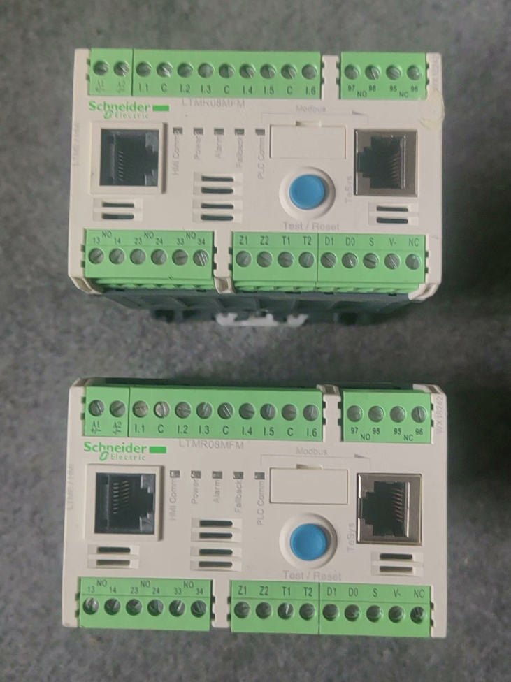

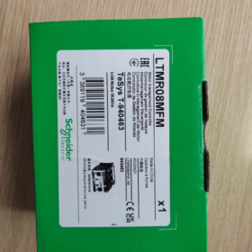
شنايدر TeSys‑T (LTMR Series) Motor Management Controller — Application Scenarios
TeSys‑T is an intelligent motor‑protection & monitoring unit. Core values: comprehensive motor protection + I/O logic control + Modbus RTU bus for motor‑data & fault‑log upload. It targets three‑phase asynchronous motors requiring fine‑grained protection, remote monitoring and predictive maintenance. An external contactor is required for motor start‑stop.
حالة المنتج: Planned Obsolete, End‑of‑Life Date: Sep 30, 2026
مسلسل: TeSys‑T Intelligent Motor Management Unit, Modbus‑RS485 communication, 0.4‑8A motor circuit protection & يراقب
- انهيار رمز النموذج
| مجال | شفرة | وصف |
| LTM | LTM | TeSys‑T motor management system series |
| ر | ر | Controller body |
| 8 | 8 | Rated current measuring range 0.4‑8 A |
| م | م | تواصل: مودبوس ار تي يو (RS485) |
| ف | ف | Control supply: 100‑240 V AC |
| م | م | Terminal version M (standard terminals, 6من / 3DO relay outputs) |
- الكهربائية الرئيسية & مواصفات الأجهزة
| غرض | قيمة |
| Motor current measurement range | 0.4 … 8 A |
| التحكم في جهد الإمداد | 100‑240 V AC; operating tolerance: 93.5~264 V AC, 50/60 هرتز |
| Logic Inputs (من) | 6‑channel AC‑type logic inputs; 0‑40 V = OFF state, 79‑264 V = ON state |
| مخرجات التتابع (يفعل) | 3لا + 1NO+1NC fault relay; contact rating: AC250V/5A; DC30V/5A |
| واجهة الاتصالات | Modbus‑RTU RS485; المزدوج RJ45 + terminal block port; معدل الباود:1.2~19.2 kbit/s; address range:1‑247 |
| Overall dimension (الارتفاع × العرض × العمق) | 61 × 91 ×122.5 mm; وزن:0.53 كجم; تركيب السكك الحديدية DIN |
| Operating ambient temperature | -20 ℃ … +60 ℃; درجة حرارة التخزين:‑40 ℃~+85 ℃; condensation prohibited |
| تصنيف الجهد العزل واجهة المستخدم | 690 V; pollution degree 3, overvoltage category III |
| عزم الدوران الأسلاك | 0.5‑0.6 N·m; wire gauge:0.2‑2.5 mm² solid / flexible cable |
ثالثا. Built‑in Protection Functions
Thermal overload long‑time protection, locked‑rotor protection, خسارة المرحلة, عدم توازن المرحلة, phase‑reversal, earth‑leakage protection
Recordable data: أحداث خطأ, البدء الحالي, operating hour counter, trip context, residual thermal capacity; pre‑alarm supported
توسع: with LTME expansion module for voltage measurement, power‑factor and load‑variation protection
- In‑depth Operating Principle
- Current acquisition: Built‑in 3‑phase current transformers measure motor true RMS current; integrated earth‑fault current detection.
- Thermal model: Embedded motor thermal‑memory algorithm simulates motor temperature rise for overload protection; cooling delay applied after tripping.
- I/O logic: 6 DIs receive external start/stop / local‑remote commands; 3 relay outputs drive contactor coils; fault relay provides alarm signal.
- Modbus bus: Upload current, thermal status, رموز الخطأ, operating status; receive remote start‑stop and parameter modification commands.
- Local blue TEST/RESET push‑button: manual fault reset & local test; front‑panel LED indicators (POWER / يجري / إنذار / FAULT).
ملحوظة: This unit performs only protection & التحكم المنطقي. Main‑circuit contactor must be externally wired to build a complete motor starter circuit.
- Key Terminal Definitions (ملخص)
A1/A2: Controller power supply, 100‑240 VAC
C1‑C6: 6 logic input channels (من)
21‑24, 31‑34: 3 NO relay outputs (for contactor driving)
95‑96‑97: Fault relay, 1لا + 1NC
مودبوس: Dual‑port RS485 (RJ45 + كتلة المحطة الطرفية), supports daisy‑chain networking
- يرقي & Replacement Solution (Official TeSys‑Tera New‑generation Series)
TeSys‑Tera adopts separated architecture: controller body + external CT sensors. Direct‑pin‑to‑pin hardware replacement against legacy LTMR is not feasible; current‑sensing wiring modification is required.
| مخطط | الوحدة الرئيسية | Current Sensor | Applicable Current Range |
| Scheme 1 | LTMTMFM (مودبوس, 100‑240 VAC/DC) | LTMTCTV3UT | 0.3‑3 A |
| Scheme 2 | LTMTMFM (مودبوس, 100‑240 VAC/DC) | LTMTCTV25UT | 2.5‑25 A |
⚠ Upgrade Risks:
- Old LTMR integrates internal CT; new Tera uses external CT, cabinet wiring modification required.
- Modbus register mapping & parameters are not fully compatible; PLC program modification & commissioning are mandatory.
- I/O terminal layout is completely different; secondary‑wiring inside control cabinet must be reworked.
سابعا. سيناريوهات التطبيق النموذجية
Three‑phase asynchronous motors such as pumps, المشجعين, compressors and conveyors; معالجة المياه, علم المعادن, oil‑gas, كيميائية, cement industries; critical motor loops requiring PLC‑based bus access for motor‑protection status and fault‑log reading.
ثامنا. ملاحظات الاختيار & Boundary Conditions
- Max measuring current 8 A; not applicable for motors with rated current higher than 8 A.
- DIs are AC‑voltage inputs, not dry‑contact inputs; external supply voltage is required for contact closure.
- Max relay output switching frequency: 2 هرتز; unsuitable for high‑frequency cycling applications.
- Cabinet‑level protection is required for condensation‑prone or corrosive environments.
- Planned end‑of‑life: Sep‑30‑2026; new‑project designs shall adopt TeSys‑Tera preferentially.
- General‑process Industrial Equipment (الأكثر شيوعًا)
- معجب & Pump Circuits
مضخات تعميم, cooling pumps, sewage pumps, makeup‑water pumps, smoke‑exhaust fans, supply‑return fans, cooling‑tower fans.
Values: الزائد, الدوار المقفل, خسارة المرحلة & earth‑fault protection; upload running current, fault status and runtime; underload protection for pump dry‑run prevention.
الصناعات: التدفئة والتهوية وتكييف الهواء, معالجة مياه الصرف الصحي, water‑works, building MEP.
- الناقلون, belt feeders & screw feeders
سيور ناقلة, scraper conveyors, screw feeders, bucket elevators.
Values: fast trip upon mechanical jamming; phase‑unbalance & earth‑fault protection; fault history for jam‑incident analysis; interlock‑logic support.
الصناعات: التعدين, مواد البناء, grain storage, logistics handling, المعالجة الكيميائية.
- الضواغط & وحدات التبريد
Screw air compressors, ضواغط التبريد, process compressors.
Values: prevent locked‑rotor / overload caused by liquid‑slugging; thermal‑model winding protection; upload motor status to PLC / SCADA via fieldbus.
- Water‑treatment & Municipal Industry (High‑volume TeSys‑T deployment)
Lift pumps, return‑flow pumps, agitator motors for chemical dosing, aeration blowers, bar screens, scrapers.
Site features: large quantity of geographically distributed motors; remote monitoring of current & faults to reduce on‑site inspection; high incidence of phase‑loss & earth‑fault faults.
Typical architecture: Modbus‑RTU multi‑drop networking with PLC, aggregating motor‑protection data to SCADA host.
- كيميائي & صناعة الأدوية
Reactor agitators, circulation pumps, metering pumps, material transfer pumps, أجهزة الطرد المركزي.
Values:
- Earth‑leakage protection mitigating motor damage from process‑media leakage.
- Complete fault event log for process traceability and GMP compliance.
- Phase‑reversal protection to prevent reverse rotation after maintenance phase swapping.
ملحوظة: Controller body cannot be installed directly in hazardous explosive areas; explosion‑proof enclosures / contactors are required.
- علم المعادن, أسمنت & Building‑materials
Dust‑removal fans, cooling fans, distributing actuators, unloading drives, small roller‑table motors.
Operating conditions: heavy shock‑loading, high dust; frequent locked‑rotor & phase‑loss events; combined thermal‑overload & fast locked‑rotor trip safeguards motor windings.
- Power‑plant Auxiliary Drives
Small auxiliary motors: cooling fans, lube‑oil pumps, seal‑water pumps.
Values: critical auxiliary equipment; pre‑alarm & fault‑snapshot recording for root‑cause analysis after incidents.
- Logistics‑packaging & ماكينات البلاستيك
سيور ناقلة, المحرضين, feeders, auxiliary drives for small extruders.
المزايا: local / remote mode selection via DI; contactor‑coil driving via DO eliminates numerous intermediate relays.
✅ Selection Criteria for TeSys‑T
Choose LTMR if any condition below applies:
- Fieldbus communication required: read current, thermal‑capacity percentage, ساعات العمل, fault codes and fault snapshots.
- Valuable motors requiring full‑scope protection: thermal overload, الدوار المقفل, خسارة المرحلة, phase‑unbalance, phase‑reversal, earth‑fault, التحميل الزائد.
- Local‑remote dual control mode plus complex interlock logic; reduce intermediate‑relay count.
- On‑site requirement for fault logging for post‑event troubleshooting.
- Multi‑motor centralized monitoring network connected to PLC / سكادا.
❌ Unsuitable Application Scenarios
- Only simple thermal‑relay protection needed without communication or fault logging: select low‑cost LRD thermal overload relays instead.
- Motor full‑load current far exceeds built‑in CT range (max integrated‑CT LTMR:100 أ). Use new‑generation TeSys‑Tera with external CT for higher‑current motors.
- High‑frequency motor cycling: relay DO max switching frequency 2 Hz; contact wear will accelerate.
- Intrinsically‑safe hazardous zones: controller body cannot mount inside hazardous area.
- Single‑phase‑motor protection: TeSys‑T targets three‑phase induction motors.
📌 Old‑vs‑New Generation Summary
Legacy: LTMR series (على سبيل المثال. LTMR08MFM), planned EOL Sep‑30‑2026, built‑in current transformers.
جديد: TeSys‑Tera (LTMT series), external‑CT architecture, broader current coverage; preferred for new‑project engineering.
Thermal‑Overload Protection Principle of Schneider TeSys‑T (LTMR)
TeSys‑T does not rely on physical bimetallic‑strip deformation like conventional thermal relays. It implements thermal‑overload protection via electronic thermal‑model (virtual‑motor thermal‑memory algorithm) + true‑RMS three‑phase‑current sampling.
- Hardware Acquisition Stage
- Built‑in three‑phase current transformers sample true RMS stator current (not simple peak values).
- Integrated earth‑fault‑current detection circuit.
- Analog‑current signals are digitized by MCU for periodic load‑current refresh.
For LTMR08MFM: internal CT measuring range:0.4‑8 A for direct stator‑loop current measurement.
- جوهر: Virtual‑motor Thermal‑Model (Thermal Memory)
The controller runs a mathematical model simulating motor‑winding heat accumulation and heat dissipation:
theta_{virtual} \propto \int(I^2 \cdot t)dt
Heat accumulation: thermal‑capacity percentage rises when operating current exceeds motor rated current.
Heat dissipation: thermal‑capacity percentage decreases during stop or light‑load operation, simulating natural motor cooling.
Two key configurable parameters drive model behaviour:
- Motor rated current Ir: set according to motor nameplate full‑load current.
- فئة الرحلة (5/10/15/20/30), defines inverse‑time tripping characteristics.
📌 Thermal‑capacity percentage: internal variable 0‑100 %; overload trip triggers at 100 %. This value can be read via Modbus register.
Trip‑Class Definition
| فئة الرحلة | Trip Time @7.2 × Ir | Typical Motor Application |
| Class 5 | 4‑5 s | Fast‑starting motors |
| Class 10 | 6‑10 s | Standard general‑purpose three‑phase induction motors (most‑used) |
| Class 15 | 9‑15 s | Heavy‑duty start‑load applications |
| Class 20 | 12‑20 s | High‑inertia heavy‑start motors |
| Class 30 | 18‑30 s | Long‑start‑time high‑inertia loads (على سبيل المثال. مراوح كبيرة) |
- Overload Handling for Two Typical Operating Conditions
① Continuous running overload (persistent over‑current)
Motor runs continuously with I>Ir; virtual thermal‑capacity accumulates until reaching 100 %. The controller outputs trip command, de‑energizes contactor‑coil relay outputs and stops the motor. Over‑load fault code plus fault snapshot (3- المرحلة الحالية & thermal‑capacity at trip instant) are stored.
② Overload during motor start‑up (high‑magnitude starting inrush current)
Configured Trip‑Class permits short‑term high starting‑current without nuisance tripping; thermal‑model decays accumulated heat after start‑up completes.
⚠ Critical Feature: Thermal‑memory retention
After overload trip, virtual thermal‑capacity value does not reset immediately even if controller power supply remains alive. Model‑simulated cooling‑time must elapse or manual RESET is required.
Practical case: after motor trips from overload, windings remain hot. Instant reset & restart risks motor burnout. Thermal‑memory prevents premature restart and mimics real‑motor cooling behaviour.
- Pre‑alarm Function (Overload Early Warning)
Configurable thermal‑capacity threshold (e.g. 80 %). When virtual thermal‑capacity exceeds threshold, overload pre‑alarm activates without tripping. Warning signal can be transmitted via relay DO or Modbus for predictive maintenance before unplanned shutdown.
- مقارنة: Conventional Bimetallic Thermal Relay vs TeSys‑T LTMR Electronic Thermal‑model
| غرض | Traditional LRD Bimetallic Thermal Relay | TeSys‑T LTMR Electronic Thermal‑model Overload Protection |
| Protection Principle | Bimetallic‑strip physical thermal deformation | Software‑based virtual thermal‑model with RMS‑current sampling |
| Thermal‑memory characteristic | Heat vanishes upon power‑loss; no thermal retention | Thermal‑memory can be retained upon power‑loss (شكلي) |
| Ambient‑temperature influence | Strong cabinet‑temperature‑dependent, notable deviation | Software temperature compensation; low environmental‑temperature sensitivity |
| Trip‑class setting | مُثَبَّت (limited models support adjustment) | Software‑configurable Class 5‑30 |
| Data‑availability | No status output | Bus‑readable thermal‑capacity, fault snapshots, current measurements |
- Boundary‑conditions & القيود
- Overload protection protects motor‑winding thermal accumulation, not power cables; separate circuit‑breaker required for cable‑conductor protection.
- Phase‑loss / phase‑unbalance accelerates thermal‑model accumulation and advances trip threshold.
- Locked‑rotor and earth‑fault are independent protection functions, not part of overload logic.
- Adjust Trip‑Class if actual motor‑cooling condition deviates from internal model (على سبيل المثال. forced‑air‑cooled motor).
- LTMR thermal‑model is designed for standard three‑phase induction motors. Direct reuse for VFD‑fed or special‑purpose motors is invalid; parameter tuning is mandatory.
- Fault‑reset Logic
- Auto‑reset: parameter‑enabled; reset occurs only after thermal‑model cools down to safe thermal‑capacity level.
- إعادة الضبط اليدوي: local front‑panel RESET button, DI terminal reset signal, or Modbus‑bus reset command.
Forbidden operation: repeated forced restarts before motor cools after thermal trip.
- رمز الخطأ
Thermal‑overload trip fault code: OL1. Fault log stores timestamp, three‑phase current and thermal‑capacity percentage, retrievable via Modbus.



NH42-63-318x560.png "مفاتيح النقل التلقائي من نوع الكمبيوتر الشخصي CHINT (المنشطات الأمفيتامينية)NH42-63/4SZ")



