 Schütz,Leistungsschalter,Sensor,Encoder,SPS,Konverter

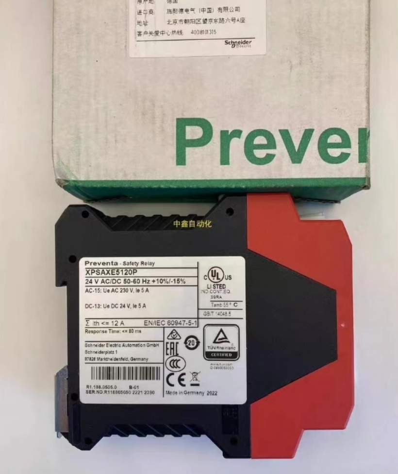

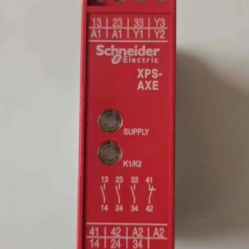
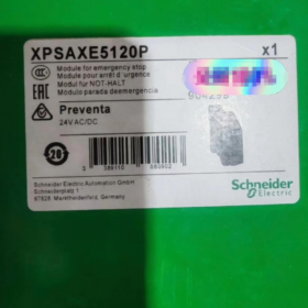
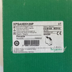
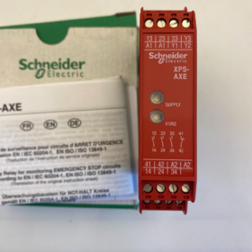
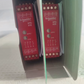
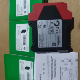
Produktpositionierung: Safety module for emergency stop & Überwachung von Schutztürschaltern (Kategorie 0 stoppen). Replacement for legacy XPSAX
Typische Modelle: XPSAXE5120P / XPSAXE5120C
XPSAXE5120P: Abnehmbare Schraubklemmen
XPSAXE5120C: Removable spring terminals
Stromversorgung: 24 V AC/DC (Wechselstrom & Gleichstrom universal)
Montage: 35 mm DIN-Schiene, Breite 22.5 mm
Gesamtabmessungen (B×H×T): 22.5 × 99 × 114 mm
✅ Safety Ratings
PL e / Kat.4 (IN ISO 13849-1)|SIL CL3 (IEC 61508 / IEC 62061)
Anwendbare Standards: IN ISO 13850 (Not-Aus), IN ISO 14119 (Safety Interlock Switches)
- Kanal & Terminaldefinition (XPSAXE5120)
1) Stromversorgung
A1, A2: Stromversorgung des Moduls, 24 V AC/DC
2) Sicherheitseingänge (Dual-channel monitoring, dual NC emergency stop / safety switches recommended)
S11-S12: Kanal 1
S21-S22: Kanal 2
Detects short circuits and wire breaks between dual channels; synchronous response window between channels <0.5 s
3) Start Circuit (Zurücksetzen)
S33, S34
Short S33 and S34 → Automatic Reset
Connect external NO pushbutton between S33 and S34 → Manual Reset
4) External Contactor Feedback Circuit (Obligatorisch!)
Y1, Y2
Wire auxiliary NC contacts of main circuit contactor in series to Y1-Y2;
Funktion: Prevent unexpected machine startup if contactors weld closed (anti-bounce restart protection).
5) Sicherheitsausgänge (3 sets of instantaneous NO safety contacts)
13-14, 23-24, 33-34
Three independent Sicherheitsrelais contacts for de-energizing power contactor coils.
Single contact rated current: 6 A; AC-15: 360 VA continuous load; DC-13: 24 V/1.5 A.
6) Auxiliary PLC Signal Output (Non-safety circuit!)
41-42: 1 set of NC signal contacts
Only used for status feedback to PLC. Strictly prohibited for safety cut-off circuits.
7) LED-Anzeigen
PWR: Power supply present
LAUFEN: Safety circuit closed, outputs energized
- Betriebslogik
- Power on; emergency stop reset & safety gate closed → S11-S12 / S21-S22 conductive
- Y1-Y2 feedback circuit closed (main contactor de-energized)
- Drücken Sie die Reset-Taste (or auto-reset active) → internal dual relays energize
- 13-14 / 23-24 / 33-34 schließen, machine operation permitted
- Emergency stop triggered / gate opened / wiring fault detected → three safety outputs open instantaneously (≤80 ms)
- Reset is blocked until all faults are cleared
- Recommended Typical Wiring Schemes
- Standard Scheme (Dual NC Emergency Stop + Manueller Reset + Rückmeldung)
A1/A2: 24 V-Stromversorgung
Dual NC emergency stop: Common power feed, two channels routed separately to S11-S12 and S21-S22
NO start pushbutton wired across S33-S34
Auxiliary NC contacts of main power contactor wired in series to Y1-Y2
13/23/33 connected to power; 14/24/34 wired in parallel to drive main contactor coil
- Verbotene Praktiken
Do NOT use 41-42 signal contacts for safety cut-off
Do NOT omit Y1-Y2 feedback circuit (losses anti-weld protection, cannot achieve Cat.4)
Single-channel wiring only achieves PL d/Cat.3, fails high-end machine requirements
- Key Notes for Legacy XPSAX Replacement (Common Application)
Legacy model: XPSAX5120 → Replace with XPSAXE5120P
- Terminal assignments not fully pin-to-pin compatible, direct plug replacement is impossible; terminal wiring must be rechecked
- XPSAXE adopts removable terminals for easier cabinet wiring and maintenance
- Height dimension increased; verify available installation space
- Identical operating logic and safety rating
- Series Selection Comparison Reference
XPS-AXE: Nothalt / Schutztürüberwachung, 3 KEINE Sicherheitsausgänge, with feedback; Kategorie 0 stoppen
XPS-AC: Kompakt 22.5 mm Breite, similar functions with minor load capacity differences
XPS-AK: Supports safety light curtains, Sicherheitsmatten; erweiterte Funktionen, höhere Kosten
- Allgemeine Fehlerbehebung
- RUN LED off after power-up
Verify S11/S21 both channels are conductive
Check continuity of Y1-Y2 (confirm contactor not welded)
- Machine cannot restart after emergency stop release
Confirm reset mode: short S33 and S34 for automatic reset
Short circuit or wire break detected in dual input channels
- Random tripping during operation
Total wiring resistance of input cables exceeds limit (≤50 Ω); use larger cross-section cables for long wiring runs
Ich kann dafür sorgen:
✅ Text version of standard wiring schematic
✅ Full datasheet parameters of XPSAXE5120P
✅ Terminal comparison table: XPSAX vs XPSAXE
Application Scenarios of Schneider XPS-AXE (XPSAXE5120P/C) Sicherheitsrelais
Core Position Recap
Only supports two safety input types: dual-channel dual NC emergency stop pushbuttons + safety gate interlock switches
Sicherheitsbewertung: PL e / Kat.4, SIL CL3, Kategorie 0 instantaneous power cut-off
Not compatible with: Sicherheitslichtvorhänge, Sicherheitsmatten, two-hand control devices;
Standardkonfiguration: External contactor feedback circuit (Y1-Y2), 3 safety NO outputs, 1 PLC status signal output; supports Manual Reset / Automatischer Reset.
- Supported Safety Functions
- Emergency Stop Circuit Monitoring (ISO 13850) : Monitoring machine main emergency stop and zone emergency stop via dual channels
- Safety Guard Door Interlock Monitoring (ISO 14119) : Mechanical fences, access doors, protective hood interlock switches
Applicable switches: Dual NC safety gate switches, magnetic safety interlock switches (Öffnerkontakte)
- Industry Typical Applications
1) Allgemeine Werkzeugmaschinen & Metalworking Equipment
CNC-Drehmaschinen, Bearbeitungszentren, Fräsmaschinen, Schleifmaschinen
Small presses, hydraulic machines, Abkantpressen, Schere
Cutting machines, Schleifmaschinen, deburring equipment
Verwendung: Machine panel emergency stop + electrical cabinet door / protective hood interlock
2) Verpackung, Drucken & Rubber/Plastics Machinery
Vertical form fill seal machines, flow wrappers, Kofferpacker, auxiliary palletizing equipment
Blow molding machines, injection molding auxiliary equipment, small extrusion lines
Druckmaschinen, Laminatoren, die-cutters
Merkmale: Risk of nipping between rollers and conveyors; immediate machine shutdown required upon guard door opening
3) Fördern & Logistics Automation Equipment
Bandförderer, Rollenbahnen, transfer units, Hub-Transfertische
Small automated storage systems, sorting workstations, single units on packaging lines
Guard fence interlock at roller conveyor corners
4) Small Robot Workcells
Compact 6-axis robots, SCARA robot single-unit safety fencing
⚠️ Limitation: Only for fence door + workstation emergency stop monitoring. Additional XPS-AK safety relay required if safety light curtains are deployed.
5) Essen & Pharmazeutische Verpackungsausrüstung
Abfüllmaschinen, capping machines, Etikettiermaschinen, auxiliary sterilization equipment
Food cutting and material handling standalone machines
Vorteile: 24 V AC/DC wide range power supply, kompakte DIN-Schienenmontage; meets CE requirements for export machinery
6) Holzbearbeitung & Composite Processing Machinery
Edge banders, nesting CNC routers, Graviermaschinen, Schleifmaschinen
Plattenzuschnitt, small composite hot-press equipment
7) Test Benches & Custom Automation Machinery
Component air-tightness test stations, press-fit custom machines, torque tightening equipment
Small lithium battery assembly equipment, inspection tooling
Widely adopted for safety circuit construction on custom machines to satisfy EU Machinery Directive & CE marking
- Typical Wiring Application Schemes
- Scheme A: Single Machine with Emergency Stop + Sicherheitstor (Am häufigsten)
Two channels wired in series: Dual NC emergency stop + dual NC safety gate. Machine shuts down immediately upon activation of either device.
Suitable for standalone equipment fitted with protective hoods and safety fences.
- Scheme B: Dual-channel Emergency Stop Monitoring Only
Both channels connected to dual NC emergency stop without safety gates; used for open-frame equipment only equipped with emergency stop protection.
- Scheme C: Safety Guard Door Monitoring Only
Two channels connected to safety gate switches, working with zone emergency stops to form the complete machine safety system.
- Ungeeignete Anwendungen (Auswahlfallen)
- Required interface with safety light curtains, Sicherheitsmatten, safety edges → Select XPS-AK / XPSUAK
- Required time-delayed shutdown (Category1/2 stop) → XPS-ATE time-delay series
- Required two-hand control function → XPS-AB
- Mixed multiple safety signals (Lichtvorhang + Sicherheitstor + Not-Aus) → Universal XPSUAF safety module
- Solid-state safety outputs required (keine mechanischen Kontakte) → Models with semiconductor outputs
- Key Selection Reminders
Direct replacement for legacy XPSAX5120: XPSAXE5120P (Schraubklemmen) / XPSAXE5120C (Federklemmen)
Compact cabinet alternative with equivalent functions: Compare XPSAC5121
To achieve Cat.4 safety rating, Y1-Y2 contactor feedback circuit cannot be omitted
I can organize:
✅ Text version of standard XPSAXE wiring diagram
✅ Safety function description text for CE risk assessment (directly usable in machine manuals)
Detailed Analysis of Y1-Y2 External Contactor Feedback Circuit for Schneider XPS-AXE (XPSAXE)
Terminals Y1, Y2
Connect auxiliary Normally Closed (NC) contacts of main power contactors
⚠️ This circuit must not be omitted to achieve PL e / Kat.4
- Four Core Functions
1) Anti-Weld Contactor Protection (Most Critical)
Szenario: Main contactor main contacts weld closed due to high current ablation or mechanical jamming.
Normal shutdown: Contactor coil de-energized, main contacts open; auxiliary NC contacts restore closed state, Y1-Y2 conductive.
Weld fault condition: Safety relay cuts outputs, but main power circuit remains energized; auxiliary NC contacts stay open → Y1-Y2 circuit opens.
XPS-AXE detects open Y1-Y2 circuit, locks safety system and blocks reset, preventing unexpected machine startup and severe safety hazards.
- Closed-loop safety monitoring to meet EN ISO 13849 Kat.4
Cat.4 safety standard requires the system to detect faults of its actuators (Schütze).
If Y1-Y2 feedback is omitted:
Safety rating downgrades to PL d / Kat.3, failing requirements for high-end machinery and CE export certification.
- Prevent Recurring Start-Stop Oscillation
After machine trips without feedback monitoring:
The safety relay may repeatedly attempt to energize/de-energize contactors in certain conditions, accelerating contact arc erosion.
Feedback logic ensures: Reset is only permitted after the contactor is fully de-energized.
- Logic Interlock to Verify Actuator Status
Reset conditions of safety relay add one prerequisite: Confirm all power contactors are in de-energized state.
Full reset sequence conditions:
- Nothalt / safety gate dual-channel inputs return to closed state
- Y1-Y2 feedback circuit conductive (contactor confirmed open)
- Execute manual or automatic reset
- Standard Wiring Rules
- Wire auxiliary NC contact of contactor in series. DO NOT use NO contacts!
- Only contacts can be wired between Y1 and Y2; parallel components are prohibited.
- Multiple contactor setup: Auxiliary NC contacts of all main contactors must be wired in series into Y1-Y2 (reset allowed only when all contactors open).
- Common Wiring Mistakes & Consequences
❌ Mistake 1: Direct short-circuit Y1-Y2
Folge: Feedback function disabled, loss of weld detection. Safety rating downgraded to PL d, Cat.4 claim invalid; non-compliant during CE audit. Risk of sudden machine startup if contactor welds.
❌ Mistake 2: Connect contactor NO contacts
Folge: Y1-Y2 opens when contactor energizes → safety relay trips continuously during machine operation, equipment cannot run.
❌ Mistake 3: Only one contactor connected in feedback while multiple power contactors exist
Folge: Weld failure of any unmonitored contactor cannot be detected, creating safety blind spot.
- Zusammenfassung in einfacher Sprache
The safety relay issues the shutdown command. Y1-Y2 feedback confirms whether the contactor actually opens as commanded.
If contactor sticks closed and fails to open, the safety relay locks the system and prevents machine restart.
Supplementary Notes for XPS-AXE
Feedback circuit belongs to safety-related wiring; separate routing from power cables is recommended.
For local machines without export requirements where only PL d is demanded, shorting Y1-Y2 is theoretically possible but not recommended by Schneider official manuals. All risks shall be borne by the machine manufacturer.





NH42-63-318x560.png "Automatische Transferschalter vom Typ CHINT PC (ATS)NH42-63/4SZ")



