 Schütz,Leistungsschalter,Sensor,Encoder,SPS,Konverter

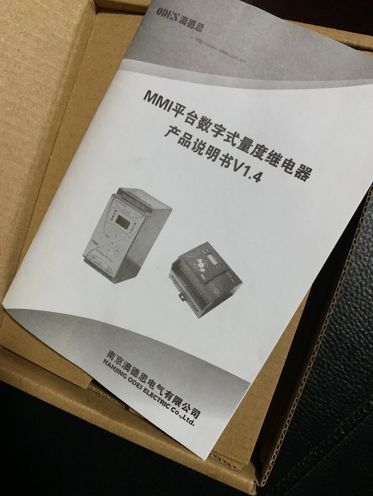

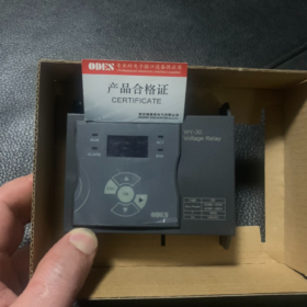
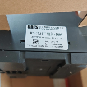

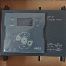
WY-30 = Digital AC Voltage Überwachungsrelais (Voltage Protection Relay)
Marke: ODEN (AoDesi / Xieao Intelligent)
Positionierung: Power system protective relay, DIN-Schienenmontage, equipped with LCD display, supports overvoltage / undervoltage monitoring and adjustable time delay setting.
Modellkodierungsregel (WY-XXAX□)
WY: Digital Voltage Relay
3: EMG32 hardware platform (WY-30 series)
1: Over-element (Overvoltage Relay)
5: Under-element (Undervoltage Relay)
A: Measuring voltage: 100 VAC (widely used for PT secondary circuits)
C: Measuring voltage: 400 VAC
Letzte Ziffer 1 / 4: 1=Single-phase; 4=Dreiphasig
Common complete models:
WY-31A1 (Single-phase Overvoltage), WY-35A1 (Single-phase Undervoltage), WY-31A4 (Three-phase Overvoltage), WY-35A4 (Three-phase Undervoltage)
Wichtigste technische Spezifikationen
- Measuring Circuit
Rated input: 100 VAC / 400 VAC; 50 Hz (60 Hz available on request)
Stromverbrauch: ≤0.5 VA
- Hilfsstromversorgung (Wide-range universal)
AC 85~265 V / DC 88~370 V
- Ausgangskontakte
2 Sätze von Wechselkontakten (2DPDT)
Kontaktbewertung: 6 A / 250 VAC; 6 A / 30 VDC
- Adjustable Setting Range
Betriebsspannung: Stufenlos einstellbar
Operating time delay: 0~10 s (extendable)
- Montage
Standard DIN35 rail mounting
Gesamtdimension: 96(L) ×90(W) ×65.3(H) mm
- EMV-Ebene: Klasse IV, suitable for substation and auxiliary power switchgear
Hauptfunktionen
Real-time single-phase / three-phase AC voltage monitoring with LCD voltage readout
Überspannungsschutz, undervoltage blocking
PT loss-of-voltage alarm, busbar voltage supervision
Time delay anti-disturbance function to avoid maloperation caused by transient fluctuations
Parameter password lock to prevent unauthorized modification
ACT operation indicator for fault phase indication
Typische Anwendungsszenarien
Generator and transformer protection panels
Hoch & low voltage switchgear, auxiliary power systems
PT voltage circuit supervision and loss-of-voltage alarming
Voltage protection for photovoltaic and wind power grid connection
AC voltage monitoring matched with DC systems in substations
Peer Products within the Same Series
WY-30: Voltage Relay (subject model)
WL-30: Current Monitoring Relay
WT Series: Synchronism Check Relay
Accuracy Specifications for ODES WY-30 Series Voltage Relay
- Genauigkeit der Spannungsmessung
Voltage measurement error: ±3 % (relative to rated input voltage Un)
Applicable to all models: WY-31A1 / WY-35A4 / WY-31C4 and other WY-30 variants
- Operating Time Delay Accuracy
Delay setting range: 0 ms~9999 ms
Time delay error: ±(1% of set value + 60 MS)
- Other Key Indicators
Reset ratio: Overvoltage type = 0.9; Undervoltage type = 1.1 (customizable upon special request)
Eingabespezifikation: 100 VAC / 200 VAC / 400 VAC, 50 Hz
Betriebstemperaturbereich: -40℃~+70℃; accuracy indicators remain valid within this range
Ergänzende Hinweise
- This device is a protective monitoring component, not a metering-grade instrument. With protection-class accuracy of ±3%, it meets standard requirements for auxiliary power supervision, PT circuit monitoring and grid connection voltage protection.
- If higher accuracy (Klasse 0.5 / Klasse 0.2 Dosierung) is required on site, multi-function power meters shall be adopted. WY-30 readings cannot be used for energy settlement measurement.
Operating Principle of ODES WY-30 Digital Voltage Monitoring Relay
The WY-30 is a MCU-based sampling digital AC voltage monitoring & protective relay. Its core function: continuously sample AC voltage, compare measured value against preset thresholds, and drive relay contact output when conditions are satisfied to realize overvoltage, undervoltage and PT loss-of-voltage monitoring.
- Hardware Signal Flow
- Voltage Input Circuit
External single-phase / three-phase AC voltage (100 VAC PT secondary or 400 VAC bus voltage) is connected to measurement terminals.
A built-in miniature precision voltage transformer isolates and steps down high-voltage AC signals into low-level signals, achieving electrical isolation between strong and weak circuits to protect the main control circuit.
- Signal Conditioning Circuit
The stepped-down sinusoidal AC signal undergoes filtering → impedance matching → offset rectification, converted into continuous analog voltage waveform suitable for MCU ADC sampling.
- MCU Main Control Unit (Kern)
Equipped with high-speed ADC; periodically samples instantaneous AC voltage values.
Built-in software algorithm calculates True RMS (Root Mean Square) Wechselspannung, which is immune to mild waveform distortion.
⚠️ Key feature: Adopts RMS calculation instead of simple peak conversion, applicable to distorted power grids such as auxiliary power systems and renewable energy grid connections.
- Parameter Storage & Mensch-Maschine-Schnittstelle
LCD screen displays real-time bus voltage;
Users configure overvoltage threshold, undervoltage threshold, operating delay and loss-of-voltage criteria via keypad. Parameters are stored in non-volatile memory, retained after power failure, and support password locking.
- Logic Judgment & Schutzlogik
MCU continuously compares measured voltage with user-defined operating value in cycles.
WY-31xx (Overvoltage Type)
Measured voltage ≥ Overvoltage setting → timer starts;
If fault persists upon delay expiry → relay actuates;
Voltage drops below reset value → relay automatically resets.
WY-35xx (Undervoltage Type)
Measured voltage ≤ Undervoltage setting → timer starts;
If undervoltage condition remains after delay → contact actuates;
Voltage rises above reset threshold → automatic reset.
Factory default reset ratio: Overvoltage = 0.9; Undervoltage = 1.1
- Relay Output Circuit
MCU transmits low-level driving signal to control on-board electromagnetic relay (2 Sätze von Wechselkontakten).
Passive contacts are wired to external control circuits for alarm, tripping and interlock.
- Vollständiger Betriebsablauf (Undervoltage Protection Example)
- Normaler Betrieb: Voltage stays within threshold range → relay remains at normal de-energized status;
- Bus voltage drops below undervoltage setting;
- Internal timer is triggered (to avoid maloperation caused by instantaneous voltage dip);
- If voltage recovers during delay period → timer resets, no operation;
- Undervoltage persists after delay expires → relay contact switches state to trigger external alarm or tripping command;
- Voltage recovers above reset value → relay automatically resets.
III. Built-in PT Loss-of-Voltage Logic (Standard Feature for Three-phase Models)
Three-phase variants implement phase loss judgment logic:
When one or multiple phases detect near-zero voltage while the remaining phases show normal voltage, the relay identifies this condition as PT circuit break / loss of voltage. Independent time delay and output logic can be configured to distinguish genuine busbar undervoltage from voltage circuit failure, preventing protection maloperation.
- Auxiliary Power Supply Mechanism
Device operating supply: AC 85~265 V / DC 88~370V wide-range input.
Internal power module generates multiple stabilized DC supplies for MCU, sampling circuit, display and relay drive.
Wichtig: Measuring voltage circuit and auxiliary power circuit are mutually independent. Powered relay does not guarantee valid voltage measurement.
- Principle Summary (Directly usable in technical proposals)
The ODES WY-30 voltage relay samples AC bus voltage via built-in isolating transformer and calculates true RMS voltage through ADC sampling. The microcontroller continuously compares measured voltage with configured thresholds with time delay anti-chatter logic. When overvoltage, undervoltage or PT loss-of-voltage faults occur, passive relay contacts are activated to output switching signals for voltage abnormality monitoring, alarming and interlock protection. It is widely applied in switchgear auxiliary power systems, PT secondary circuits and voltage monitoring for distributed generation grid connection.





NH42-63-318x560.png "Automatische Transferschalter vom Typ CHINT PC (ATS)NH42-63/4SZ")



