contactor,cortacircuitos,sensor,Codificador,SOCIEDAD ANÓNIMA,Convertidor





AVP-63 Single-phase Adjustable Dual-display Auto-reset Over/Under Voltaje + Protector de sobrecorriente
Nota: AVP-63 is a general model, not exclusive to one brand. Many electrical manufacturers in China produce this same design. It is a popular export DIN rail protection module.
Tipo: Single-phase 2P, Montaje en carril DIN, dual digital display (Voltaje + actual), adjustable parameters, auto-reset protector
Funciones: Protección contra sobretensión, protección contra subtensión, overload overcurrent protection, power restoration delay. It automatically closes after voltage returns to normal, no manual reset required.
Especificaciones técnicas estándar (Mainstream Version)
Tensión nominal: CA 230 V. / 50Hz (compatible with 220V mains)
Corriente nominal: Continuously adjustable from 1~80A, default 63A
Overvoltage Threshold: Adjustable 230~300V (factory default commonly 280V)
Undervoltage Threshold: Adjustable 140~210V (factory default commonly 160/170V)
Restoration Delay: Adjustable 1~400s, predeterminado 30s
Consumo de energía: ≤2W
Dimensiones generales: Aprox.. 85×36×66 mm
Montaje: 35carril DIN estándar mm
Certificaciones: Most versions carry CE; some domestic units can obtain CCC
Código HS: 8536500000 (switching protection electrical apparatus)
Principio de funcionamiento
- When voltage/current exceeds the set threshold → trip and cut off power immediately
- Fault cleared and voltage back within normal range → wait for configured delay then auto-close to restore power
- Dual screens display real-time voltage and output current; panel keys SET + UP/DOWN for parameter configuration
Escenarios de aplicación típicos
Residential power distribution, photovoltaic grid-tie side, small industrial control, communication power supplies, equipo comercial, overseas single-phase power distribution projects (widely used in Southeast Asia and Central Asia)
Selección de modelo & Notas de reemplazo
Domestic well-known auto-reset over/under voltage protectors (without current display): alternatives from Delixi, chint, Tengen are available, but they lack current monitoring and adjustable dual-display interface
When replacing AVP-63, confirm three priorities: ① whether overcurrent protection is required ② whether local digital parameter setting is needed ③ whether auto-reset delay is mandatory
Firmware parameter ranges differ between manufacturers (a few versions support undervoltage limit down to 80V). Verify datasheet before purchase.
Fallos comunes
No display after power-up: live/neutral reversed, falta tensión de alimentación
Frecuentes disparos en falso: thresholds set too close to normal voltage, large line surges
No power restoration after fault clears: delay set to maximum value, internal relay damaged
AVP-63 Panel Key Operation Steps (Mainstream Version, COLOCAR / ▲ / ▼ / Power Key)
Panel: Upper screen = Voltage V, Lower screen = Current A; 4 llaves: COLOCAR, ▲ Up, ▼ Down, ⏻ Manual on/off key
⚠️ Safety Warning: Risk of electric shock during live commissioning; isolate upstream circuit breaker before maintenance
- Basic Operation Procedure
- Standby State: After power on, dual screens show real-time voltage and current
- Enter Parameter Menu: Long press SET for 3 artículos de segunda clase, screen shows R1 (parameter code) to enter setting mode
- Switch Parameter Items: Short press SET to cycle through R1~R12
- Modify Value: When the target parameter flashes, press ▲ to increase, ▼ to decrease
- Confirm and Next Item: Short press SET to save and jump to next parameter
- Exit Setting: After all adjustments, long press SET for 3 seconds to exit, or wait 8~10 seconds for auto-save and exit
- Manual Close / Viaje: Short press ⏻ power key to directly control output on/off, without modifying protection thresholds
- Parameter Sequence (R1~R12, General Domestic Firmware)
| Código de parámetro | Nombre del parámetro | Adjustable Range | Valor predeterminado |
| R1 | Power-on Delay (waiting time before closing after energization) | 1~500s | 10s |
| R2 | Overvoltage Trip Value | 230~300V | 270V |
| R3 | Overvoltage Recovery Value (voltage must drop below this to enable reset) | 225~295V | 265V |
| R4 | Overvoltage Restoration Delay | 1~500s | 30s |
| R5 | Overvoltage Action Delay (delay before tripping once overvoltage threshold is exceeded) | 0.1~ 30 años | 1s |
| R6 | Undervoltage Trip Value | 140~210V | 170V |
| R7 | Undervoltage Recovery Value | 145~215V | 175V |
| R8 | Undervoltage Restoration Delay | 1~500s | 30s |
| R9 | Undervoltage Action Delay | 0.1~ 30 años | 1s |
| R10 | Overcurrent Protection Value | 1~63A | 63A |
| R11 | Overcurrent Restoration Delay | 1~500s | 30s |
| R12 | Overcurrent Action Delay | 0.1~ 30 años | 1s |
- Funciones adicionales (Password Lock on Some Versions)
Password item P19 appears at the end of menu; contraseña predeterminada 112. If password mismatch, only view access, modification locked
When locked, long pressing SET only allows browsing parameters; ingresar 112 to unlock editing
Some units support auto-reset toggle: P16, Con = Auto Reset, OFF = Manual Close (must press power key to restore after fault)
- Fault Code Indication
OL: Overcurrent Trip
OH: Overvoltage Trip
UL: Disparo por subtensión
After fault, power restores automatically when voltage/current returns to normal and delay expires. If manual mode is enabled, press ⏻ key to restore power.
- Quick Setting Example (General Household 220V)
- Long press SET for 3s to enter menu
- R2 Overvoltage: 270V; R6 Undervoltage: 170V
- R10 Overcurrent: 63A
- R1 Power-on delay 10s, R4/R8/R11 restoration delay 30s
- Long press SET to exit, configuration completed
- Setting Troubleshooting
- SET no response: panel locked by password, faulty key, tensión de alimentación insuficiente
- Settings not saved: do not cut power before exit; wait for auto-exit or long press SET to confirm
- Tropiezos frecuentes: action delay R5/R9/R12 set too short, or thresholds set too close to normal voltage
Advertencia de seguridad: Risk of electric shock during live testing. Professional function test is recommended using adjustable AC power supply (variac). Do NOT forcibly raise mains voltage for overvoltage test.
Testing sequence: Inspección visual & power-on self-test → Display & manual switching test → Parameter read-write verification → Protection function validation → Long-term load stability test
- Initial Power-on Check (On-site, No Special Instrument Required)
- Encendido, screens light up; upper screen shows voltage, lower screen shows current
- Use multimeter to measure input IN voltage, compare with protector reading: deviation normally ≤±5V. Larger deviation indicates faulty sampling circuit
- Measure output OUT with multimeter:
Normal closed state: IN and OUT voltage nearly equal
Tripped by protection: 0V at OUT
- Definición del indicador:
POWER green ON: unit power supply normal
V red ON: Overvoltage fault (OH)
<V red ON: Undervoltage fault (UL)
A red ON: Overcurrent fault (OL)
- Manual switching test: short press ⏻ key, output turns on/off accordingly, key response normal
Abnormal conditions: black screen after power-up, garbled flashing, keys unresponsive, green power light ON but no output → likely damaged
- Parameter Read-write Verification (Check Mainboard & Memory Integrity)
- Long press SET for 3s to enter menu, can cycle through R1~R12 normally
- Values can be modified; after saving and exiting, re-enter menu to confirm parameters retained
- If password lock activated, modification allowed after correct password input; locked mode only supports viewing, which is normal
Anormal: parameters revert after exit, menu jumps randomly → firmware / falla de memoria
- Protection Function Validation (Precise Test, Variac Required)
1) Overvoltage Protection Test
- Connect adjustable power supply to AVP-63 input
- Set R2 overvoltage trip value to 270V
- Slowly increase input voltage. After exceeding threshold plus action delay, protector trips, shows OH, >V red light ON, output cuts off
- Reduce voltage below R3 overvoltage recovery value, wait for restoration delay, auto-close and restore power
2) Undervoltage Protection Test
- Set R6 undervoltage trip value to 170V
- Slowly reduce input voltage. Below threshold plus action delay, protector trips, shows UL, <V red light ON
- Raise voltage above R7 undervoltage recovery value, power restores automatically after delay
3) Overcurrent Protection Test (Adjustable Load / Current Source Required)
- Set R10 overcurrent value e.g. 20A
- Gradually increase load current. When current exceeds threshold plus action delay, protector trips, shows OL, >A red light ON
- Current drops below recovery level, power restores automatically after delay
Acceptance criteria: actual action threshold matches configured value; no missing trip or spurious trip. Auto-restore after fault cleared and delay completed.
- Simple Field Test Without Variac (Emergency Site Check)
- Power cycle the unit, observe power-on delay: it closes after R1 configured time, not instantly
- Run under rated load for a period: current reading stable, no overheating, no random tripping
- Apply mild overload for a short time (safety priority) to verify OL trigger
⚠️ Do NOT test by forcing mains voltage high, risk of equipment burnout
- Long-term Stability & Inspección visual
No bulging, burn marks on enclosure; terminal blocks no discoloration or overheating
Readings stable under load, no random fault codes
No frequent false tripping: if OH/UL alarms persist with stable mains, either sensitive threshold setting or faulty sampling board
- Quick Diagnosis Summary Table
| Fenómeno | Conclusión |
| Power-on display normal, keys responsive, input/output voltage consistent, parameters saved | Basically functional |
| Trips at set thresholds, auto-restores after delay | Fully functional |
| Display normal, no output even after manual close | Internal relay failed / soldado |
| Random OH/UL alarms with normal voltage, tropezones frecuentes | Sampling circuit fault or improper threshold setting |
| pantalla negra, garbled display, keys fully unresponsive | Mainboard damaged |
| Modified parameters cannot be saved | Memory chip failure |
- Nota complementaria
AVP-63 cannot replace circuit breaker for short-circuit protection. It only provides over/under voltage and overload protection. Short-circuit protection must be provided by upstream circuit breaker. Upstream breaker must be retained as backup during testing.


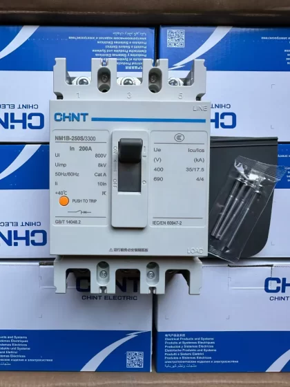
NH42-63-318x560.png "Interruptores de transferencia automática tipo PC CHINT (ATS)NH42-63/4SZ")