 contactor,cortacircuitos,sensor,Codificador,SOCIEDAD ANÓNIMA,Convertidor


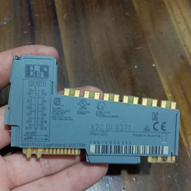
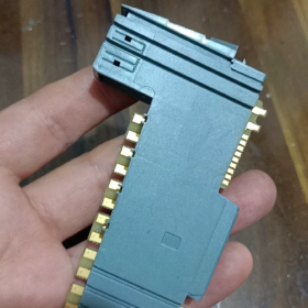
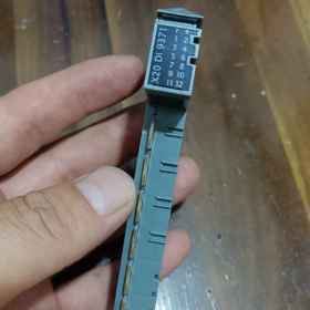
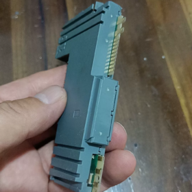
Explicación del código del modelo
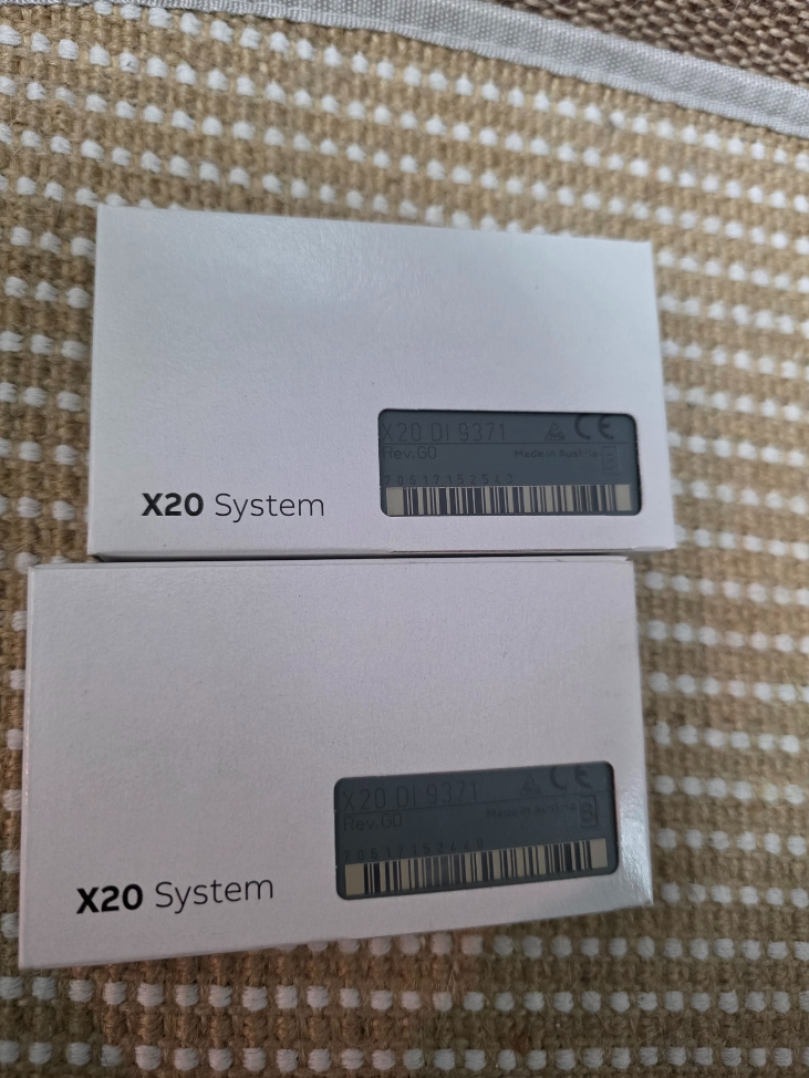
X20DI9371
X20: Plataforma del sistema de E/S distribuidas X20
DE: Entrada digital
9371: Código de especificación del módulo
- Electricidad principal & Especificaciones de hardware
| Artículo | Especificación |
| Número de canales | 16 entradas digitales |
| Tipo de entrada | 24 hundimiento de VCC / compatible con abastecimiento, CEI 61131-2 Tipo 3 |
| Voltaje de entrada nominal | 24 VCC (rango de operación: 18~30 VCC) |
| Impedancia de entrada | Aprox.. 3.9 kΩ |
| Lógica activada (1) Límite | ≥11 VCC |
| Lógica apagada (0) Límite | ≤5 VCC |
| Corriente de entrada por canal | ≈6 mA a 24 VCC |
| Retraso de respuesta | Típico 0.1 EM; filtro de hardware configurable: 0.1 / 0.5 / 3 / 15 EM (parametrización mediante software) |
| Método de aislamiento | Aislamiento grupal: 4 canales por grupo, total 4 grupos aislados |
| Tensión de aislamiento entre grupos.: 500 VACACIONES | |
| Interfaz de autobús | Bus de sistema interno X20 Link |
| Indicación de estado | LED independiente para cada canal; LED de alimentación del módulo |
| Consumo de energía | tipo. 1.8 W. |
- Mecánico & Especificaciones ambientales
Montaje: Estándar 35 carril DIN mm, instalación horizontal
Dimensiones: W. 40 mm × alto 100 mm × profundidad 76.5 milímetros
Temperatura de funcionamiento: -20 ℃ ~ +60 ℃ (dentro del gabinete de control)
Almacenamiento / Temperatura de transporte: -40 ℃ ~ +85 ℃
Clase de protección: IP20 (solo para instalación en gabinete)
Certificaciones: CE, UL 508, Certificación marina GL, compatible con EN 61000 Estándares industriales EMC
- Estructura interna & Definición de terminal
16 canales divididos en 4 grupos aislados:
Grupo1: CH0~CH3
Grupo2: CH4~CH7
grupo3: CH8~CH11
grupo4: CH12~CH15
⚠️ Regla de cableado importante: El terminal común de un grupo aislado debe compartir el mismo 24 polaridad V; NO conectar por separado, no referenciado 24 Fuentes de alimentación en V a diferentes grupos aislados, De lo contrario, la diferencia de potencial puede dañar el circuito de aislamiento..
Configuraciones de cableado
- Entrada de abastecimiento (PNP Sensor)
La salida del sensor se conecta al terminal DI del módulo; Los terminales comunes del módulo se conectan a 0V.(Tierra)
- Entrada de hundimiento (Sensor NPN)
El terminal de alimentación del sensor se conecta a 24 V+, salida del sensor al terminal DI; Los terminales comunes del módulo se conectan a +24 V.
- Principio de funcionamiento
Señal de sensor digital externo → Circuito de filtro de hardware RC frontal → Grupo de aislamiento de optoacoplador → Circuito de conformación de señal → Chip de comunicación de bus X20
El controlador lee cíclicamente el estado del canal a través de la CPU X2X/X20. Los parámetros de tiempo de filtrado se pueden configurar en Automation Studio para suprimir el rebote de contactos y los pulsos de interferencia generados por los inversores..
- Información del software
Software de programación: Estudio de automatización 4.0 y todas las versiones posteriores son compatibles
Identificación de hardware: Biblioteca incorporada de descripción del dispositivo X20 estándar, no se requiere ningún archivo GSD adicional
Imagen de proceso: Mapeo automático de direcciones de canales; forzado de señal de soporte & monitoreo de señal en línea
Funciones admitidas: Diagnóstico de canal (sin detección de rotura de cable, X20DI9371 no admite el diagnóstico de rotura de cable)
- Comparación de modelos & Reemplazo compatible
Comparación con modelos similares de la serie X20
| Modelo | Canales | Característica de aislamiento | Características |
| X20DI9371 | 16DE | 4 canales por grupo aislado | Módulo estándar de uso general, ampliamente utilizado en proyectos |
| X20DI9372 | 16DE | Aislamiento galvánico individual de canal completo | Para entornos de alta interferencia, multiseñales con diferentes potenciales |
| X20DI4371 | 4DE | 4 canales por grupo aislado | Módulo compacto para puntos de E/S limitados |
✅ Condiciones de reemplazo directo
Si X20DI9371 se utiliza en proyectos existentes:
Actualice para obtener un mayor rendimiento antiinterferencias: X20DI9372 (compatible con asignación de pines, no se requiere modificación del programa, cableado totalmente intercambiable; la única diferencia es el rendimiento de aislamiento mejorado)
❌ No directamente intercambiables: X20DI4371 tiene diferente cantidad de canales y disposición de terminales de la unidad base
- Escenarios de aplicación típicos
Máquinas herramienta, maquinaria de embalaje, transportadores de manipulación de materiales, goma & equipo de plastico, tratamiento de agua, líneas de producción de automatización general
Adquisición de señal: Interruptores de proximidad, sensores fotoeléctricos, interruptores de límite, pulsadores, contactos de relé pasivos
- Pautas de instalación & Solución de problemas
Prohibiciones estrictas
- Nunca aplique voltaje superior a 30 VCC, dañará permanentemente los circuitos de entrada
- No conecte dos cables de tierra no comunes. 24 Fuentes de alimentación en V a diferentes grupos aislados
- Evite el tendido paralelo de cables de señal y cables de alimentación (fuertes interferencias eléctricas provocan señales parpadeantes)
Fallos comunes
- LED de canal siempre encendido: Cable de señal en cortocircuito a tierra.; fuente de alimentación anormal para el sensor PNP
- Fluctuación intermitente de señal: Interferencia electromagnética grave → aumentar el tiempo de filtrado del hardware; comprobar blindaje & toma de tierra
- Todos los canales de un grupo sin señal: Pérdida de suministro eléctrico al terminal común del grupo correspondiente.
- Unidades básicas compatibles
Base estándar: X20BM01 (base de terminal de tornillo)
Base opcional: X20BM11 (terminal de conexión rápida con jaula de resorte)
La base debe pedirse por separado; La base terminal NO está incluida con el módulo.!
Asignación de pines del terminal X20DI9371
Bases compatibles: X20BM01 (tornillo) / X20BM11 (terminal de resorte)
16 canales divididos en 4 grupos aislados galvánicamente (4 canales cada uno)
Grupo1: CH0~CH3~Grupo2: CH4~CH7|Grupo3: CH8~CH11|Grupo4: CH12~CH15
Secuencia de terminales (De arriba a abajo en la base)
Grupo 1 (CH0~CH3)
1: DI0
2: DI1
3: DI2
4: DI3
5: COM0 (Terminal común para el Grupo 1)
Grupo 2 (CH4~CH7)
6: DI4
7: DI5
8: DI6
9: DI7
10: COM1 (Terminal común para el Grupo 2)
Grupo 3 (CH8~CH11)
11: DI8
12: DI9
13: DI10
14: DI11
15: COM2 (Terminal común para el Grupo 3)
Grupo 4 (CH12~CH15)
16: DI12
17: DI13
18: DI14
19: DI15
20: COM3 (Terminal común para el Grupo 4)
Resumen de especificaciones de cableado
- Sensor PNP (Entrada de abastecimiento, Estándar de la industria)
Todos COM0/COM1/COM2/COM3 → conectar a 24 VCC 0V(Tierra)
Cable de señal del sensor a DIx, terminal positivo del sensor a 24V+
- Sensor NPN (Entrada de hundimiento)
Todos COM0/COM1/COM2/COM3 → conectar a +24 VCC
Cable de señal del sensor a DIx, terminal negativo del sensor a 0V
⚠️ Importante: COM0/COM1/COM2/COM3 están aislados galvánicamente entre sí.
No conecte diferentes terminales COM a fuentes de alimentación con potencial de tierra no compartido!
Pasos para configurar el filtro de entrada en Automation Studio
- Ubique X20DI9371 en el árbol del proyecto y haga doble clic para abrir la ventana de configuración
- Nombre del parámetro: Tiempo de filtro de entrada
Opciones seleccionables:
0.1 EM (respuesta rápida, para señales de alta velocidad)
0.5 EM
3 EM (Recomendado para pulsadores normales. & interruptores de proximidad)
15 EM (entorno de fuerte interferencia, suprimir el rebote de contacto)
- Descargar proyecto; Los parámetros entran en vigor inmediatamente sin ciclo de energía.



NH42-63-318x560.png "Interruptores de transferencia automática tipo PC CHINT (ATS)NH42-63/4SZ")



