 contactor,cortacircuitos,sensor,Codificador,SOCIEDAD ANÓNIMA,Convertidor

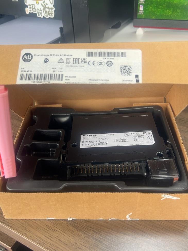

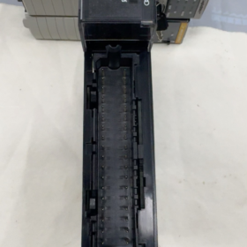
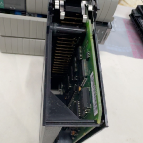
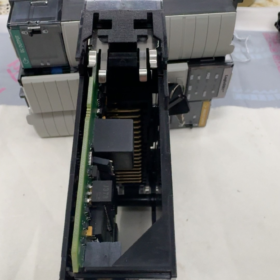
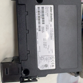
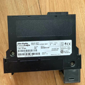
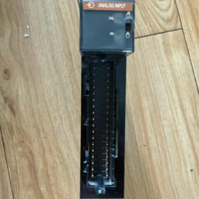
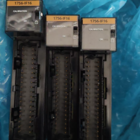
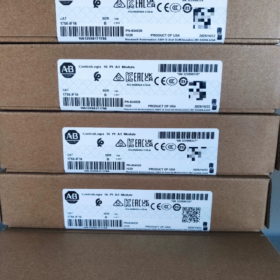
Desglose del código del modelo
1756-IF16
1756: ControlLogix rack series I/O
SI: Entrada analógica (Voltaje/Corriente)
16: 16 canales
Suffix Variants
1756-IF16: Versión estándar
1756-IF16K: Conformal coated version (para alta humedad, ambientes polvorientos y corrosivos)
⚠️ Importante: No isolation between channels! Only reinforced insulation of 250 VAC exists between the backplane and field signals. All channels share a common ground, bringing risks of common-mode interference among multiple signals.
- Key Hardware Specifications
| Artículo | Parámetro |
| Channel Modes | 16 single-ended channels / 8 differential channels / 4 differential channels (high-speed mode) |
| Supported Signal Ranges | ±10.25 V, 0~10.25 V, 0~5.125 V, 0~20.5 mA (4~20 mA configurable via software) |
| ADC Resolution | 16-poco; ±10 V range: 15 data bits plus sign bit |
| Impedancia de entrada (Voltaje) | >10 MΩ |
| Current Loop Resistor | Incorporado 249 Oh (activated by software for corresponding channels; no external 250 Ω resistor required) |
| Exactitud (25℃) | Voltaje: ±0.05% FS; Actual: ±0.15% FS |
| Minimum Scan Time | 16 ms for all 16 canales; 50 Hz / 60 Hz filter configurable |
| Backplane Power Consumption | 150 mA @ 5.1 VCC; 65 mA @ 24 VCC; Total power consumption: 2.33 W. |
| Terminal Base (RTB, 36-alfiler) | 1756-TBCH (spring cage) / 1756-TBS6H (tipo de tornillo) |
| Clasificación de aislamiento | Reinforced isolation 250 V continuous between field signals and backplane; Sin aislamiento entre canales |
| Temperatura de funcionamiento | 0~+60℃; Temperatura de almacenamiento: -40~+85℃ |
| Humedad | 5%~95% non-condensing; IP20 (cabinet installation only) |
- Definición de cableado de terminales (Differential Channel Groups)
The module contains 8 differential channel groups; each group corresponds to two single-ended channels:
| Differential Channel | Positive (IN+) | Negative (IN-) | Return RTN | Applicable Sensors |
| Ch0 | IN0 | IN1 | RTN0 | 4~20 mA pressure/flow transmitters, voltage sensors |
| Ch1 | IN2 | IN3 | RTN2 | |
| Ch2 | IN4 | IN5 | RTN4 | |
| Ch3 | IN6 | IN7 | RTN6 | |
| Ch4 | IN8 | IN9 | RTN8 | |
| Ch5 | IN10 | IN11 | RTN10 | |
| Ch6 | IN12 | IN13 | RTN12 | |
| Ch7 | IN14 | IN15 | RTN14 |
Pautas de cableado
- 2-wire 4~20 mA Transmitter: INx+ → Transmitter positive; RTNx → Transmitter negative. Set channel to Current mode in software; the module automatically engages the internal 249 Ω resistor. Do NOT add an external 250 Ω resistor. Parallel resistors will halve the measurement range.
- 0~10 V Voltage Signal: INx+ connects to positive signal wire; INx-/RTN connects to signal ground. The internal 249 Ω resistor is disabled under voltage mode.
- Mixed channel configuration: Voltage and current channels can coexist on one module; each channel is configurable independently in software.
- Cable specification: Shielded twisted pair. Ground the shield at cabinet side only; avoid two-end grounding to prevent ground loop interference.
- Studio 5000 Guía de configuración
- Module addition: Select 1756-IF16; minimum firmware version V21 or higher
- Channel parameters:
Tipo de entrada: Voltaje / Actual
Filter: 50 Hz (for China power grid)
Formato de datos: Scaled (engineering unit) / Raw (raw value)
- Recommended scaling for 4~20 mA:
4 mA → 0; 20 mA → 32760 (common setting)
- Diagnostic functions: Open wire detection, over-range and under-range alarm.
- Comparación de series & Selección alternativa
| Modelo | Conteo de canales | Inter-channel Isolation | HART Support | Escenarios de aplicación |
| 1756‑IF16 | 16 AI | ❌ No isolation | ❌ No | Large quantities of standard 4~20 mA / 0~10 V signals, proyectos sensibles a los costos |
| 1756‑IF8 | 8 AI | ❌ No isolation | ❌ No | Projects requiring fewer analog points |
| 1756‑IF6I | 6 AI | ✅ Independent channel isolation | ❌ No | Sites with ground potential differences and severe interference between multiple signals |
| 1756‑IF16H | 16 AI | ❌ No isolation | ✅ Yes | HART smart transmitters (device diagnostics accessible) |
⚠️ Consejo de selección: Avoid 1756-IF16 near inverters, high-power motors or systems with remotely grounded sensors. Ground loops will cause signal drift. Prefer isolated 1756-IF6I instead.
- Fallos comunes & Solución de problemas
- 4~20 mA reading shows half scale only
Root cause: Externo 250 Ω resistor fitted while channel set to Current mode. Solución: Remove external sampling resistor.
- Fluctuating or drifting measured values
Root cause: Poor shield wiring, multi-point grounding, excessive common-mode voltage. Solución: Adopt differential wiring and single-point grounding.
- False open wire alarm
Check transmitter power supply, loose terminals and cable damage.
- Flashing OK indicator on module
Verify backplane power; confirm RTB terminal base is fully locked; match electronic key setting.
- Strict Prohibited Operations (Líneas rojas)
- Do not feed field signals exceeding 24 VCC; risk of front-end channel burnout.
- Do not connect data loggers or other loads in parallel to current input channels.
- Never hot-swap the RTB terminal base under power; this may permanently damage the module.
- Do not connect sensors with different ground potentials to the same 1756-IF16 module under high electromagnetic interference.
- Industrias de aplicación típicas
Tratamiento de agua, aceite & gas, metalurgia, maquinaria de embalaje, cement production lines. Used for acquisition of pressure, nivel de liquido, temperature and flow signals from 4~20 mA transmitters and potentiometer/voltage sensors.
Si es necesario, puedo proporcionar:
- Complete Studio 5000 configuration template (scaling parameters, tag examples)
- Text schematic for standard 4~20 mA transmitter wiring
- Detailed comparison table between 1756-IF16 and 1756-IF16H
Studio 5000 Configuration Template for 1756-IF16
- Basic Module Settings
Modelo: 1756-IF16
Minimum Firmware Version: V21.011
Electronic Key: Recommended `Compatible Module`; select `Exact Match` for new projects
Rack Slot: Configure as required (Slot X)
- Global Module Parameters
- Filter Frequency: 50 Hz (Chinese power grid)
- Formato de datos: `Scaled` (engineering unit, recomendado)
- Sampling Mode: Standard sampling (por defecto)
- Channel Fault Action: `Hold Last Value`
- Standard Single-Channel Configuration (4~20 mA Transmitter)
| Parámetro | Configuración | Descripción |
| Tipo de entrada | Actual | Current mode activates internal 249 惟 sampling resistor |
| Open Wire Detection | Enable | Activate cable break diagnosis |
| Low Scale | 4000 | Raw value corresponding to 4 mamá |
| High Scale | 20000 | Raw value corresponding to 20 mamá |
Raw value range: 4 mA = 4000; 20 mA = 20000
Scaling Example (Liquid Level 0~10 m)
Scaled Min: 0.0
Scaled Max: 10.0
Lógica: 4 mA → 0 metro, 20 mA → 10 metro
- Structured Tag Template
TAG_NAME
.RawData // Raw ADC conversion value
.ScaledData // Converted engineering floating-point value
.Falla // Channel fault bit
.OpenWire // Cable break alarm
.OverRange // Upper limit exceeded
.UnderRange // Below lower limit
- Optional Ladder Logic Conversion Formula
Manual programming is unnecessary if Scaled mode is enabled. For Raw mode:
ScaledValue = ((Raw 4000) / (20000 4000)) (MaxEng MinEng) + MinEng;
Text Wiring Diagram for 4~20 mA Two-Wire Transmitter
Single-ended Wiring (Común)
24V DC+ → Transmitter positive
Transmitter negative → RTNx terminal of 1756-IF16
INx+ terminal → Transmitter negative
✅ Key reminder: No external 250 Ω sampling resistor
Differential Wiring (Anti-interference Preferred)
Transmitter negative → RTNx
Transmitter signal wire → INx+
Signal reference ground → INx-
Supplementary Practical Tips
- Mixed configuration supported: Some channels set as Current, others as Voltage.
- For 0~10 V voltage signals, set Input Type = Voltage; interno 249 Ω resistor is disconnected.
- Open wire detection only works under Current mode; unavailable for voltage channels.
- Terminal base options: 1756-TBS6H (terminal de tornillo) / 1756-TBCH (terminal de resorte).
1756-IF16 Channel Quantity Summary
Total: 16 canales de entrada analógica
Modos de funcionamiento:
- Single-ended mode: 16 independent AI channels (Ch0~Ch15)
- Differential mode: 8 differential channel groups (2 single-ended channels form one differential channel)
Additional Key Information:
Sufijo “16” denotes channel quantity.
No isolation between channels. Isolation only exists between backplane and field circuits.
Supports 4~20 mA current and 0~10 V voltage signals.
Related Models Reference:
1756-IF8 → 8-channel analog input
1756-IF16H → 16 channels with HART protocol capability
Widely Used Industries & Application Scenarios of 1756-IF16
Basic Background
1756-IF16 is a general-purpose 16-channel non-isolated analog input module for the ControlLogix platform, compatible with 4~20 mA transmitters and 0~10 V voltage signals.
Ventajas: High channel density, cost effective.
Limitación: Sin aislamiento entre canales. Not suitable for sites with severe ground loops, strong electromagnetic interference and remotely located sensors.
Principales industrias de aplicaciones
- Tratamiento de agua / Municipal Environmental Protection (Más común)
Measured signals: Liquid level, pH, turbidity, residual chlorine, presión, flow transmitters
Escenarios: Waterworks, sewage treatment plants, sistemas de reutilización de agua, pump station clusters
Características: Dense analog points, normal interference environment, massive 4~20 mA instruments; ideal for bulk deployment of 1756-IF16.
- Aceite, Gas & Petroquímico (General Process Areas)
Measured signals: Temperatura, presión, nivel de liquido, fluir
⚠️ Nota: Safety barriers required for hazardous areas.
Select isolated 1756-IF6I for sites with remote grounding and heavy interference. 1756-IF16 can be adopted for instrument signal collection inside control rooms.
- Cemento & Building Material Production Lines
Measured signals: Kiln temperature, wind pressure, material level, weighing signal, motor bearing temperature
Escenarios: Raw material mills, rotary kilns, packaging systems; signal acquisition in central control rooms.
- Alimento, Bebida & Industria Farmacéutica (Ordinary Sections of Clean Workshops)
Measured signals: Tank liquid level, temperatura, presión, fluir
Suitable for low-interference clean workshops. Select conformal coated 1756-IF16K for sterilization areas and corrosive environments.
- Heating Systems & Auxiliary Power Plant Systems
Measured signals: Boiler water temperature, steam pressure, fluir, water tank level
Applicable projects: Auxiliary control systems of thermal power plants, heat exchange stations for heating pipe networks.
Precaución: Avoid installation close to boilers with strong vibration and inverters.
- Embalaje, Inyección de plástico & Maquinaria de caucho
Measured signals: Sensores de presión, transmisores de temperatura, displacement voltage signals
Ventaja: Moderate I/O quantity for machine integration; ControlLogix is widely adopted for high-end production lines.
- Industria metalúrgica (Auxiliary Systems for Hot & Cold Rolling)
Only recommended for secondary instrument signal collection in remote control rooms.
Do not use 1756-IF16 near rolling mills with high-power inverters; ground loops easily cause analog signal drift.
- Almacenamiento Logístico & Bulk Port Conveying Systems
Belt scales, silo level measurement, dust removal system pressure monitoring.
Suitable Working Conditions for 1756-IF16
✅ All signals concentrated in one cabinet with shared reference ground and negligible ground potential difference
✅ Large volume of standard 4~20 mA / 0~10 V signals, pursuing high channel density and cost control
✅ Standard construction: shielded twisted-pair cables with single-point cabinet grounding
Escenarios inadecuados (Selección de líneas rojas)
❌ Areas adjacent to inverters and high-power motors with heavy electromagnetic interference
❌ Sensors distributed across different buildings with ground potential differences (prone to measurement drift)
❌ Projects requiring electrical isolation between channels (replace with 1756-IF6I)
❌ Projects requiring parameter reading and writing for HART smart transmitters (replace with 1756-IF16H)



NH42-63-318x560.png "Interruptores de transferencia automática tipo PC CHINT (ATS)NH42-63/4SZ")



