 contactor,cortacircuitos,sensor,Codificador,SOCIEDAD ANÓNIMA,Convertidor

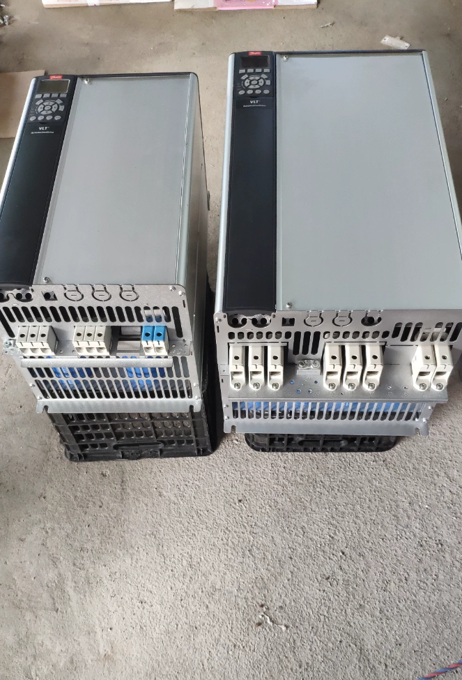

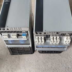
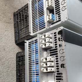
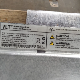
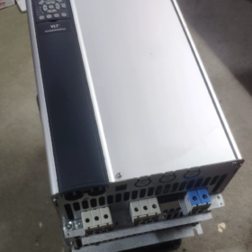
VLT AutomationDrive FC-302 de alto rendimiento y uso general Convertidor de frecuencia
Nro. de orden: 131F7151
Modelo de decodificación segmento por segmento
FC-302 P55K T5 E20 H2 B G XXXX SXXXX AXBXCXXXXDX
| Campo | Significado | Descripción |
| FC-302 | Serie de productos | Unidad de automatización VLT FC‑302, con control de movimiento, Parada segura, admite aplicaciones de tipo servo |
| P55K | Clasificación de potencia | 55 kilovatios / 75 caballos de fuerza |
| T5 | Especificación de la fuente de alimentación | 3‑fase 380‑500 VCA |
| E20 | Protección de ingreso | Marco abierto IP20, instalación montada en gabinete |
| H2 | Filtro RFI | Filtro EMC industrial clase C3 (2Segundo ambiente, uso en el piso de la fábrica) |
| B | Picador de freno | Chopper de freno incorporado, resistencia de freno conectable |
| GRAMO | Panel del operador | Panel gráfico chino LCP102 (mostrar & teclado) |
| XXXX | Recubrimiento de PCB / Opción de energía | X = PCB estándar sin recubrimiento, sin opciones de fuente de alimentación adicionales |
| SXXXX | Revisión de software | Última versión de firmware estándar de fábrica |
| HACHA | Ranura de opción A | Sin tarjeta de comunicación con ranura A (ranura A vacía; Profinet, EtherNet‑IP, etc.. se puede adaptar) |
| BX | Ranura de opción B | Sin tarjeta de expansión con ranura B |
| CX | Ranura de opción C | Tarjeta de control de movimiento MCO sin ranura C |
| DX | Ranura de opción D | Sin tarjeta opcional con ranura D |
Especificaciones eléctricas básicas
potencia nominal: 55 kilovatios
Aporte: 3-fase 380-500V CA
Corriente de salida continua: 106 A
Sobrecarga: 160 % durante 1 minuto (modo de alta sobrecarga)
Tamaño del bastidor del chasis: C4
Componentes a bordo: Reactor de enlace CC, picador de freno, Filtro RFI clase C3
Protocolo estándar: Modbus RTU; no hay tarjetas de comunicación adicionales instaladas
Función de seguridad: Terminal de hardware Safe-Stop
Temperatura ambiente: Clasificación completa a 40°C; reducción de potencia por encima de máx. 50°C
Resumen de configuración clave
✅ 55kW, 380-500 V, Marco abierto IP20
✅ Picador de freno incorporado, compatible con resistencia de freno
✅ Equipado con panel de operador gráfico LCP-102
✅ Filtro EMC industrial clase C3, reactor de enlace de CC integrado
❌ Sin beneficio / EtherNet-IP u otras tarjetas de bus de campo; se puede reequipar mediante ranuras A/B
❌ Sin tarjeta de control de movimiento MCO
Aplicaciones típicas
aficionados, zapatillas, extrusoras, transportadores, mezcladores, husillos de máquinas herramienta. Soporta vector de bucle cerrado, modos de bucle abierto y servo; adecuado para aplicaciones con energía de frenado regenerativa.
pieza de repuesto & Consejos de reemplazo
- Si no se requiere chopper de freno: cambiar B a X; el número de pedido será diferente.
- Para Profinet: opción de ajuste AL (MCA120); para EtherNet-IP: opción de ajuste AN (MCA121).
- Misma potencia sin panel: reemplaza G con X, el modelo se convierte en FC-302P55KT5E20H2BXXXXSXXXXAXBXCXXXXDX
FC-302P55KT5E20H2BGXXXXSXXXXAXBXCXXXXDX
55 kilovatios / 380-500 VIP20, chopper de freno incorporado, Filtro EMC clase C3, Panel gráfico chino LCP102; sin tarjeta de comunicación, sin tarjeta de control de movimiento MCO.
- Notas esenciales sobre cableado (apagado; Permitir un tiempo de descarga mínimo de 20 minutos para el bus de CC.)
Circuito de alimentación principal
| Terminal | Función | Observaciones |
| L1/L2/L3 | 3Entrada fase 380‑500 V | NO intercambie con terminales de motor U/V/W |
| UV/V/W | Salida del motor | Conectar al motor trifásico; cable blindado recomendado |
| BR+ / BR‑ | Resistencia de freno | Para chopper de freno incorporado; conecte la resistencia de freno aquí, NO conectar a terminales de bus de CC |
| +CC /‑CC | Bus de enlace CC | Se utiliza para sistemas de múltiples variadores de bus de CC común; dejar desconectado para funcionamiento estándar |
| educación física | Tierra protectora | Obligatoria una conexión a tierra fiable |
Sugerencia de tamaño de cable para 55kW: cable de alimentación ≥16mm²; cable motor ≥16mm²; cable de resistencia de freno ≥10mm².
Conexiones obligatorias del circuito de control (fallo o accionamiento inhibido si se ignora)
- Desconexión de par segura STO: terminal corto 12 a 37. Sin cortocircuito, La salida del inversor está inhibida.. Para circuitos de seguridad externos, contactos de seguridad de alambre en serie.
- Terminal de costa a parada 27 está activo de fábrica: si no es necesaria la parada por inercia: establecer parámetro 5-12 = 0 (sin función). Para mantener la parada por inercia: corto 12-27.
- Terminales 12/13: salida interna de +24V (máx. 200mA); terminal20 = tierra común de entrada digital.
- Entradas analógicas: 53 (0-10 tensión V); 54 (4-20 mamá). Los interruptores DIP de hardware seleccionan el voltaje / modo actual.
- Terminales 68/69: RS485 Modbus-RTU; 68 =Un, 69 =B.
Ejemplo de lógica start-stop basada en terminal
18 (DE): Comenzar (parámetro5-10=Inicio)
19 (DE): Contrarrestar (parámetro5-11=Revertir)
54: 4-20 referencia de frecuencia mA
Relé 01-02-03: configurable para ejecutar / Señalización de fallos.
Consejos prácticos: Primero encienda sin motor y verifique el estado de E/S.. Para la puesta en servicio, desacople el acoplamiento del motor y pruebe a baja velocidad.
- Procedimientos de restablecimiento de fábrica
Método 1: Inicialización recomendada (Conserva las horas de funcionamiento y la configuración de comunicación.)
- Menú principal → 14-Funciones especiales → 14-22 Modo de operación
- Seleccionar 2 Inicialización → presione OK
- Desconecte el suministro principal; Espere hasta que el panel esté completamente oscuro.; volver a aplicar energía
- A80 Aparece el mensaje informativo “Unidad inicializada” (no es una culpa); presione Reiniciar.
Método 2: Inicialización completa y completa (todos los parámetros borrados)
- Apagado; esperar a que el panel se apague.
- Estado de retención + Menú de reproducción + OK teclas juntas, luego conecte el suministro principal.
- Sigue presionando durante 5 segundos y luego suelta.. El restablecimiento completo de fábrica se completa al encender.
Consejo de copia de seguridad de parámetros: 0-50 Copia LCP → seleccionar 1 Copie todos los parámetros a LCP. El panel puede almacenar parámetros para descargarlos en unidades idénticas.. NO copie parámetros entre diferentes potencias nominales.
- Parámetros clave de puesta en servicio (unit fitted with built-in brake chopper)
| Parámetro | Descripción | Suggested Setting |
| 1‑01 | Motor Control Principle | VVCplus / Flux Vector. Asynchronous motor: VVCplus; high low‑speed torque: select Flux Vector |
| 1‑20~1‑26 | Motor Nameplate Data | Enter nameplate power, Voltaje, actual, frecuencia, speed exactly |
| 1‑29 | AMA Motor Auto‑Tune | Static AMA; perform with mechanical load decoupled |
| 2‑10 | Brake Function | Enable built‑in brake chopper → 1 Enable |
| 2‑11 | Brake‑resistor Ohmic Value | Input actual resistor value for thermal protection |
| 2‑12 | Brake‑resistor Power Rating | Input resistor power rating to activate resistor thermal‑model protection |
| 3‑41/3‑42 | Ramp up‑/down‑time | Lengthen deceleration for high‑inertia loads to avoid AL‑16 over‑voltage |
| 5‑10/5‑11 | Digital‑Input Functions | Configure start‑stop, direction commands |
Advertencia del interruptor de freno: Las resistencias de bajo ohmio en cortocircuito o subestimadas destruirán el chopper de freno.. Rellenar siempre 2-11 & 2-12 para protección térmica.
- Lista de verificación de inspección entrante para FC-302-55kW de segunda mano (marco C4)
Inspección visual
- PCB: comprobar si hay entrada de agua, marcas de corrosión o quemaduras. Examine la ruta del aire de refrigeración y el ventilador en busca de mucho polvo.. Girar manualmente el ventilador para que gire libremente, no pegarse.
- Terminales de potencia: comprobar si hay arcos / daño por quemaduras. Verificar la cadena del modelo de la placa de identificación: FC-302P55KT5E20H2B G……, número de pedido 131F7151.
- Pruebe todas las teclas en el panel gráfico LCP102.
Pruebas de multímetro estático de apagado (descarga completa del bus DC obligatoria)
- Etapa rectificadora: medir hacia adelante / caída de diodo inverso L1/L2/L3 contra +DC /-DC.
- etapa IGBT: medir U/V-W versus +DC, -corriente continua. Las lecturas trifásicas deben coincidir bien; Una desviación grande indica falla del módulo..
- Circuito de freno: prueba BR+ / Transistor BRchopper para avería por cortocircuito.
- Confirmar que no haya cortocircuitos entre terminales de control y tierra..
Prueba de encendido sin carga (motor desconectado)
- Encendido, verificar que no haya fallas activas. Leer horas de funcionamiento 15-00; inspeccionar el registro del historial de fallas 15-30.
- Realice un restablecimiento de fábrica y luego el ajuste automático de AMA. Ejecute 0-50 Hz sin carga; comprobar el equilibrio de tensión de salida trifásica. Puntos de desequilibrio para IGBT / daños en el tablero de transmisión.
- Prueba funcional del chopper de freno: establecer un tiempo de desaceleración corto para inducir la regeneración; observar el aumento de voltaje del bus de CC y la activación del freno.
- prueba STO: abierto 12-37 enlace → Aparece fallo STO; volver a hacer corto para borrar.
- Prueba completa punto por punto para todas las entradas digitales y salidas de relé.
Prueba de motor acoplado
Desconectar carga mecánica. hacer funcionar el motor, verificar corriente trifásica equilibrada, sin vibraciones ni ruidos anormales. Alta sobrecarga 160% / 1 mi prueba: ejercicio con precaución.
Elementos de falla comunes: desgaste del ventilador, deriva del sensor de corriente, daños en el interruptor de freno, Fallos del circuito de seguridad STO, condensadores electrolíticos envejecidos. Alarmas típicas: AL13 Sobrecorriente, AL16 Sobretensión, AL29 Sobretemperatura del disipador de calor, Fallo STO AL-8.
- Selección alternativa de fabricación nacional china (55 vector de alto rendimiento en kW, 380-500 V)
Características del FC-302: control de vector de flujo, asincrónico & Soporte PMSM, reactor de enlace CC incorporado, chopper de freno incorporado, tarjetas de bus de campo ampliables, Desconexión de par segura STO. Verificar la coincidencia de características antes de la sustitución.
| Marca & Modelo | Funciones clave de coincidencia | Observaciones |
| Innovación MD380‑T55‑G | Abierto- / vector de bucle cerrado; Compatible con STO; Profinet / EtherCAT ampliable; unidad de freno opcional | Par constante industrial de uso general. Confirme la disponibilidad del freno-chopper para su proyecto. |
| INVT CHV190‑055G‑4 | Vector de alto rendimiento; asincrónico / Soporte PMSM; bus de campo ampliable; STO | Para extrusoras, transportadores, mezcladores; Unidad de freno integrada o opcional |
| Delta CH2000‑55kW | Control vectorial de flujo; seguridad STO; tarjetas de comunicación ampliables | Aplicaciones de servicio pesado, buena compatibilidad de sustitución |
Advertencias de sustitución:
- El FC-302 original tiene un reactor de enlace de CC integrado. Muchas alternativas domésticas omiten esto.; agregue un reactor de CC externo para sitios con condiciones de red con altos armónicos.
- La unidad original incluye un chopper de freno incorporado con opción B. Confirme que la unidad alternativa tenga un chopper de frenado a bordo o planifique una unidad de frenado externa.
- STO Safe-Torque-Off puede ser una tarjeta opcional para algunas unidades domésticas; No pase por alto la maquinaria relacionada con la seguridad..
- Comunicaciones: la unidad base no tiene tarjeta de bus de campo (MCA120 Profinet reequipable). Confirmar los requisitos de la interfaz de bus para la unidad de reemplazo.
- Guía rápida de solución de problemas
- La unidad no funciona; alarma AL-8: inspeccionar el bucle STO (12-37 cortocircuito / continuidad del contacto de seguridad).
- Alarma relacionada con la parada por inercia: ya sea corto 12-27 o establecer parámetro 5-12 a no funcionar.
- Sobretensión de desaceleración AL16: ① extender el tiempo de rampa de desaceleración; ② confirme que el chopper de frenado esté habilitado; ③ validar el valor de la resistencia de freno & clasificación de potencia.
- AL29 Sobretemperatura del disipador de calor: limpiar la acumulación de polvo, inspect fan, reduce carrier-frequency, limit sustained ambient temperature ≤40 °C.
Danfoss FC-302P55KT5E20H2BGXXXXSXXXXAXBXCXXXXDX Full Detailed Specifications
Serie: VLT® AutomationDrive FC-302; Nro. de orden: 131F7152 (B = built-in brake chopper, G = LCP102 graphical Chinese panel)
Tamaño del marco: C4; IP20 cabinet-mount open-frame; 3-phase 380-500 V; 55 kilovatios / 75 caballos de fuerza; reactor de enlace de CC integrado, Class C3(A2) RFI filter, chopper de freno incorporado; no A/B/C/D option-cards; standard uncoated PCB.
- Main Supply Input Ratings
| Artículo | Especificación |
| Voltaje de entrada | 3‑fase 380‑500 VCA, tolerance ‑10 % ~ +10 % |
| Frecuencia de entrada | 50/60 Hz ±5 % |
| Corriente de entrada nominal | 112 A (@400 V nominal) |
| Integrated DC‑link Reactor | ✅ Estándar. Mitigates mains harmonics; meets IEC 61000‑3‑12 |
| RFI / Filtro CEM | H2 = Class C3(A2), 2nd industrial environment. Factory‑floor application only; not for residential locations |
| Power‑Factor Performance | High fundamental power factor > 0.98 via DC‑link reactor |
| Supply‑Drop‑Out Handling | Función de paso de voltaje configurable |
- Salida del motor: Fuerza, Actual & Sobrecarga (marco C4, 55 kilovatios)
| Artículo | Valor |
| Clasificación de potencia continua | 55 kilovatios / 75 caballos de fuerza |
| Corriente de salida continua de alta sobrecarga | 106 A (380-440V); 105 A (441-500V) |
| Sobrecorriente intermitente de sobrecarga alta | 160 % × Entrada = 169A, 60 duración, una vez por ciclo de 10 minutos |
| Corriente continua de sobrecarga normal | 147 A (380-440V) / 130 A (441-500V) |
| Relación de sobrecarga de sobrecarga normal | 110 %, 60 duración |
| Rango de voltaje de salida | 0 hasta la tensión de entrada-alimentación |
| Rango de frecuencia de salida | 0-1000Hz |
| Frecuencia portadora PWM | Valor predeterminado de fábrica 4kHz; ajustable 2‑16kHz; reducción de potencia a frecuencias portadoras más altas |
| Algoritmos de control | VVCplus, vector de flujo de bucle abierto/cerrado, motor síncrono de imanes permanentes, modo servo |
| Motor Auto‑Tune AMA | Admite AMA estático y AMA giratorio |
Guía de aplicación: Alta sobrecarga para extrusoras, mezcladores, polipastos. Sobrecarga normal para cargas de par cuadrático de bomba de ventilador.
- Especificaciones del circuito de frenos (Chopper de freno incorporado con opción B)
| Artículo | Especificación |
| Picador de freno | ✅ Integrado a bordo vía BR+ / Terminales BR‑; unidad de freno externa innecesaria |
| Potencia máxima de frenado | 110 Pico de kW para este marco de 55 kW |
| Resistencia mínima permitida de la resistencia de freno | 13 Ω mínimo. Nunca utilice resistencias de menor valor; riesgo de destrucción del helicóptero |
| Resistencia de freno Protección térmica | Modelo térmico de software a través de los parámetros 2-11 valor de resistencia; 2-12 resistencias nominales de potencia |
| Tensión de funcionamiento del bus CC | Típico 540‑675 V; Umbral de activación del chopper de freno 785 V para sistemas de 400 V |
| Compatibilidad con bus CC común | +Los terminales CC/CC admiten la arquitectura del sistema de bus CC común de múltiples unidades |
- Funciones relacionadas con la seguridad
- Desconexión de par segura STO (terminales cableados12-37), pld / SIL 2 rating. Hardware-level IGBT gating inhibition; cannot be overridden by software.
- Coast-to-stop via digital-input terminal 27.
- Motor thermal-protection: ETR electronic thermal relay; PTC / KTY84 temperature-sensor inputs.
- I/O Interface Specifications (Control Board)
Digital Inputs DI (6 channels total)
Logic level 24 V, PNP / NPN compatible. Input impedance ~ 2 kΩ. On-board 24 V supply max. 200 mA.
Terminales: 18, 19, 27, 29, 32, 33; common reference terminal 20.
Digital Outputs DO (2 open-collector channels)
24 V, maximum 40 mA sink-current.
Salidas de relé (3 relevos)
01-02-03: AC 250 V, 2 A; 04-05-06; 07-08-09. Configurable for Run, Falla, Alarm signalling.
Analogue Inputs AI
AI53: 0-10 V voltage input.
AI54: hardware-dip-switch selectable 0-10 V / 4-20 mamá. Impedancia de entrada: voltage-mode 10 kΩ; current-mode 200 Ω.
Analogue Output AO
AO42: 0-10 V, max. 1 mA. Can output frequency, motor-current, torque etc.
Communications Interfaces
Hardware estándar: RS485 Modbus-RTU (terminals 68 A, 69 B).
Slots A/B/C/D empty as-delivered. Retrofit-capable options: MCA120 (Profinet), MCA121 (EtherNet-IP), MCA111 (DispositivoNet), MCO305 motion-control card.
- Dimensiones mecánicas, Peso & Calificaciones ambientales (C4 frame IP20)
| Artículo | Valor |
| Altura H | 1300 milímetros |
| Ancho W | 420 milímetros |
| Profundidad D | 386 milímetros |
| Peso neto | 46.4 kilos |
| Gross Shipping Weight | 49.5 kilos |
| Método de enfriamiento | Forced air‑cooling; replaceable fan module; rear‑channel air‑flow path |
| Montaje | Cabinet‑mount IP20 only, not for direct exposed field installation. Side‑by‑side tight‑pack cabinet‑mount permitted. |
Condiciones ambientales de funcionamiento
Ambiente de funcionamiento: -10 °C ~ +40 °C full power. Derate output > 40 °C; absolute maximum operating temperature 50 °C (reducido).
Almacenamiento & temperatura de transporte: -25 °C ~ +65 °C.
Altitud: full rating ≤ 1000 m above sea-level; derate 1 % output power per additional 100 m elevation.
PCB coating: XXXX = standard uncoated PCB. Specify coated-PCB variant for corrosive-gas environments.
- Pérdida de energía & Eficiencia
Total power loss at nominal load: approx. 1020 W.
Eficiencia: 98 % at rated operating point.
- Panel del operador & Software
LCP102 graphical multi-language Chinese-capable keypad-display (G-option). Parameter copy-backup feature; panel-extension-cable support for remote mounting.
Firmware identifier SXXXX = latest factory production firmware.
Commissioning software MCT-10: PC-connected upload / download parameters, fault-log recording.
- Hardware Protection & Alarm Events
sobrecorriente, over-voltage, bajo voltaje, earth-fault, cortocircuito de salida, heatsink over-temperature, sobrecarga del motor, STO Safe-Stop, brake-resistor over-temperature, fan-fault, communication-fault.
- Full Model-code Re-check
FC-302 P55K T5 E20 H2 B G XXXX SXXXX A X B X C XXXX D X
FC-302: product family
P55K: 55 kW power
T5: 3-phase 380-500 V supply
E20: IP20 open-frame construction
H2: Filtro RFI clase C3
B: Chopper de freno incorporado (key feature of this unit)
GRAMO: LCP-102 graphical operator panel
XXXX: uncoated standard PCB, no auxiliary-power options
SXXXX: factory-standard firmware
HACHA / BX / CX / DX: slots A/B/C/D empty, no fieldbus or motion-control cards fitted.
Nota importante: Part-number 131F7151 corresponds to variant without brake-chopper and without operator-panel (B=X, G=X). The present full-feature unit uses order-number 131F7152 (B+G options).





NH42-63-318x560.png "Interruptores de transferencia automática tipo PC CHINT (ATS)NH42-63/4SZ")



