 contactor,cortacircuitos,sensor,Codificador,SOCIEDAD ANÓNIMA,Convertidor




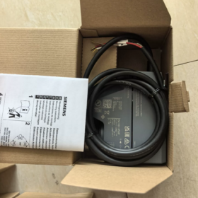
Descripción general del producto
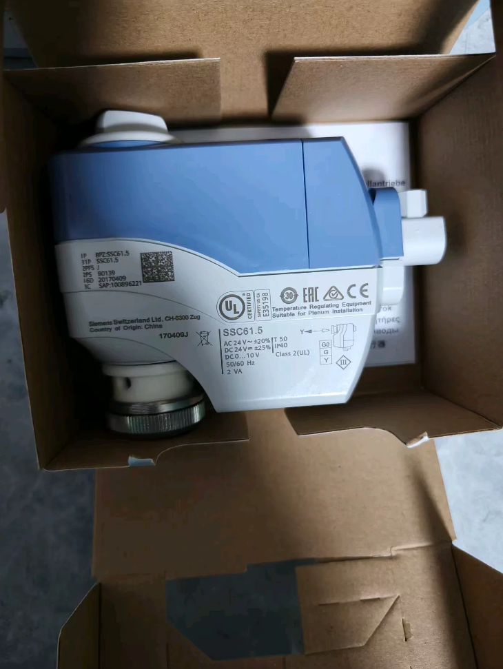
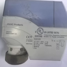
SSC61: 24 VCA/CC, 0~10 V DC modulating electric actuator, non-spring return (Fail-in-place; maintains current valve position upon power loss)
Designed for proportional flow control of chilled/hot water 2-way and 3-way valves on fan coil units, air handling units and terminal HVAC hydronic systems.
Comparison within the product series:
SSC61: 0–10 V modulating, non-spring return (no fail-safe reset)
SSC61.5: 0–10 V modulating, built-in supercapacitor, auto close-to-zero (valve shutoff) on power failure
SSC81: 24 V floating (3-posición) control
SSC31: 230 V floating (3-posición) control
- Especificaciones técnicas clave
| Artículo | Parámetro |
| Fuente de alimentación | AC/DC 24 V ±20%, 50/60 Hz |
| Consumo de energía | 2 Virginia |
| Señal de control | DC 0…10 V modulating signal; Input impedance>100 kΩ |
| Rated Thrust | 300 norte |
| Nominal Stroke | 5.5 milímetros |
| Full Stroke Run Time | 30 s (50 Hz) |
| Positioning Accuracy | <2% of stroke |
| Protección de ingreso | IP40 |
| Temperatura ambiente de funcionamiento | +5 ℃ ~ +50 ℃ |
| Permitted Water Medium Temperature for Valves | 1 ℃ ~ 110 ℃ (chilled / agua caliente, compatible with antifreeze) |
| Método de montaje | Direct coupling union nut, no tools required |
| Integrated Functions | Manual override knob, visual valve position indicator, automatic stroke calibration upon power-up |
| Maximum Parallel Quantity | Arriba a 10 actuators driven by one 24 V transformer |
| Peso | Aprox.. 0.26 kilos |
- Compatible Valves
- Direct mount (no se requiere adaptador)
VVP45… / VXP45… / VMP45… (Siemens threaded 2-way & 3-way control valves)
- Requires adapter kit ASK30
VVG45…, VXG45…, legacy Landis & Gyr X3i series valves
- Definición de terminal & Alambrado
Terminales: GRAMO, G0, Y
GRAMO / G0: AC/DC 24 V fuente de alimentación
Y: DC 0~10 V modulating control signal (output from controller)
Lógica de control:
Y=0 V → Valve fully closed; Y=10 V → Valve fully open; intermediate voltages correspond to linear proportional modulation
⚠️ SSC61 has no built-in valve position feedback output. Select alternative models if position feedback is required.
- Critical Notes for Power-Up Stroke Calibration
- The actuator must be mounted onto the valve before initial power-up. Powering up without valve load will cause permanent jamming.
- Automatic full-stroke travel to detect upper/lower limits; calibration lasts approx. 60 s. Control signal becomes effective after calibration completes.
- Recalibration is mandatory after actuator disassembly, re-installation or valve replacement.
- Escenarios de aplicación típicos
Modulating 2-way valves for fan coil temperature control, 3-way mixing valves for AHU heating/cooling coils, hydraulic regulation on compact air conditioning units, supply water modulation for radiant heating/cooling systems.
- Model Selection Guidelines & Evitar trampas
- If automatic valve shutoff upon power loss is required: Do not select SSC61, use SSC61.5 instead.
- If only switch control is available without a 0–10 V controller: Select SSC81 (3-position floating control).
- Do not connect more than 10 actuators to a single transformer to avoid voltage drop and insufficient power supply.
- Only applicable for low-pressure hot/chilled water closed systems; not suitable for steam service.
- Solución de problemas comunes
- Actuator fails to operate
Verificar 24 V fuente de alimentación; confirm variable 0~10 V signal on terminal Y
Check if jammed by no-load energization: Turn manual override knob to zero position, cut power and restart for recalibration
- Unstable modulating response
Separate signal cables from power cables to reduce electromagnetic interference; control wiring length recommended ≤50 m
- Cannot reach full open / full closed position
Valve plug jamming mechanically; re-execute automatic power-up calibration
Engineering Application Case Collection for Siemens SSC61 (0–10 V Modulating Actuator)
Montaje estándar: SSC61 + VVP45 (2-válvula de paso) / VXP45 (3-válvula de paso); 5.5 mm de carrera, 300 N thrust, non-spring return (holds valve position on power loss); compatible with DDC or standalone room controllers with DC0–10 V output.
⚠️ Critical selection boundary: Use SSC61.5 if fail-safe shutoff is required on power loss. All cases below apply to installations without power-failure safety shutoff demand.
Caso 1: 4-Pipe Fan Coil Modulating Temperature Control in Office Buildings (Más común)
Descripción general del proyecto
Multi-storey Grade A office with 4-pipe central air conditioning; high-precision zone temperature control for fan coil units, BMS DDC provides 0–10 V analog output.
Bill of Materials
Solenoide: SSC61
Valves: Chilled water circuit VVP45.20-4 (DN20 2-way); Hot water circuit VVP45.20-4
Controlador: Siemens DDC (PID output 0–10 V)
Lógica de control
Room temperature sensor collects indoor temperature → DDC PID calculation outputs 0–10 V signal:
0V = Valve fully closed; 10V = Valve fully open. Continuous modulation of chilled/hot water flow to stabilize room temperature within ±0.5 ℃.
Rationale for SSC61 Selection
- Stable power supply available in office buildings; low blackout risk, no requirement for power-failure reset.
- 30-second full stroke travel meets dynamic load variation of fan coils.
- Built-in automatic stroke calibration reduces commissioning workload for massive terminal units.
- Tamaño compacto, suitable for confined service space around fan coil units.
Commissioning Highlights
Complete mechanical installation before energization; prohibit no-load power-up.
Máximo 10 SSC61 units per 24 V transformer to avoid voltage drop.
Separate control wiring and power wiring to prevent interference on 0–10 V signal.
Caso 2: 3-Way Mixing Control for Heating & Cooling Coils on Compact AHU
Descripción general del proyecto
Fresh air handling unit (AHU) for shopping mall; 2-pipe hydronic system. 3-way mixing valve stabilizes supply air temperature by regulating mixed water temperature.
Bill of Materials
Solenoide: SSC61
Válvula: VXP45.25-6.3 (DN25 3-way mixing valve)
Lógica de control
Mixed chilled supply water and system return water via the 3-way valve. DDC adjusts valve opening according to supply air temperature to change mixing ratio and stabilize water temperature entering cooling coil.
VXP45 is recommended for mixing service only; diverting application is not advised.
Rationale for SSC61 Selection
AHU equipped with backup power; forced valve shutoff is unnecessary during short power interruption. Continuous proportional modulation delivers smaller supply air temperature fluctuation compared to on/off valves and reduces fan energy consumption.
Caso 3: Radiant Cooling & Floor Heating Branch Regulation for Hotel Properties
Descripción general del proyecto
Boutique hotel with ceiling radiant cooling + low-temperature hot water floor heating; independent hydraulic regulation for each guest room.
Bill of Materials
SSC61 + VVP45.15-2.5 DN15 2-way modulating valve
Process Description
Room thermostat outputs 0–10 V signal to continuously adjust water flow into radiant panels, preventing overcooling or overheating and eliminating temperature oscillation common with on/off valves.
Nota
Fully compatible with glycol antifreeze media (medium temperature range 1~110 ℃).
Caso 4: Reheat Coil Flow Control for Laboratory Constant-Temperature Air Handling Units
Descripción general del proyecto
Testing laboratory requiring precise indoor temperature & humidity stability. Fresh air is pre-cooled by chilled water, then reheated to fine-tune supply air temperature.
Configuración
SSC61 + VVP45.20 hot water 2-way control valve
Control Features
PID continuously modulates hot water flow to compensate fresh air load fluctuation. Uninterrupted power supply in the laboratory removes the need for fail-safe shutoff; SSC61 is adopted instead of SSC61.5 to save project cost.
Caso 5: Terminal Temperature Control Retrofit for Commercial Complex Heat Exchange Station
Retrofit Background
Original on/off electric valves caused large room temperature swings and frequent hydraulic shock to water pumps. Upgraded to modulating control.
Solución
Reuse existing threaded piping for direct replacement: SSC61 + VVP45 threaded valve, connected to BMS via 0–10 V analog output.
Retrofit Advantages
- Direct nut coupling without extra adapters.
- Manual override knob enables manual valve opening for draining during maintenance.
- Supports multi-actuator parallel control for unified regulation of large zones.
🔴 Universal Selection Red Rules Applicable to All Cases
- SSC61 MUST NOT be used for fire protection circuits, process safety loops or main chilled water valves in unattended mechanical rooms. Select SSC61.5 (capacitor-powered fail-safe shutoff) if valve shutoff is required upon power loss.
- V..P45 series valves have limited maximum shut-off differential pressure; do not deploy under high differential pressure conditions.
- Restricted to closed chilled/hot water circuits; steam service is prohibited.
- Do not install in locations with sustained ambient temperature exceeding 50 ℃.
📌 Quick Comparison Table: SSC61 VS SSC61.5
| Modelo | Características clave | Aplicaciones adecuadas | Aplicaciones no recomendadas |
| SSC61 | 0–10 V modulating, maintains valve position on power loss (no fail-safe reset) | Office FCU, habitaciones de hotel, continuously powered AHU, radiant heating/cooling | Fire safety circuits, process equipment, unattended mechanical rooms |
| SSC61.5 | 0–10 V modulating, auto shutoff upon power loss | Mechanical room coils, process air conditioning, circuits with freezing risk | Projects prioritizing budget without safety shutoff requirements |
Standard Installation & Commissioning Procedure for Siemens SSC61 Electric Actuator
Applicable to SSC61 (0~10 V modulating actuator, 5.5 mm de carrera, matched with VVP45/VXP45 series control valves)
⚠️ Critical Precondition: NEVER energize actuator without valve mounting. No-load power-up leads to permanent internal mechanical jamming.
- Inspección previa a la instalación
- Verificar modelo: SSC61, supply AC/DC24 V, control signal DC0~10 V
- Inspect valve: VVP45/VXP45 valve plug moves freely without sticking; clean valve stem, remove burrs and limescale
- Ambient confirmation: Operating temperature 5~50 ℃; keep away from steam, water dripping and intense radiant heat sources
- Required tools: Hand-tightening only for coupling nut (wrenches forbidden); flat screwdriver for wiring
- Pasos de instalación mecánica
- Adjust valve plug to mid-stroke position
Turn valve handwheel to extend valve stem to mid-position for smooth engagement with actuator.
- Rotate the black lock nut at the bottom of SSC61 fully downward.
- Align actuator vertically with valve stem and fit smoothly. Vertical upward mounting preferred; downward inverted installation is discouraged.
Horizontal side mounting is acceptable. Inverted downward mounting risks condensate ingress into actuator housing.
- Tighten bottom lock nut upward by hand only. DO NOT apply force with wrenches.
Over-tightening damages internal actuator seals and valve stem.
- Visual confirmation:
Actuator base fits flush against valve bonnet without tilt
Valve stem fully seated inside actuator plunger recess, no offset or binding
- Toggle side manual override knob, test full stroke travel manually; plunger extends and retracts smoothly without abnormal friction noise.
- Electrical Wiring (Terminales: GRAMO, G0, Y)
Definición de terminal:
GRAMO, G0: 24 V AC/DC power supply
Y: 0~10 V DC modulating control signal (output from DDC / termostato de ambiente)
Especificaciones de cableado:
- Perform wiring only when power is disconnected!
- Shielded cable recommended for control wiring; shield grounded at single end. Separate control cables and power cables with minimum spacing ≥15 cm.
- Do not route 230 V power cables together with 0~10 V signal cables in the same conduit.
- Parallel installation: máx.. 10 units per transformer to avoid voltage drop.
No built-in valve position feedback; no extra wiring required for feedback.
- Power-Up & Automatic Stroke Calibration (Most Critical Commissioning Step)
- Confirm mechanical assembly and wiring before applying 24 V power.
- Automatic calibration sequence starts after energization (duration approx. 45~60 segundos).
Movement sequence: Plunger travels to fully closed limit → fully open limit → returns to initial position.
- Do not feed control signal or operate manual override knob during calibration.
- Actuator enters standby mode after calibration; 0~10 V control signal becomes active.
Recalibration mandatory if:
Actuator disassembled and re-installed
Valve replaced
Valve maintenance performed
- Functional Test
- Controller output Y=0V: Plunger retracts, valve fully closed
- Controller output Y=5V: 50% mid-position
- Controller output Y=10V: Plunger extends, valve fully open
- Ramp control signal repeatedly; check smooth movement without jitter or abnormal noise.
- Prohibiciones de instalación (Hard Rules)
- ❌ Long-term inverted downward mounting of actuator is forbidden
- ❌ Do not use wrenches to tighten lock nut; hand tightening only
- ❌ No power supply without valve mounted (risk of permanent jamming)
- ❌ Media temperature exceeding 110 ℃ is not permitted
- ❌ Cannot be fitted onto steam valves directly
- ❌ Power cut during calibration causes misrecognized limit positions; cut power, esperar 3 minutes and restart calibration.
- Disassembly Procedure for Maintenance
- Disconnect 24 V fuente de alimentación
- Toggle manual override knob to retract plunger to fully closed position
- Unscrew bottom lock nut downward by hand
- Lift actuator vertically upward to remove
Recalibration on power-up is required after re-installation.





NH42-63-318x560.png "Interruptores de transferencia automática tipo PC CHINT (ATS)NH42-63/4SZ")



