 Contacteur,disjoncteur,capteur,Encodeur,API,Convertisseur

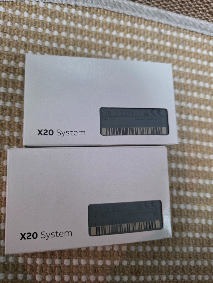

Explication du code modèle
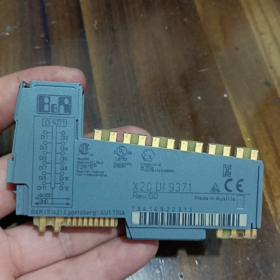
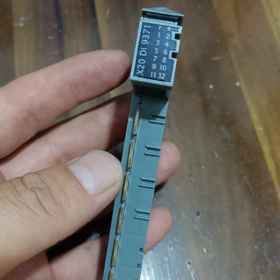
X20DI9371
X20: X20 distributed I/O system platform
DEPUIS: Entrée numérique
9371: Module specification code
- Main Electrical & Hardware Specifications
| Article | Spécification |
| Nombre de canaux | 16 entrées numériques |
| Type d'entrée | 24 VDC sinking / sourcing compatible, CEI 61131-2 Taper 3 |
| Tension d'entrée nominale | 24 VCC (plage de fonctionnement: 18~30 VCC) |
| Impédance d'entrée | Environ. 3.9 kΩ |
| Logic ON (1) Threshold | ≥11 VDC |
| Logic OFF (0) Threshold | ≤5 VDC |
| Input Current per Channel | ≈6 mA @24 VDC |
| Délai de réponse | Typique 0.1 MS; configurable hardware filter: 0.1 / 0.5 / 3 / 15 MS (parameter setting via software) |
| Méthode d'isolement | Group isolation: 4 chaînes par groupe, total 4 groupes isolés |
| Isolation voltage between groups: 500 ACC | |
| Interface de bus | X20 Link internal system bus |
| Indication d'état | Independent LED for each channel; module power LED |
| Consommation d'énergie | Typ. 1.8 W |
- Mécanique & Spécifications environnementales
Montage: Standard 35 mm rail DIN, installation horizontale
Dimensions: W 40 mm × H 100 mm × D 76.5 mm
Température de fonctionnement: -20 ℃ ~ +60 ℃ (à l'intérieur de l'armoire de commande)
Stockage / Température de transport: -40 ℃ ~ +85 ℃
Classe de protection: IP20 (pour installation en armoire uniquement)
Certifications: CE, UL 508, Certification maritime GL, conforme à la norme EN 61000 EMC industrial standards
- Structure interne & Définition du terminal
16 chaînes divisées en 4 groupes isolés:
Group1: CH0~CH3
Group2: CH4~CH7
Group3: CH8~CH11
Group4: CH12~CH15
⚠️ Important Wiring Rule: The common terminal of one isolated group must share the same 24 V polarity; Do NOT connect separate, non-referenced 24 V power supplies to different isolated groups, otherwise potential difference may damage the isolation circuit.
Wiring Configurations
- Sourcing Input (PNP Capteur)
Sensor output connects to module DI terminal; module common terminals connect to 0V(GND)
- Sinking Input (Capteur NPN)
Sensor power terminal connects to 24V+, sensor output to DI terminal; module common terminals connect to +24V
- Principe de fonctionnement
External digital sensor signal → Front-end RC hardware filter circuit → Optocoupler isolation group → Signal shaping circuit → X20 bus communication chip
The controller cyclically reads channel status via X2X/X20 CPU. Filter time parameters can be configured in Automation Studio to suppress contact bounce and interference pulses generated by inverters.
- Informations sur le logiciel
Logiciel de programmation: Studio d'automatisation 4.0 and all later versions supported
Hardware Identification: Standard X20 device description built-in library, no extra GSD file required
Image de processus: Automatic channel address mapping; support signal forcing & online signal monitoring
Fonctions prises en charge: Channel diagnosis (no wire break detection, X20DI9371 does not support wire break diagnosis)
- Comparaison des modèles & Remplacement compatible
Comparison with similar models in X20 series
| Modèle | Canaux | Fonction d'isolation | Caractéristiques |
| X20DI9371 | 16DEPUIS | 4 channels per isolated group | Standard general-purpose module, largement utilisé dans les projets |
| X20DI9372 | 16DEPUIS | Full channel individual galvanic isolation | Pour les environnements à fortes interférences, multi-signals with different potentials |
| X20DI4371 | 4DEPUIS | 4 channels per isolated group | Compact module for limited I/O points |
✅ Direct Replacement Conditions
If X20DI9371 is used in existing projects:
Upgrade for higher anti-interference performance: X20DI9372 (pin assignment compatible, aucune modification du programme requise, wiring fully interchangeable; only difference is enhanced isolation performance)
❌ Not directly interchangeable: X20DI4371 has different channel quantity and terminal layout of base unit
- Scénarios d'application typiques
Machines-outils, machines d'emballage, convoyeurs de manutention, caoutchouc & plastic equipment, traitement de l'eau, general automation production lines
Acquisition de signaux: Détecteurs de proximité, capteurs photoélectriques, interrupteurs de fin de course, boutons-poussoirs, passive relay contacts
- Directives d'installation & Dépannage
Strict Prohibitions
- Never apply voltage higher than 30 VCC, will permanently damage input circuits
- Do not connect two non-common-ground 24 V power supplies to different isolated groups
- Avoid parallel routing of signal cables and power cables (strong electrical interference leads to flickering signals)
Défauts courants
- Channel LED always ON: Signal wire short-circuited to ground; abnormal power supply for PNP sensor
- Signal intermittent fluctuation: Severe electromagnetic interference → increase hardware filter time; check shielding & mise à la terre
- All channels in one group no signal: Loss of power supply to the corresponding group common terminal
- Unités de base compatibles
Socle standard: X20BM01 (screw terminal base)
Optional base: X20BM11 (spring-cage quick connect terminal)
Base must be ordered separately; terminal base is NOT included with the module!
X20DI9371 Terminal Pin Assignment
Socle compatible: X20BM01 (vis) / X20BM11 (borne à ressort)
16 channels split into 4 galvanically isolated groups (4 channels each)
Group1: CH0~CH3|Group2: CH4~CH7|Group3: CH8~CH11|Group4: CH12~CH15
Terminal Sequence (Top to bottom on base)
Groupe 1 (CH0~CH3)
1: DI0
2: DI1
3: DI2
4: DI3
5: COM0 (Common terminal for Group1)
Groupe 2 (CH4~CH7)
6: DI4
7: DI5
8: DI6
9: DI7
10: COM1 (Common terminal for Group2)
Groupe 3 (CH8~CH11)
11: DI8
12: DI9
13: DI10
14: DI11
15: COM2 (Common terminal for Group3)
Groupe 4 (CH12~CH15)
16: DI12
17: DI13
18: DI14
19: DI15
20: COM3 (Common terminal for Group4)
Wiring Specifications Recap
- Capteur PNP (Sourcing Input, Industry Standard)
All COM0/COM1/COM2/COM3 → connect to 24 VCC 0 V(GND)
Sensor signal wire to DIx, sensor positive terminal to 24V+
- Capteur NPN (Sinking Input)
All COM0/COM1/COM2/COM3 → connect to +24 VCC
Sensor signal wire to DIx, sensor negative terminal to 0V
⚠️Important: COM0/COM1/COM2/COM3 are galvanically isolated from each other.
Do not connect different COM terminals to power supplies with non-shared ground potential!
Steps to Configure Input Filter in Automation Studio
- Locate X20DI9371 in project tree and double-click to open configuration window
- Nom du paramètre: Input filter time
Selectable options:
0.1 MS (réponse rapide, pour signaux à grande vitesse)
0.5 MS
3 MS (recommended for normal pushbuttons & détecteurs de proximité)
15 MS (heavy interference environment, suppress contact bounce)
- Download project; parameters take effect immediately without power cycle



NH42-63-318x560.png "Commutateurs de transfert automatiques de type PC CHINT (ATS)NH42-63/4SZ")



