 Contacteur,disjoncteur,onduleur solaire,compteur électrique,batteries solaires

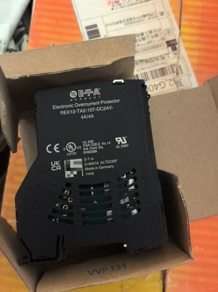

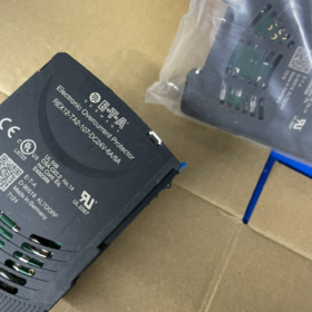
ETA REX12-TA2-107 Modular Current Protection Disjoncteur
- Répartition du code modèle
Model split: REX12 TA2 107
- REX12: ETA REX12 series modular current protection circuit breaker (electronic overload protector / miniature electronic circuit protector, DIN rail mounted)
- TA2: Sub-series functional code, 2-channel universal type for DC and AC, equipped with temperature monitoring and fault signal output
- 107: Rated current specification code → Rated current 7A
- Brand Overview
ETA (Swiss ETA): A global brand of industrial electronic protection components, specializing in miniature equipment circuit breakers, electronic overcurrent protectors and thermal-magnetic circuit breakers. Widely applied in industrial control cabinets, robotique, transport ferroviaire, photovoltaic energy storage and medical devices.
REX12 Series: Ultra-thin modular electronic protection devices as a replacement for traditional fuses, featuring remote signal feedback and precise segmented current limiting.
III. Spécifications de base (REX12-TA2-107)
Spécifications électriques
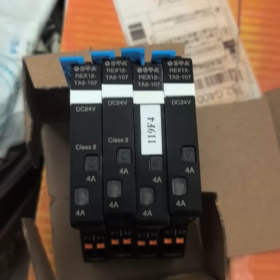
Rated Current In: 7UN
Canaux: Dual independent protection channels (separate current limiting and fault alarm for two outputs)
Tension de fonctionnement: Universal for DC 24V / AC 24~230V
Type de voyage: Electronic inverse-time overload protection + instantaneous short-circuit cut-off
Signal Output: TA2 standardly equipped with two sets of passive fault contacts (NON/NF, connectable to PLC for fault signal collection)
Montage: Rail DIN standard de 35 mm, module width only 12mm per channel
Caractéristiques fonctionnelles
- Independent circuit protection for dual channels without mutual interference
- Precise electronic current limiting, eliminating aging issues of traditional fuses
- Manual reset after overload/short-circuit tripping; no consumable replacement required
- Remote fault alarm contacts for automated equipment monitoring
- Faible consommation d'énergie, ultra-thin design dedicated to dense cabinet wiring
- Scénarios d'application typiques
24V DC output circuit protection for industrial PLCs and servo drives
Branch power supply protection for robot IO modules and sensors
Multi-channel DC power supply protection for medical equipment and test instruments
On-board control cabinets for rail transit and auxiliary circuits of energy storage BMS
- Reference Alternative Models within the Same Series
REX12-TA2-103: 3A dual-channel
REX12-TA2-105: 5A dual-channel
REX12-TA2-110: 10A dual-channel
REX12-TA1-XXX: Basic single-channel model (without separate dual-channel alarm)
- Key Distinction Points
TA1 = single channel; TA2 = dual channel with independent fault signals; the last two digits of the three-digit suffix represent rated current (107 = 7A).
Full Technical Analysis of ETA REX12-TA2-107 Electronic Overcurrent Protector
> Note: The previous interpretation of the model suffix “107” was inaccurate.
- Digit-by-Digit Model Code Decoding
Standard full ordering format: `REX12 TA2 107 DC24V XA/XA`
The provided `REX12-TA2-107` is the abbreviated base model of the series; full purchasing models require supplementary suffix current specifications.
| Segment de code | Définition |
| REX12 | Main product series: 12.5mm ultra-thin modular electronic DC circuit breaker with standard Push-in spring terminals |
| T | Type de montage: Clip-on for standard 35mm DIN rail |
| UN | Type de structure: One set of load output terminals per channel with fixed rated current specifications |
| 2 | Channel quantity: Dual independent protection channels with fully separate current limiting and status feedback |
| 107 | Function version code: Standard dual-channel independent fault status signal output; basic version without bus communication |
| DC24V | Tension de fonctionnement nominale: 24V DC system, compatible with wide voltage range of 18~30V DC |
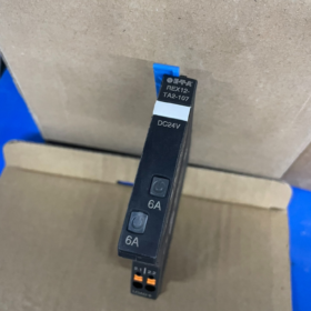
| XA/XA | Rated current specification: Symmetrical dual-channel setting, optional 1A/1A, 2A/2A, 3A/3A, 4A/4A, 6A/6A |
- Full List of Core Specifications
Spécifications électriques
| Paramètre | Valeur |
| Tension de fonctionnement nominale | C.C 24 V (operating range: 18~30V DC) |
| Number of Channels | 2 electrically independent channels |
| Optional Rated Currents | 1UN, 2UN, 3UN, 4UN, 6UN (symmetrical dual-channel configuration) |
| Caractéristiques de déclenchement | Electronic inverse-time overload protection + instantaneous short-circuit cut-off |
| Capacité de coupure de court-circuit | Max.. 40Un DC |
| Capacitive Load Tolerance | Supports startup of capacitive loads up to 20000渭F without false tripping |
| Status Signal Output | Independent open-collector fault signal per channel, directly connectable to PLC DI modules |
| Indication d'état | Independent LED per channel: Green = Normal Operation, Orange = Overload/Short-Circuit Fault |
| Méthode de réinitialisation | Réinitialisation manuelle par bouton-poussoir; one-click power recovery after fault elimination |
| Protection des sauvegardes | Built-in blade fuse matching the rated current as a safety barrier against electronic component failure |
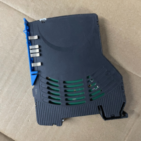
Mécanique & Mounting Specifications
| Paramètre | Valeur |
| Module Width | 12.5 mm (single module integrating two channels) |
| Dimensions hors tout (L × H × P) | 12.5 × 80 × 98.5 mm |
| Méthode de câblage | Tool-free Push-in spring terminals |
| Applicable Wire Cross-Section | 0.5 ~ 2.5 mm² (flexible / solid conductors) |
| Single Module Weight | Environ. 40 g |
| Power Distribution Expansion Capacity | Jusqu'à 16 protection modules can be connected in parallel to one power supply set when paired with EM12-T power distribution modules |
III. Mécanisme de protection & Principe de fonctionnement
- Precision Electronic Sampling: Built-in current sensors collect real-time circuit current; a dedicated chip executes inverse-time tripping algorithms. Higher overload multiples lead to faster tripping, precisely matching cable thermal withstand capacity with far lower dispersion than traditional fuses.
- Microsecond-Level Short-Circuit Cutoff: Upon detection of short-circuit current, semiconductor switches shut down within microseconds to limit fault current rise, preventing surge damage to downstream loads and avoiding tripping of the upstream switching power supply.
- Fail-Safe Backup Protection: Built-in blade fuses compliant with IEC 60127-4 and UL248-14 standards. When electronic protection components malfunction, the fuse acts as the final safety barrier, conforme à la norme EN 60204-1 for machine equipment cable protection.
- Selective Disconnection: Only the faulty branch is cut off while other branches remain powered, greatly improving system availability and avoiding full power supply shutdown caused by single-point faults.
- Installation Wiring & System Configuration
Power Distribution Connection
Power input is uniformly connected via EM12-T power distribution modules. Side bridging arms enable parallel power supply between modules without additional jumper wires. A single set of distribution modules supports up to 16 parallel protection modules; matched PM12-T potential expansion modules enable separate GND circuit routing.
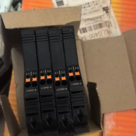
Charger & Signal Wiring
Load Side: One set of Push-in terminals per channel for direct connection to load positive circuits; longueur de dénudage des fils: 8~10mm.
Signal Side: Independent fault signal output terminals per channel, connectable to PLC DI modules for remote fault monitoring and alarm.
Précautions d'installation
Mount modules vertically on DIN rails with at least 10mm clearance above for heat dissipation.
AC voltage input is strictly prohibited; the device is only applicable to 24V DC systems.
- Certifications de sécurité & Normes de conformité
UL 508 Certification for Industrial Control Equipment
UL 2367 Solid-State Circuit Breaker Certification
cULus Dual Certification for Canada & les États-Unis
DANS 60204-1 Electrical Equipment Standard for Machinery (cable protection compliance)
CEI 60127-4 Miniature Fuse Standard (backup fuses)
RoHS Environmental Compliance
- Model Selection Comparison within the Same Series
| Modèle | Channel Quantity | Différences fondamentales | Plage de courant nominal |
| REX12-TA1-107 | Single Channel | Single-circuit protection, single signal output | 1A~10A |
| REX12-TA2-107 | Dual Channel | Independent dual-circuit protection, dual signal outputs | 1A~6A (symmetrical) |
| REX12-TB2-107 | Dual Channel | Two sets of load terminals per channel for parallel connection of two loads | 1A~6A (symmetrical) |
| REX12D-TA2 | Dual Channel | Intelligent type supporting Profinet/EtherCAT communication with adjustable current | Adjustable 1A~10A |
VII. Scénarios d'application typiques
Branch protection for 24V DC power distribution systems in industrial control cabinets
Power supply protection for field components including PLC IO modules, capteurs, solenoid valves and indicator lamps
Lignes de production automatisées, robot control cabinets and semiconductor manufacturing equipment
Auxiliary circuits of new energy storage BMS and on-board control cabinets for rail transit
Multi-channel low-voltage power supply protection for medical testing equipment and laboratory instruments
VIII. Matrice de dépannage des pannes courantes
| Phénomène de défaut | Analyse des causes profondes | Solutions étape par étape |
| Orange LED stays on after power-on with no output | Unresolved short circuit or continuous overload on load side | 1. Disconnect all loads; 2. Press reset button to verify module recovery; 3. Reconnect loads one by one to locate short-circuit point |
| Frequent tripping under loaded startup | Excessively large capacitive load or excessive startup current peak | 1. Confirm load startup current peak value; 2. Replace with higher current specification; 3. Check for hidden short circuits |
| No voltage output after reset | Internal backup fuse blown (triggered after electronic protection failure) | Replace the entire protection module with identical specifications; do not short-circuit the fuse or disassemble for self-repair |
| No fault signal output | Reversed polarity of signal wiring or incorrect PLC DI configuration | 1. Verify positive/negative polarity definition of signal terminals; 2. Check common terminal polarity and parameter settings of DI modules |
- Terminal Pinout & Wiring Definition
The REX12-TA2-107 adopts a system-level bridging architecture. Power input is connected in parallel via side-mounted matching EM12-T power distribution modules, while load and signal terminals are wired directly on the front face. Terminals are divided into three major functional zones:
- Terminal Zones & Pin Definitions
From top to bottom on the module front (operation side), terminals are divided into power bridging zone, load output zone and signal output zone. Detailed pin definitions are as follows:
| Zone | Marquage des bornes | Description de la fonction | Spécification de câblage |
| Top Power Bridging Zone | Internal bridging contacts | Automatically parallel DC24V positive power supply when installed side-by-side with EM12-T distribution modules; no external wiring required | Uniformly powered by distribution modules, maximum. 40A per circuit |
| Middle Load Output Zone | LOAD+ CH1 | Canal 1 load positive output (positive switching type; positive circuit cut off upon overcurrent) | 0.5~2.5 mm簡 solid/flexible wires, stripping length 8~10mm |
| Middle Load Output Zone | LOAD+ CH2 | Canal 2 load positive output, fully electrically isolated from Channel 1 | Idem que ci-dessus |
| Lower Signal Output Zone | Si CH1 | Canal 1 fault signal output (open-collector, negative switching; conducts to negative pole during faults) | 0.5~1.5 mm簡 signal wires, connected to PLC DI modules |
| Lower Signal Output Zone | Si CH2 | Canal 2 independent trigger fault signal output | Idem que ci-dessus |
| Common Negative Circuit | GND | Load negative and common signal negative require external connection to power supply negative; unified distribution via PM12-T potential expansion modules | Equipotential with power supply negative |
> Core Note: This model is a positive-side protection type, which only cuts off the load positive circuit while the negative circuit remains continuously connected. Fault signals are low-level active (NPN type), directly compatible with DI input modules of mainstream PLC brands including Siemens and Mitsubishi.
- Spécifications de câblage & Précautions
All terminals are Push-in spring terminals; wires can be inserted or removed by pressing the orange release button without tools.
The module must be installed side-by-side with EM12-T series power distribution modules to receive operating power; standalone modules cannot be powered on.
A single EM12-T distribution module supports up to 16 parallel REX12 protection modules with total current not exceeding 40A.
No additional current limiting required for capacitive load startup; each channel supports shock-free startup of capacitors up to 20000μF.
Charges inductives (électrovannes, relais) require freewheeling diodes connected in parallel on the load side to prevent reverse voltage breakdown of internal MOSFETs.
- Cross-Brand Compatible Replacement Solutions
The ETA REX12 series adopts a proprietary bridging power distribution architecture, with no cross-brand models offering 1:1 fully compatible pinouts. Two replacement categories sorted by ascending replacement cost are listed below:
Solution 1: Same Footprint Functional Replacement (Retain DIN Rail Space, Replace Distribution & Protection Modules)
Suitable for cabinets with limited space where the 12.5mm dual-channel width must be maintained; power distribution modules also require simultaneous replacement.
| Marque | Replacement Model Combination | Spécifications de base | Description de la différence |
| Contact Phénix | 2 pcs PTCB E1 single-channel (par exemple. 2800905 6UN) + base module | Single channel width 6.2mm, total width 12.4mm for two pieces; 24VCC; with fault signal output; Push-in wiring | Nearly identical width; two single-channel units combined to realize dual channels; independent wiring power supply without bridging architecture |
| WAGO | Combiné 787-2861 series single-channel units | Single channel width 6mm, total width 12mm for two pieces; 24VCC; independent signal contacts; spring wiring | Spring wiring terminals, current specifications cover 1~10A; requires separate power supply wiring |
Solution 2: Independent Dual-Channel Functional Replacement (Direct Complete Unit Replacement, No Matching Distribution Modules Required)
Suitable for scenarios where the original REX12 power distribution system is not retained and independent wiring is adopted; higher integration and more flexible wiring.
| Marque | Modèle de remplacement | Spécifications de base | Compatibilité |
| WAGO | 787-1662/000-060 | Independent dual-channel protection; 24VCC; adjustable current 2~10A; common group alarm contacts; width 22.5mm | Full function coverage with adjustable current and remote reset; légèrement plus large, suitable for cabinets with ample space |
| Weidmüller | ESM 24VDC 2CH 6A | Fixed current dual channels; 24VCC; fault signal output; DIN rail mounted; Push-in wiring | Industrial-grade electronic circuit breaker with nearly identical protection characteristics and consistent wiring method |
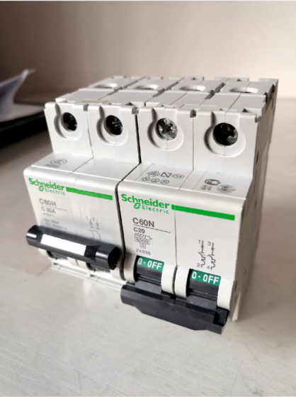
| Schneider Électrique | Dual-channel ABL2REM24020 | 24VCC; independent dual-channel protection; status indicators; width 18mm | Matching model for Schneider power distribution systems, ideal for full-Schneider cabinet solutions |
Key Replacement Reminders
- Power Distribution Architecture Difference: The side bridging power supply of REX12 is an ETA patented design; all other brands adopt independent terminal wiring, requiring re-routing of power input lines during replacement.
- Signal Type Matching: REX12 outputs NPN open-collector signals; confirm the signal output type (NPN/PNP/passive contact) of replacement models to match the existing PLC system.
- Caractéristiques de déclenchement: All alternative models feature electronic inverse-time overload protection and instantaneous short-circuit cutoff, with protection curves basically consistent with REX12 for direct replacement.


 de la série Schneider TeSys GV2. Il dispose d'un réglage de courant réglable de 24 à 32 A.,")


")
NH42-63-318x560.png "Commutateurs de transfert automatiques de type PC CHINT (ATS)NH42-63/4SZ")


