 Contacteur,disjoncteur,onduleur solaire,compteur électrique,batteries solaires


1. Présentation du produit
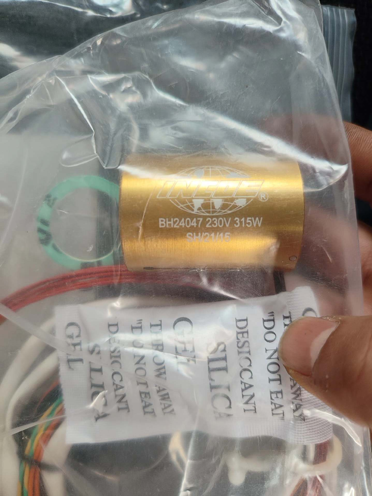
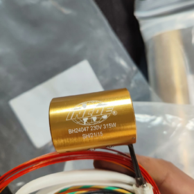
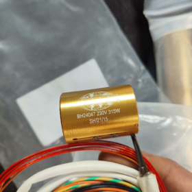
The INCOE BH24047-230V-315W is a spring-style nozzle heater coil with integrated thermocouple, specially designed for hot runner systems of injection molds. It is an original heating component matched with standard INCOE nozzles.
Constructed with nichrome heating wire, high-temperature resistant stainless steel sheath and magnesium oxide insulation filler, it delivers 360° uniform circumferential heating to maintain stable nozzle temperature and eliminate cold spots. It is applicable to injection molding of general-purpose and engineering plastics such as PP, ABS, PC, PA66 and PPS.
Equipped with a built-in Type J thermocouple, it realizes closed-loop precise temperature control when paired with a hot runner temperature controller. Powered directly by the temperature controller and mounted on the outer wall of hot runner nozzles, it serves as a core heating part for hot runner systems of injection molds used for automotive interior & exterior parts, precision connectors, packaging products and more.
2. Spécifications techniques
| Catégorie | Article | Description |
| Informations de base | Modèle | BH24047-230V-315W (INCOE Nozzle Heater Coil) |
| Marque / Original Part No. | INCOE, BH24047 | |
| Compatible Object | Standard INCOE hot runner nozzles (straight nozzle / pointed nozzle) | |
| Paramètres électriques | Tension nominale | 230V et (Monophasé) |
| Puissance nominale | 315W | |
| Rated Resistance | Environ. 167.9Oh (230²÷315) | |
| Courant nominal | Environ. 1.37UN (315÷230) | |
| Thermocouple Type | Built-in standard Type J (Fe-CuNi) thermocouple | |
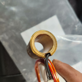
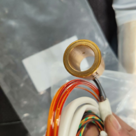
| Structure & Matériel | Structure | Spring coil type (flexible to fit closely to nozzle outer wall) |
| Sheath Material | High-temperature resistant SUS304/316 stainless steel / Inconel alloy | |
| Insulation Filler | High-density Magnesium Oxide (MgO), dielectric strength ≥ 2kV | |
| Taille du fil & Dimension | Standard spring cross-section, fits nozzle outer diameter φ16~φ20mm (typique) | |
| Temperature Performance | Maximum Sheath Temperature | ≤ 650℃ |
| Long-term Operating Temperature | 400~550℃ (for conventional engineering plastics) | |
| Physique & Installation | Configuration du câblage | 2 heating wires + 2 thermocouple wires (4-core connector) |
| Méthode de montage | Tightly fitted on nozzle outer wall, fixed with clips or high-temperature adhesive | |
| Protection contre la pénétration | IP40 (installed inside mold) | |
| Attestation | Approvals | CE, RoHS, UL (Compliant with hot runner industry standards) |
3. Cross-brand Equivalents
Interchangeable hot runner nozzle heater coils with identical specifications and performance in the market:
| Marque | Modèle équivalent | Spécification nominale | Fonctions principales |
| Hotset (Allemagne) | HS-24047 | 230V/315W, Type J thermocouple | Spring coil, uniform heating, fits standard nozzles |
| Hotspring | HSC-24047 | 230V/315W, Type J thermocouple | Flexible coil, fast heat-up, withstands up to 550℃ |
| Hotslot | HSN-24047 | 230V/315W, Type J thermocouple | Dedicated for standard nozzles, high-temperature insulation |
| Alternative nationale (Hongtai / Leier) | HT-BH24047 | 230V/315W, Type J thermocouple | Fully compatible in dimension and interface, rentable |
4. Full Product List of the Series
INCOE BH Series Hot Runner Nozzle Heater Coils (Classified by Power & Tension):
1. BH24047-230V-315W: Version standard, fits φ18mm nozzles for general injection molding applications (Subject model)
2. BH24048-230V-400W: High-power version, for large-diameter / long nozzles and high-melting-point engineering plastics (PPS/PEI)
3. BH24046-230V-250W: Low-power version, for small-diameter / short nozzles and thin-wall small products
4. BH24047-240V-315W: North American voltage version, compatible with 240V power systems
5. BH24047-230V-315W-K: Custom version with Type K thermocouple, matching temperature controllers of certain brands
5. Environnement opérationnel & Dépannage
5.1 Applicable Environment
Installed inside the cavity of injection mold hot runners and on the outer wall of nozzles. Mold temperature: 80~120℃, no direct water immersion.
Standard injection workshop: Ambient temperature 10~45℃, humidité relative ≤85%, no strong acid/alkali corrosion and excessive dust accumulation.
Suitable for molding of general plastics such as PP, ABS, PC, PA66, POM and medium-temperature engineering plastics.
Adopt closed-loop temperature control with INCOE TTC / Microcom series hot runner temperature controllers.
5.2 Restricted Environment
Long-term over-temperature operation: Continuous working above 550℃ will burn out insulation and shorten service life.
Severe corrosion, high humidity or water immersion: Areas with acid/alkali vapor, condensation water and cooling water leakage may cause electric leakage and short circuit.
Severe vibration and impact: Frequent high-speed mold opening & closing and impact vibration may lead to coil breakage and loose wiring.
Direct contact with melt or gate: For nozzle outer wall heating only; never embed the coil into the melt flow channel.
5.3 Défauts courants & Solutions
| Phénomène de défaut | Cause première | Solutions |
| Temperature controller alarm / No heating / Résistance infinie | Broken heating wire, long-term over-temperature / surcharge, aging insulation, câblage lâche | 1. Cut off power and measure resistance (Normal value: environ. 168Oh); 2. Replace with heater coil of the same specification; 3. Check controller output and avoid over-temperature |
| Court-circuit / Electric leakage / Residual current circuit breaker tripping | Rupture d'isolation, eau / melt ingress, damaged sheath, damp magnesium oxide filler | 1. Cut off power and test insulation resistance with megohmmeter (Qualifié: ≥1 MΩ); 2. Clean residual melt and dry the cavity; 3. Replace heater coil and implement effective sealing & waterproofing |
| Out-of-control temperature / Severe temperature drift | Broken / reversed thermocouple wire, mauvais contact, aged thermocouple | 1. Check thermocouple polarity and re-tighten connection; 2. Measure millivolt value of thermocouple; 3. Replace with Type J thermocouple |
| Local overheating / Red-hot coil / Uneven temperature | Poor fitting between coil and nozzle, excessive gap, local carbon deposition | 1. Remove carbon deposits and oxide layers on nozzle surface; 2. Reinstall and fix the coil tightly; 3. Check power output of temperature controller |
| Slow heat-up / Failure to reach set temperature | Power attenuation, partial turn-to-turn short circuit, low supply voltage, excessive heat dissipation | 1. Measure actual resistance and current; 2. Check supply voltage; 3. Install new heater coil and optimize thermal insulation structure |
Supplementary Guidelines for INCOE Hot Runner Systems
Below is a complete guide covering applicable environment, restricted environment, critical operating limits, diagnostic de panne & solutions and preventive maintenance, complying with original factory requirements and on-site operation standards for INCOE hot runners (including BH24047 series heater coils).
1. Applicable Environment
INCOE hot runners are installed inside injection molds, requiring stable temperature control, reliable heat insulation, low electromagnetic interference and no direct water exposure.
1. Workshop Environment: Ambient temperature 10~45℃, humidité relative ≤85%. Free from condensation, corrosive vapor and heavy dust. Keep away from strong electromagnetic interference sources such as high-frequency welders and high-power motors.
2. Mold & Circuit de refroidissement: Mold temperature 80~120℃. Never let cooling water jets blow directly onto hot runner areas. Maintain a thermal clearance of no less than 15mm between cooling water channels and hot runners/nozzles. Ensure heat insulation gaskets and plates are intact with an air insulation layer ≥10mm to reduce heat loss.
3. Processus & Raw Materials: Compatible with general and medium-to-high temperature engineering plastics including PP, ABS, PC, PA66, POM and PPS. Raw materials shall be fully dried, free of metal impurities, and the proportion of regrind materials shall comply with regulations. Normal melt temperature ranges from 200℃ to 450℃, with a maximum limit of 550℃.
4. Électrique & Exigences d'installation: Stable power supply (230V AC ±5%). Standard Type J (Fe-CuNi) thermocouple shall be used and matched with the temperature controller. Junction boxes shall be well sealed and cables protected from extrusion and sharp bending. Ensure flat installation, good concentricity and reserved gaps for thermal expansion.
2. Restricted Environment (Critical Rules)
1. Extreme Temperature, Humidité & Water Ingress: Long-term operation below 5℃ or above 50℃ is prohibited. Water leakage inside molds or condensation penetrating into hot runner cavities and wiring areas will easily cause insulation breakdown, electric leakage and short circuit.
2. Severe Corrosion, Poussière & Vibration: Avoid exposure to acid, alkali and sulfide vapor, heavy dust and metal debris. Intense impact and vibration caused by high-speed mold movement may result in coil fracture, thermocouple detachment, seal failure and melt leakage.
3. Surchauffe & Surcharge: Continuous operation above 550℃ and long-term overload will damage heater insulation, accelerate carbonization and shorten service life drastically.
4. Improper Electrical Configuration: Mismatched Type K thermocouple, reversed polarity, inconsistent supply voltage, loose wiring and poor shielding & grounding will lead to temperature drift, signal interference and circuit tripping.
5. Non-compliant Assembly & Structure: Missing heat insulation or insufficient gaps, damaged sealing surfaces of nozzles/manifolds, improper fastening torque and inadequate thermal expansion allowance will directly cause melt leakage and component jamming.
3. Défauts courants, Causes & Solutions
3.1 Abnormal Temperature Control (Le plus courant, including BH24047 Heater Coil)
(1) No heating / Slow heat-up / Abnormal resistance
Phénomène: Set temperature fails to rise or rises extremely slowly; controller reports open circuit or broken thermocouple; measured resistance deviates from nominal value (environ. 168Oh) or shows infinite resistance.
Causes: Broken heating wire, partial turn-to-turn short circuit, loose or detached wiring, faulty output of temperature controller, broken or poorly contacted thermocouple, excessive heat loss (mauvaise isolation, cooling channels too close).
Solutions:
1. Cut off power, measure resistance of heater coil and millivolt value of thermocouple with a multimeter.
2. Fasten terminals and inspect connectors.
3. Replace with qualified Type J thermocouple or BH24047-230V-315W heater coil.
4. Check heat insulation and adjust layout of cooling channels.
5. Test output modules of the temperature controller by cross replacement.
(2) Temperature drift / Large fluctuation / Over-temperature alarm
Phénomène: Deviation between actual and set temperature exceeds ±5℃ with sudden jumps; over-temperature occurs without heating command.
Causes: Reversed polarity or mismatched Type K thermocouple, loose/damaged/aged thermocouple, drifted controller parameters, mismatched PID parameters, electromagnetic interference and poor grounding, partial short circuit of heater coil and uneven power output.
Solutions:
1. Verify thermocouple type (INCOE standard: Type J) and polarity, then reattach firmly.
2. Calibrate temperature controller and optimize PID parameters.
3. Implement cable shielding and reliable grounding; keep cables away from power lines.
4. Replace faulty heating or temperature sensing components.
(3) Electric leakage / Circuit tripping
Phénomène: Residual current circuit breaker trips, insulation alarm triggered, measured insulation resistance below 1MΩ via megohmmeter.
Causes: Damp or broken insulation (MgO filler), damaged sheath, melt or water penetrating into coil area, damaged cable insulation leading to short circuit.
Solutions:
1. Cut off power and test insulation resistance (Qualifié: ≥1 MΩ).
2. Clean residual melt and dry the cavity thoroughly.
3. Replace heater coil and reinforce sealing and waterproofing for wiring outlets.
3.2 Melt Leakage (High-risk Fault)
Phénomène: Melt overflow, stringing and dripping occur at joint surfaces between nozzle and manifold, wiring holes and gates.
Causes: Insufficient allowance for thermal expansion, uneven or inadequate fastening torque, damaged sealing surfaces, deformed or missing heat insulation gaskets, excessive temperature leading to low melt viscosity, poor concentricity and misalignment during assembly.
Solutions:
1. Stop production immediately, cool down the system and disassemble for inspection.
2. Clean sealing surfaces, check for damage and replace defective seals and heat insulation parts.
3. Fasten fasteners evenly in multiple steps with standard torque.
4. Lower the temperature of the corresponding zone and optimize heat insulation.
5. Correct concentricity and reassemble components.
3.3 Gate Blockage / Cold Material / No Material Discharge
Phénomène: Frozen gate, material starvation, incomplete injection molding and cold material marks on products.
Causes: Low temperature at gate and nozzle tip, worn or shortened nozzle tip, undersized gate and improper contact area, impurities or moisture in raw materials, carbon deposits blocking flow channels, rapid temperature drop and insufficient heat preservation during shutdown.
Solutions:
1. Appropriately increase nozzle temperature and extend holding time.
2. Remove carbon deposits and burnt material from gates and flow channels.
3. Replace worn nozzle tips.
4. Fully dry and purify raw materials.
5. Follow standard shutdown procedures for temperature holding and avoid rapid cooling.
3.4 Melt Carbonization / Carbon Deposits / Discoloration & Black Spots
Phénomène: Black material strands, black spots and color difference on finished products, difficult color change.
Causes: Local long-term overheating, material stagnation in dead corners, excessive temperature, long material residence time and raw material degradation.
Solutions:
1. Reduce temperature and shorten material residence time.
2. Thoroughly clean the system with dedicated purging compound.
3. Disassemble and polish flow channels to eliminate dead corners.
4. Optimize temperature curve and implement zoned temperature control.
3.5 Mécanique & Structural Faults
Phénomène: Jammed nozzle, deformed manifold, damaged heat insulation parts and broken terminal posts.
Causes: Thermal expansion & contraction stress, assembly stress, severe vibration, temperature shock and improper fastening.
Solutions: Cool down the system before disassembly, check for deformation and cracks; replace damaged heat insulation and sealing parts; fasten components symmetrically in multiple steps with specified torque; adjust heating and cooling rates to prevent sharp temperature changes.
4. Standard Preventive Maintenance (Fault Reduction)
1. Start-up Procedure: Preheat at low temperature → Raise temperature gradually (maximum. 50℃ per 30 minutes) → Maintain stable temperature before production. Direct high-temperature start-up is forbidden.
2. Shutdown Procedure: Cool down the system below 100℃ before cutting off main power. For long-term shutdown, keep proper temperature or clean the system completely to prevent cold material solidification and moisture ingress.
3. Periodic Inspection:
Hebdomadaire: Test insulation resistance and resistance value; inspect wiring and sealing conditions.
Mensuel: Remove carbon deposits; check heat insulation and sealing components.
Trimestriel: Conduct pressure and air tightness tests for melt leakage; recheck fastening torque.


")


NH42-63-318x560.png "Commutateurs de transfert automatiques de type PC CHINT (ATS)NH42-63/4SZ")


