 Contacteur,disjoncteur,capteur,Encodeur,API,Convertisseur


Explication du modèle
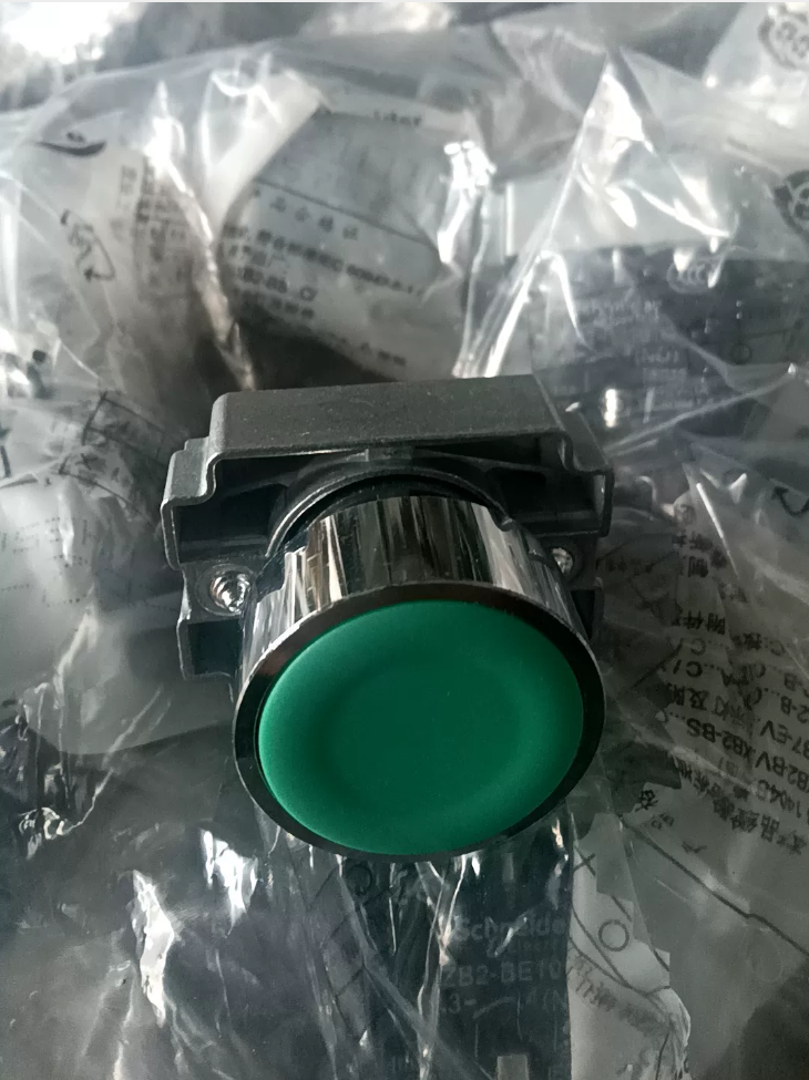
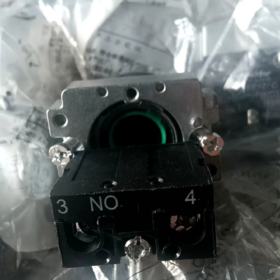
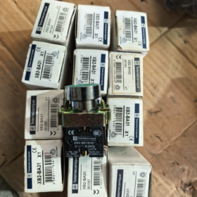
XB2-BA31C (Modèle de commande complet; suffixe “C” ne peut être omis)
XB2: Harmonie XB2, 22 mm série de boutons-poussoirs en métal
BA: Tête affleurante, bouton-poussoir à ressort de rappel
3: Vert
1: 1 Contact normalement ouvert (1NON)
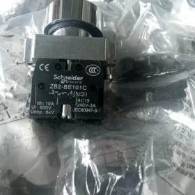
Répartition des composants: ZB2BA3C (tête de bouton poussoir) + ZB2BZ101C (1PAS de bloc de contact)
- Principales spécifications techniques
| Article | Paramètre |
| Diamètre de découpe de montage | Découpe du panneau standard Φ22 mm |
| Type d'opération | Retour du printemps (momentané, rebondit automatiquement dès la libération) |
| Couleur du bouton-poussoir | Vert (bouton-poussoir de démarrage standard) |
| Configuration des contacts | 1NON (Normalement ouvert, bornes 3-4) |
| Matériau de la lunette | Métal chromé, résistant aux chocs |
| Indice de protection | IP65 (côté panneau avant) |
| Courant thermique nominal | 10 UN, tension assignée d'isolement Ui = 600 V |
| Endurance mécanique | ≥ 3 millions d'opérations |
| Température de fonctionnement | -25 ℃ ~ +55 ℃ |
| Type de câblage | Connexion par borne à vis |
- Applications typiques
Bouton-poussoir de démarrage pour armoires de commande industrielles: démarrage du moteur, déclenchement du fonctionnement de l'équipement, circuits de commande de jogging.
Référence correspondante: Bouton poussoir d'arrêt rouge XB2-BA42C (1Caroline du Nord)
- Boutons-poussoirs encastrés communs de la même série
XB2-BA11C: Blanc, 1NON
XB2-BA21C: Noir, 1NON
XB2-BA31C: Vert, 1NON (ce modèle)
XB2-BA41C: Rouge, 1NON; XB2-BA42C: Rouge, 1Caroline du Nord
XB2-BA51C: Jaune, 1NON
XB2-BA61C: Bleu, 1NON
- Notes d'installation
- Épaisseur de panneau applicable: 1~6mm
- Couple de serrage recommandé pour l'écrou de montage: 0.8 N·m
- Pour des contacts supplémentaires, pile ZB2-BE101 (NON) / ZB2-BE102 (Caroline du Nord) modules de contacts
- Ce modèle n'a pas de voyant intégré; pour bouton-poussoir de démarrage éclairé en vert, sélectionnez la série XB2BW33C
Procédure d'installation complète pour Schneider XB2-BA31C (XB2-BA31)
Composition des composants: ZB2BA3C (tête de bouton-poussoir affleurante verte) + ZB2BZ101C (1PAS de bloc de contact)
Conditions préalables & Outils
- Exigences du panneau
Découpe standard: Φ22 mm, découpe ébavurée sans arêtes vives
Épaisseur de panneau applicable: 1~6mm
Espacement minimum entre les boutons-poussoirs adjacents: ≥ 30 mm
- Outils requis
Tournevis plat (PH1), pince à dénuder; tournevis dynamométrique recommandé
- Valeurs de couple standard officielles
Écrou de montage du bouton-poussoir: 0.8 N·m (Ne serrez PAS trop)
Vis de borne: 0.5~0,8 N·m
- Spécification du câble
Câble de commande en cuivre toronné recommandé de 0,5 ~ 1,5 mm², longueur de dénudage 7 ~ 10 mm
Séquence d'installation standard étape par étape
⚠️ Première étape pour tous travaux électriques: Couper l'alimentation principale de l'armoire de commande, mettre en œuvre le verrouillage & étiquetage!
Étape 1: Inventaire des pièces & Inspection visuelle
Vérifier l'ensemble complet après le déballage:
- Tête de commande à bouton-poussoir verte ZB2BA3C (équipé d'un joint d'étanchéité pour assurer une protection IP65)
- Écrou de blocage en métal
- Bloc de contacts ZB2BZ101C (1NON)
Vérifiez que le joint d'étanchéité est intact et que les loquets en plastique sont exempts de fissures..
Étape 2: Insérez la tête du bouton-poussoir dans le panneau de commande (Installer depuis l'AVANT du panneau)
- Monter correctement le joint d'étanchéité sur l'épaulement arrière de la tête du bouton-poussoir (le joint ne peut pas être omis ou tordu)
- Insérez la tête du bouton-poussoir dans la découpe de Φ22 mm depuis l'extérieur. (devant) côté du panneau
- La tige filetée s'étend du panneau arrière; garder la tête du bouton-poussoir étroitement attachée à la surface du panneau sans inclinaison
Étape 3: Monter l'écrou de blocage pour fixer la tête du bouton-poussoir
- Vissez l'écrou de blocage métallique sur la tige filetée depuis l'arrière., serrer à la main jusqu'à ce qu'il touche le panneau
- Serrer uniformément avec l'outil, maintenir le couple à 0.8 N·m
✅ Critères d'acceptation: Bouton-poussoir sans oscillation, pressage doux sans bourrage
❌ N'appliquez pas de force excessive! Un serrage excessif risque de fissurer le joint d'étanchéité., provoquer le grippage du bouton-poussoir et annuler la protection IP65.
Étape 4: Bloc de contact à encliquetage (Point d'erreur d'assemblage le plus fréquent)
- Deux loquets élastiques sur le côté avant du bloc de contact s'alignent avec les fentes à l'arrière de la tête du bouton-poussoir.
- Pousser le bloc de contact horizontalement et droit; deux audibles “cliquez” les sons confirment l'engagement complet des deux loquets
❗ Ne faites pas levier en diagonale et ne forcez pas en appuyant violemment.; les loquets cassés nécessitent le remplacement du bloc de contact
✅ Méthode de suppression: Soulever doucement les deux loquets latéraux avec un tournevis plat et tirer le bloc de contact vers l'arrière.
Étape 5: Opération de câblage (XB2-BA31, 1AUCUN contact)
Marquage des bornes imprimé sur le bloc de contacts:
Terminaux 3, 4 = Normalement ouvert (NON): Circuit ouvert au repos, fermé lorsqu'on appuie dessus
- Dénuder l'isolation des câbles, éviter les brins de cuivre lâches et les bavures
- Insérez le conducteur dans le trou du terminal; assurez-vous que l’isolant n’est pas coincé sous la vis
- Serrer la vis de la borne dans le sens des aiguilles d'une montre (couple 0,5~0,8 N·m)
- Test de traction léger sur le câble pour confirmer l'absence de jeu; les brins de cuivre exposés peuvent entraîner un risque de court-circuit
Étape 6: Test mécanique avant la mise sous tension (Procédure obligatoire)
- Appuyer plusieurs fois sur le bouton-poussoir: bon fonctionnement, rebond automatique instantané après relâchement, pas de grippage ni de bruit anormal
- Confirmez visuellement que les loquets du bloc de contact sont entièrement verrouillés pour éviter le détachement sous l'effet des vibrations.
- Vérifiez que le joint d'étanchéité s'adapte uniformément au panneau, sans espaces. (critique pour la poussière & résistance à l'eau)
Étape 7: Test de continuité avant mise sous tension
Utiliser le mode continuité du multimètre pour tester les bornes 3 et 4:
État de repos: Circuit ouvert (résistance infinie)
Appuyer et maintenir le bouton-poussoir: Conducteur (résistance proche de 0 Oh)
Ne procédez à la mise sous tension qu'après avoir réussi le test.
Référence de câblage typique (Circuit de démarrage standard)
Alimentation de contrôle → Borne 3
Terminal 4 → Bobine du contacteur / Entrée numérique API
Bouton poussoir enfoncé → Bornes 3-4 conduire, signal de démarrage déclenché
Erreurs d'installation courantes & Avertissements
- Manquant / joint d'étanchéité déformé → Perte de l'indice IP65; la pénétration de poussière et d'humidité entraîne une oxydation de contact et une mauvaise conductivité
- Couple excessif sur l'écrou de fixation → Mécanisme interne comprimé, le bouton-poussoir ne parvient pas à rebondir
- Bloc de contact à forcer en diagonale → Fracture des loquets en plastique; le bloc de contact peut tomber pendant le fonctionnement de l'équipement
- Câble trop dénudé et brins de cuivre lâches → Risque de court-circuit entre bornes adjacentes
- Découpe du panneau supérieure à Φ22,2 mm → Le bouton-poussoir vacille et l'étanchéité échoue
- Ne montez pas d'abord le bloc de contacts, puis faites passer le bouton-poussoir à travers le panneau.! Séquence correcte: Fixez d'abord la tête du bouton-poussoir au panneau., puis fixez le bloc de contact
Procédure de démontage (Pour contacter l'entretien & remplacement)
Couper l'alimentation → Soulever les deux loquets du bloc de contact avec un tournevis plat → Tirer le bloc de contact vers l'arrière;
Pour supprimer le bouton-poussoir complet: Dévisser l'écrou de blocage arrière, extraire la tête du bouton-poussoir de la façade du panneau.
Principe de fonctionnement du Schneider XB2-BA31C (XB2-BA31)
Composition des composants: ZB2BA3C (tête de bouton-poussoir à ressort de rappel verte) + ZB2BZ101C (1PAS de bloc de contact)
Il s'agit d'un bouton-poussoir mécanique momentané sans voyant lumineux.
- Principe de fonctionnement mécanique
- État initial (Non pressé)
Le ressort de compression intégré pousse la tête de commande vers l'extérieur et maintient la position étendue. Le contact mobile interne est séparé du contact fixe.
- État d'actionnement (Bouton poussoir)
Une force externe enfonce la tête du bouton-poussoir vert → La tige de poussée interne se déplace vers l'arrière → Entraîne le pont de contact mobile à l'intérieur du bloc de contact pour le déplacer
Le pont de contacts connecte simultanément deux contacts fixes, bornes 3 et 4 (NON) fermé.
- État de sortie (Retour automatique)
Quand la pression externe disparaît, le ressort intégré rebondit et réinitialise la tige de poussée; Le pont de contact se rétracte, les contacts se séparent à nouveau, circuit entre 3 et 4 ouvre.
Caractéristiques: Type momentané (opération de jogging), sans verrouillage; conducteur uniquement lorsqu'il est pressé.
- Principe électrique (XB2-BA31: 1NON Normalement Ouvert)
Marquage des bornes sur le bloc de contacts: 3, 4 = Normalement ouvert (NON)
Statut statique: Circuit ouvert entre 3 et 4 (résistance infinie)
Bouton poussoir: Circuit fermé entre 3 et 4
À la sortie: Le circuit restaure instantanément l'état ouvert
Les contacts sont des contacts secs mécaniques passifs:
Pas d'alimentation intégrée; active/désactive uniquement les circuits de commande externes. Compatible avec les boucles de contrôle AC/DC basse tension (bobines de contacteur, Entrées DI API, circuits relais).
- Brève ventilation de la structure interne
- Boîtier de bouton-poussoir + ressort de retour
- Tige de transmission (transmettre la force de pression)
- Bloc de contacts: Contacts fixes fixes + pont de contact conducteur mobile
- Bornes de câblage à vis
Séquence de transmission de force:
Appui manuel → Tête de bouton-poussoir → La tige de poussée comprime le ressort → Déplacement du pont de contact → Contacts fermés
Bouton de relâchement → Le ressort s'étend et se réinitialise → Le pont de contact recule → Contacts ouverts
- Caractéristiques clés
- Pas de voyant intégré, aucune alimentation d'éclairage requise; distinguer du modèle lumineux XB2BW33C.
- Commutation de contact mécanique physique pure sans composants électroniques, forte performance anti-interférence.
- La protection IP65 repose sur un joint d'étanchéité avant pour empêcher la vapeur d'eau et la poussière de pénétrer dans la cavité de contact..
- Logique d'application typique (Exemple de circuit de démarrage du moteur)
Contrôle en direct L → Terminal 3
Terminal 4 → Bobine KM du contacteur → Neutre N
Lorsque XB2-BA31C est enfoncé → la bobine KM est alimentée, le contacteur s'enclenche;
Le circuit du bouton-poussoir s'ouvre lors du relâchement, fonctionnement continu maintenu par auto-verrouillage via contact auxiliaire NO du contacteur.
Malentendus courants
❌ Pas de bouton-poussoir à verrouillage: Le circuit s'ouvre après la libération, ne peut pas maintenir l'état de conduction
❌ Ne convient pas comme fin de course sous compression continue; accélère la fatigue du printemps
❌ Les contacts servent uniquement aux circuits de commande, ne peut pas piloter directement des charges de forte puissance





NH42-63-318x560.png "Commutateurs de transfert automatiques de type PC CHINT (ATS)NH42-63/4SZ")



