 Contacteur,disjoncteur,capteur,Encodeur,API,Convertisseur


Correction orthographique: TÉLÉPHONE → Contact Phénix
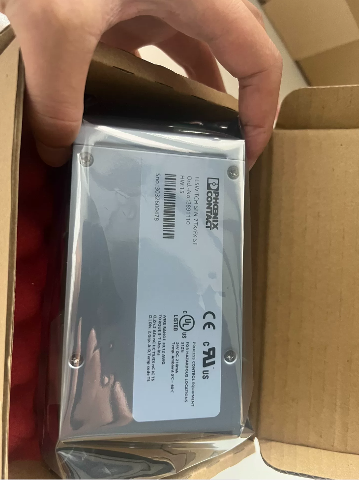
Numéro de commande: 2891110 | Modèle: COMMUTATEUR FL SFN 8GT
Décodage du code modèle
| Segment de code | Signification |
| FL | Ligne d'usine commutateur Ethernet industriel série |
| CHANGER | Commutateur Ethernet |
| SFN | Fonctionnalité standard Commutateur non géré |
| 8GT | 8-port Gigabit RJ45 |
Matériel de base & Spécifications électriques
| Article | Caractéristiques |
| Ports | 8 × RJ45 Gigabit (10/100/1000BASE‑T) |
| Type de commutateur | Switch Ethernet industriel plug-and-play non géré |
| Alimentation | CC 24 V (18-30 V CC), deux entrées d'alimentation redondantes |
| Consommation d'énergie | Max.. 7.5 W |
| Enceinte | Boîtier métallique, Montable sur rail DIN |
| Température de fonctionnement | -40 ℃… +70 ℃ |
| Température de stockage | -45 ℃… +85 ℃ |
| Protection contre la pénétration | IP30 (Pour installation à l'intérieur de l'armoire uniquement) |
| Certifications | CE, UL 61010‑1, C‑UL, ATEX, etc.. |
| MTBF | Environ. 3.5 millions d'heures |
Analyse approfondie des principes de fonctionnement
Il s'agit d'un commutateur Ethernet industriel non géré de couche 2:
- Fonctionne automatiquement après la mise sous tension, aucun logiciel de configuration requis.
- Auto-apprentissage de l'adresse MAC interne, transfert à vitesse filaire pour les trames Gigabit Ethernet entre les ports.
- Prend en charge Auto-MDI-X; les câbles Ethernet droits et croisés sont applicables.
- Double entrée d'alimentation pour la redondance de l'alimentation; le commutateur continue de fonctionner lorsqu'un chemin d'alimentation tombe en panne.
- Pas d'interface WEB ni de console CLI; VLAN, Les fonctions de QoS et de gestion d'anneau ne sont pas prises en charge.
Dimensions d'installation & Définition du câblage
Montage: Montage clipsable sur rail DIN 35 mm; le montage mural à vis est également pris en charge
Dimension logement: L 50 mm × H 130 mm × P 115 mm
Bornes de puissance: 2-bornes à ressort, `L+` pour positif, `M` pour négatif; deux chemins d'alimentation sont indépendants pour la redondance.
Indicateurs LED: Link/Act pour chaque port; LED d'état de l'alimentation.
Câblage des avertissements de ligne rouge:
- N'alimentez jamais le courant alternatif 220 V directement dans les bornes d'alimentation 24 V..
- Indice IP30: Ne pas exposer à l'humidité ou à la poussière dans des environnements à l'air libre; installer uniquement à l'intérieur des armoires de commande.
- Connectez le boîtier métallique à la terre de protection PE de l'armoire pour supprimer les interférences EMI industrielles.
Options de remplacement compatibles
| Modèle OEM d'origine | Modèle de remplacement à ajustement direct | Remarques |
| 2891110 COMMUTATEUR FL SFN 8GT | 2891143 FL‑SWITCH‑SFNB‑8GT | Compatible matériel broche à broche; logements nouvelle génération; direct sur rail DIN interchangeable |
| COMMUTATEUR FL 1008N (2701497) | Switch non géré Gigabit à 8 ports économique; différence dimensionnelle mineure; Montable sur rail DIN |
⚠️Avis de risque: Vérifiez le dégagement d'installation et la consommation électrique des unités de remplacement.. Prioriser le modèle 2891143 pour la mise à niveau de projets existants pour une compatibilité totale des broches.
Contenu du paquet
Articles de livraison standard:
- Unité hôte FL-SWITCH-SFN-8GT ×1
- Clip de montage sur rail DIN préinstallé
- Manuel d'installation papier
Articles NON inclus (commander séparément):
24 Alimentation V CC
Fiches à bornes à ressort
Câbles Ethernet
Scénarios d'application typiques
- Mise en réseau Gigabit interne à l'armoire de commande pour les automates, servomoteurs et panneaux IHM (machines d'emballage, industrie des machines-outils).
- Switch d'agrégation pour modules d'E/S de terrain distribuées sur les lignes de production.
- Réseau local à l'intérieur d'armoires pour le stockage d'énergie photovoltaïque, automatisation portuaire et équipements de transit ferroviaire.
❌Scénarios non applicables: Projets nécessitant une segmentation VLAN ou une redondance de réseau en anneau. Sélectionnez plutôt des commutateurs gérés tels que la série FL SWITCH 2xxx.
Guide des pièges de la sélection des modèles
- Il s'agit d'un commutateur non géré sans redondance en anneau ni fonctions VLAN; ne sélectionnez PAS ce modèle pour les exigences de topologie en anneau.
- Température de fonctionnement: -40~+70°C. Maintain adequate clearance for heat dissipation in high-temperature cabinets; avoid stacking multiple units inside enclosed narrow compartments.
- Copper-port-only gigabit unit; no optical ports. Select variants with SFP slots if fiber extension is needed.
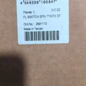
Contact Phénix 2891110 (FL SWITCH SFN 7TX/FX-ST) Cas de candidature
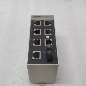
Présentation du produit: 7 × RJ45 100 Mbps copper ports +1 × ST multi-mode 100 Mbps fiber port, unmanaged DIN-rail industrial switch. Core values: Optical-electrical conversion, long-distance fiber extension, plug-and-play zero-configuration.
Cas 1: Automotive Component Assembly-Line Cabinet (PROFINET Field-Level Aggregation)
Conditions de fonctionnement: Assembly line located approx. 800 m away from central control room. Heavy EMI from frequency converters; multiple servo drives, vision cameras, HMI panels and distributed I/O units. Twisted-pair copper cable is limited to 100 m, la fibre optique est donc nécessaire pour l'isolation galvanique et la transmission longue distance.
Connexion matérielle: 7 Les ports RJ45 connectent l'API, 3 ensembles de servomoteurs, IHM, 2 unités de vision-inspection et modules d'E/S déportées. Le port fibre ST est relié à la fibre multimode pour une liaison montante vers le commutateur principal central.
Justification de la sélection:
- Configuration zéro non gérée; les unités pré-mises en service peuvent être déployées directement à l'intérieur des armoires.
- La fibre multimode ST offre une immunité EMI élevée et élimine les interférences de mode commun des câbles d'alimentation.
- Boîtier sur rail DIN étroit de 50 mm pour les armoires de commande à espace limité.
- Conforme PROFINET Classe A; La QoS donne la priorité aux trames de contrôle en temps réel.
Note de limite: 100 Mbit/s seulement, adapté au trafic de contrôle de processus. Sélectionnez des modèles Gigabit pour le streaming de vision haute résolution à large bande passante.
Cas 2: Sous-station PLC sur le terrain d'une usine de traitement d'eau (Interconnexion entre les stations de pompage souterraines et la salle de contrôle centrale)
Conditions de fonctionnement: Stations de pompage décentralisées dans toute l’usine; les armoires de la station de pompage se trouvent à 600-1 200 m du bâtiment de contrôle central. Environnement humide avec de grandes fluctuations de température; EMI lourdes provenant de moteurs de pompe haute puissance.
Topologie du réseau: Un 2891110 déployé dans chaque armoire de station de pompage. Les ports RJ45 connectent l'automate local, débitmètres, analyseurs et passerelles de qualité de l'eau. La fibre multimode ST fournit une liaison montante point à point vers le commutateur de la salle de contrôle centrale.
Points douloureux résolus:
- Les câbles en cuivre ne peuvent pas couvrir de longues distances à l'échelle de l'usine. La fibre fournit une isolation galvanique et élimine les interférences de boucle de terre.
- 0La plage de fonctionnement d'environ 60 °C s'adapte aux variations saisonnières de température de l'armoire à l'intérieur des stations de pompage..
- Aucune configuration logicielle requise; le personnel de maintenance sur site n'a pas besoin d'une expertise professionnelle en matière de réseau.
Note: Distance de transmission maximale de la fibre ST multimode env.. 2 kilomètres. Utilisez des variantes de port fibre monomode pour des distances plus longues.
Cas3: Atelier auxiliaire d'aciérie métallurgique (Dépoussiérage & Armoires pour convoyeurs)
Conditions de fonctionnement: Lignes auxiliaires d'aciéries, poussière importante et fortes interférences électromagnétiques. Plusieurs armoires locales situées à 500-900 m de la salle de contrôle principale; Protocoles Modbus-TCP et EtherNet/IP déployés.
Déploiement: Montage sur rail DIN à l'intérieur d'armoires locales. 7 les ports en cuivre connectent le PLC, convertisseurs de fréquence et modules d'acquisition de température. Liaisons montantes du port fibre ST vers la salle de contrôle principale.
Points clés de sélection: Boîtier robuste en métal et aluminium, haute immunité CEM conforme à EN61000-6-2. Les contacts du relais d'alarme peuvent alimenter l'automate de l'armoire pour l'acquisition d'alarme en cas de défaut de commutation..
❌Non applicable: Zones de fusion à haute température dans les aciéries (ambiant >60 °C). Mise à niveau vers la variante SFNT à large température (-40~+75°C).
Cas4: Tunnel utilitaire / Sous-armoires de surveillance de galerie de canalisations
Conditions de fonctionnement: Armoires de terrain segmentées déployées le long des tunnels de services publics. Les armoires hébergent des automates de surveillance environnementale, passerelles d'alarme incendie et caméras NVR; fibre en cascade vers le centre de contrôle.
Déploiement: Un 2891110 installé par armoire de segment tunnel. Les ports RJ45 connectent les appareils d'acquisition sur le terrain. Le port fibre ST effectue une mise en cascade de fibre segmentée.
Rappel de contrainte: Il s'agit d'un commutateur non géré, sans redondance de réseau en anneau.. Ne formez pas d'anneaux de fibres directement; utiliser la série gérée FL SWITCH 2xxx pour les exigences d'auto-réparation en anneau. Seules les liaisons montantes fibre optique point à point à topologie en étoile sont autorisées..
Cas5: Grand entrepôt automatisé (Armoires pour unités de tri périphériques)
Conditions de fonctionnement: Zones de tri des entrepôts à hauts rayonnages env.. 700 m de la salle des serveurs centrale. Grande quantité de lecteurs de codes-barres, sorting-line PLCs and pallet-position sensors.
Déploiement: DIN-rail installation inside sorting-unit cabinets. 7 copper ports aggregate field Ethernet devices. ST fiber uplinks to core switch in server room for surge isolation from high-power equipment.
Avantages: Plug-and-play operation, standardized hardware across sorting-unit cabinets; unified BOM reduces spare-part types.
Model-Selection Lessons from Real-World Projects
- Fiber port supports only 100 Mbps, ST multi-mode, maximum. distance approx. 2 kilomètres. Gigabit traffic cannot pass through this port. Do not connect gigabit-capable devices expecting gigabit throughput.
- Unmanaged unit: No ring support, no VLAN, no STP. Only star-topology point-to-point uplinks permitted. Never build fiber rings.
- Keep ST fiber connectors dust-protected; install dust caps on unused ports. Dust causes frame loss and intermittent link dropouts.
- Power supply range: 9-32 VCC. Ne connectez jamais AC220V. Mise à la terre PE obligatoire du boîtier métallique pour la suppression des interférences électromagnétiques.
- Température de fonctionnement du modèle standard 0~60°C. Sélectionnez Numéro de commande. 2891047 (Variante SFNT à large température, -40~+75°C) pour des conditions ambiantes inférieures à zéro ou supérieures à 60°C.
Liste de remplacement compatible pour des conditions de fonctionnement équivalentes
| Modèle original 2891110 | Modèle de remplacement | Description de la différence |
| COMMUTATEUR FL SFN 7TX/FX‑ST | 2891097 COMMUTATEUR FL SFN 7TX/FX | Connecteur fibre de type SC; tous les paramètres électriques identiques; remplacer les cordons de brassage en fibre en conséquence |
| 2891047 COMMUTATEUR FL SFNT 7TX/FX ST‑C | Large plage de températures -40~+75°C pour les environnements extrêmement chauds/froids; entièrement compatible avec les broches |
Contact Phénix 2891110 (FL SWITCH SFN 7TX/FX-ST) Liste de contrôle de dépannage sur le terrain
Spécification de l'appareil: 7 × Ports cuivre RJ45 100 Mbps +1 × ST multi-mode 100 Mbps fiber port, commutateur industriel non géré avec sortie relais d'alarme de défaut.
Pré-requis: Plage d'alimentation 9-32VDC. Le boîtier métallique doit être connecté à la terre de protection PE. Fibre multimode ST uniquement; gigabit non pris en charge.
Définition des indicateurs LED
| DIRIGÉ | Statut | Signification |
| REP1 / REP2 | Vert uni | Chemin d'alimentation correspondant OK; OFF = perte de puissance |
| LIEN/AGIR (Port en cuivre) | Solide | Lien établi; Clignotant = transmission/réception de données; OFF = pas de lien |
| LIEN/AGIR (Port fibre FX) | Vert uni | Liaison fibre établie; Clignotant = trafic de données fibre; OFF = liaison fibre coupée |
| FAUTE (Faute) | Rouge uni | Relais d'alarme activé; OFF = appareil normal |
Relais DEFAUT: Relais passif à contact sec. Le relais se déclenche en cas de perte d'alimentation OU de toute liaison de port en panne. Peut se connecter au canal d'entrée numérique PLC pour une alarme au niveau du système.
Défaut1: Unité complètement hors tension; toutes les LED éteintes
- Mesurer la tension continue aux bornes « L+ » et « M ». Confirmer la tension entre 9 et 32 V CC. Vérifiez la polarité correcte; l'inversion de polarité est interdite.
- Au moins un des doubles PWR1/PWR2 redondants doit être alimenté. Une alimentation nulle sur les deux chemins entraîne un arrêt complet.
- Inspecter les bornes à ressort pour un couple serré; vérifier s'il y a des brins lâches provoquant un court-circuit.
- Condition aux limites: La protection contre la surchauffe déclenche l'arrêt si la température ambiante de l'armoire dépasse 60 °C. Maintenir un dégagement ≥20 mm pour la ventilation. Évitez de les empiler dans des compartiments scellés.
❗Avertissement de ligne rouge: AC220V connecté aux bornes d'alimentation détruira définitivement le matériel.
Défaut2: LED d'alimentation allumées, mais tous les indicateurs de port LINK sont éteints
- Ports en cuivre: Utilisez un câble Ethernet de 100 Mbps vérifié et en bon état. Auto-MDI-X est pris en charge.
- Forcer le réglage de la vitesse du port du périphérique distant à 100 Mbps en duplex intégral. Ne forcez PAS le gigabit. Une négociation forcée par gigabit mal adaptée empêchera la liaison.
- Port fibre: Retirez le connecteur ST et nettoyez l'extrémité de la fibre.; retirer le capuchon anti-poussière s'il est laissé installé. Confirmer que la fibre multimode est utilisée. La fibre monomode ne peut pas activer cet émetteur-récepteur optique.
- Exigence de croisement fibre TX-RX: Le commutateur TX doit se connecter à l'unité distante RX; le commutateur RX doit se connecter à l'unité distante TX. Un mauvais câblage entraîne une liaison sans fibre.
Défaut3: Perte de trame aléatoire du trafic sur le port cuivre, liaison ascendante-descendante intermittente
- Atténuation des interférences électromagnétiques: Câbles d'alimentation séparés (onduleurs, fils d'alimentation du moteur) et câbles Ethernet avec un dégagement physique ≥20 mm.
- Assurer une connexion solide de protection PE du boîtier métallique. Une mauvaise mise à la terre induit un bruit de mode commun provoquant une perte aléatoire de paquets.
- Longueur du câble en cuivre limitée à max. 100m. Inspecter la qualité du sertissage des fiches RJ45. Pour câbles blindés: appliquer une mise à la terre de blindage à une extrémité.
- Ne connectez pas d'appareils Gigabit forcés. Forcer le réglage du port distant sur 100 Mbps en négociation automatique ou 100 Mbps en duplex intégral.
Défaut4: Port fibre FX sans LINK; les ports en cuivre fonctionnent normalement
- Confirmer 50/125 ou 62.5/125 fibre multimode à terminaison ST. Ce port ne prend pas en charge la fibre monomode.
- Nettoyer les extrémités des fibres. La poussière est la cause première des défauts des ports fibre sur site. Installez des capuchons anti-poussière sur les ports fibre inutilisés.
- Valider le câblage croisé TX-RX: Commutation TX ↔ RX à distance.
- Validation à distance: Max.. atteindre env. 2km pour 62.5/125 multimode 100BASE-FX. Les liens échoueront au-delà de cette distance.
- Test de santé de l'émetteur-récepteur: Appliquer une fiche de bouclage de fibre courte au port de fibre local. Si la LED FX-LINK s'allume, le matériel de l'émetteur-récepteur local est intact; la faute réside dans l’infrastructure de fibre externe.
Défaut5: La LED rouge FAULT reste allumée en alarme, mais la communication réseau reste fonctionnelle
Conditions de déclenchement du relais DEFAUT: Toute liaison de port en panne OU perte d'une alimentation redondante. Cette alarme n'équivaut PAS à une panne matérielle.
- Inspectez les LED LINK/ACT de chaque port cuivre et fibre.; identifier les ports avec un lien manquant.
- Vérifiez les LED d'alimentation PWR1/PWR2 pour identifier tout chemin d'alimentation perdu.
- Réparer les câbles/fibres défectueux pour les ports en panne. Aucune fonction logicielle disponible pour supprimer les alarmes de port inutilisé sur ce commutateur non géré. Retirez les câbles des ports inutilisés pour effacer les alertes de DÉFAUT persistantes.
Remarque importante: Le matériel non géré ne peut pas désactiver les alarmes par port. Les ports non câblés déclenchent en permanence l'état FAULT, quel est le comportement attendu.
Défaut6: Appareils partiels inaccessibles; échec de communication interport
- Commutateur plug-and-play de couche 2 avec transfert complet de port à port par défaut. Aucune capacité de configuration VLAN.
- Vérifiez que tous les appareils finaux résident dans un sous-réseau IP identique.
- Vérifiez les paramètres du pare-feu local sur les automates et les hôtes connectés pour connaître les règles de filtrage des paquets..
- Prévenir les boucles réseau: Ne créez jamais de topologie en boucle fermée via des câbles en cuivre ou en fibre dans ce commutateur; les tempêtes de diffusion feront planter tout le réseau.
Opérations sur le terrain strictement interdites (Tabous de la ligne rouge)
- Ne connectez pas d'appareils distants forcés à une vitesse gigabit. Ce matériel est strictement constitué de ports cuivre 100 Mbps; un échec de négociation se produit.
- Ne déployez pas de fibre monomode sur ce port optique multimode: Pas d'établissement de lien, dommages potentiels à l'émetteur-récepteur optique.
- Installez toujours des capuchons anti-poussière sur les ports fibre ST inutilisés.. La contamination de l'extrémité entraîne un taux de défaillance élevé.
- Le relais d'alarme est à contact sec passif. N'appliquez jamais AC220V directement aux bornes de relais. Connectez-vous uniquement aux circuits d'entrée PLC DC24V.
- Indice IP30: Pour utilisation en armoire uniquement. Pas de plein air, installation en milieu humide.
- N'empilez pas plusieurs interrupteurs dans des armoires étroites et hermétiques.. Une surchauffe entraînera une limitation ou un arrêt de protection.
Flux de travail de diagnostic rapide sur site (Pour les techniciens de terrain)
- Inspecter les LED PWR: Confirmez qu'au moins un chemin d'alimentation est actif.
- Inspecter la LED DE PANNE: Rouge allumé → Localisez le chemin d'alimentation perdu ou le port de liaison vers le bas.
- Dépannage des pannes du port cuivre: Remplacer le câble en bon état; forcer le port distant à 100 Mbps en duplex intégral.
- Dépannage des pannes du port fibre: Nettoyer l'extrémité ST; vérifier le croisement TX-RX; confirmer le type de fibre multimode.
- Valider la mise à la terre PE; câblage d'alimentation et de signal séparé pour résoudre les symptômes aléatoires de perte de paquets.




NH42-63-318x560.png "Commutateurs de transfert automatiques de type PC CHINT (ATS)NH42-63/4SZ")



