 Contacteur,disjoncteur,onduleur solaire,compteur électrique,batteries solaires

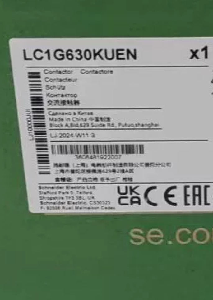

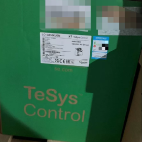
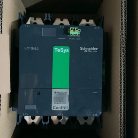
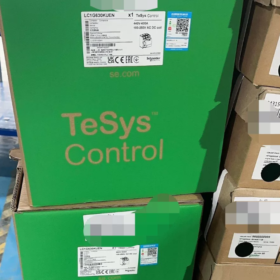
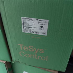
Full Model Number: LC1G630KUEN
Marque: Schneider Électrique
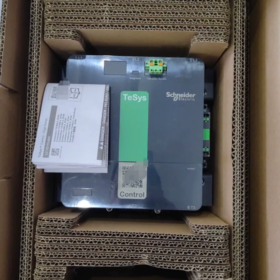
Série: TeSys Giga New Generation High-Current Contacteur CA (Replaces Legacy LC1F630)
Statut du produit: Mass-produced, in stock, global standard imported version
Application: Direct-on-line starting of high-power motors, contournement du démarreur progressif, commutation de puissance de jeu de barres, contrôle d'équipements lourds tels que les compresseurs d'air, laminoirs et ponts roulants
Model Code Decoding `LC1 G 630 KUEN`
- LC1: Standard 3-pole AC contactor
- G: TeSys Giga high-current platform
- 630: Rated operational current 630A at AC-3, 440V
- KU: Electronic wide-voltage coil code (KUE = 100~250V AC/DC universal coil)
- E: Global imported version (distinguished from domestic “C” suffixe)
- N: Standard base unit (no special extended or downgraded structure)
- Core Electrical Ratings
2.1 Main Contact Ratings
| Catégorie d'utilisation | Tension nominale | Courant nominal | Matching Motor Power |
| AC-3 (Motor Switching) | 440V et | 630UN | 400kW |
| AC-1 (Resistive / By-pass) | ≤1000V AC | 1050UN | Resistive heating, contournement du démarreur progressif |
| Tension d'isolement nominale Ui | 1000V | Short-Time Withstand Current Icw | 5.05le / 10s |
| Capacité de coupure | 5550A at 440V | Connexion du circuit principal | Bolted busbar connection |
2.2 Control Coil (Key Features of KU Version)
Plage de tension de bobine: 100~250V AC/DC universal for AC and DC supply
Low-power electronic coil with built-in surge suppression; no additional RC snubber required
Pick-up time ≈70ms, drop-out time ≈50ms
Wide voltage range supports direct PLC driving and reduces cabinet heat generation
2.3 Contacts auxiliaires (Standard Non-Removable)
Fixed built-in 1NO + 1Contacts auxiliaires NF
Minimum load: 17V / 1mA (compatible with low-current PLC feedback signals)
- Mécanique, Dimensional & Spécifications environnementales
- Dimensions hors tout: H 324mm × W 210mm × D 266mm
- Unit Weight: 14.2kilos
- Endurance mécanique: 5,000,000 opérations; Endurance électrique (AC-3): 600,000 opérations
- Fréquence de fonctionnement maximale: 600 cycles par heure
- Classe de protection: IP2X with front protective cover
- Température ambiante de fonctionnement: -25℃ ~ +60℃ (no current derating at 60℃ full load)
- Température de stockage: -60℃ ~ +80℃
- Altitude: No derating required up to 3000m
- Montage: Flat wall mounting, supports installation at any angle
- Exclusive Core Functions (Standard for TeSys Giga Series)
- CWD Main Contact Wear Self-Diagnosis
Front panel LED indicator identifies faults via flash counts:
1 éclair: Main contact wear warning
2 clignote: Coil undervoltage
3 clignote: Coil overvoltage
Continuous fast flashing: Internal module hardware failure
- Modular Replaceable Main Contact Cartridge
Only the contact cartridge needs replacement after wear instead of the whole unit, greatly lowering maintenance costs.
- Front plug-in spring control terminals; busbar disassembly not required for wiring
- Direct bottom mounting of matching LR9G series thermal overload relays without transition busbars
- QR code on unit body; scan to download complete datasheets, wiring diagrams and certification documents
- Compatible / Remplacement / Same Series Model Comparison
5.1 Direct Replacement for Legacy Model
Discontinued original model LC1F630M7 → Standard replacement LC1G630KUEN
5.2 Same Current Rating with Different Coil Versions
| Suffixe du modèle | Spécification de la bobine | Scénario d'application |
| LC1G630EHEN | 48~130V AC/DC | Low-voltage control circuits |
| LC1G630KUEN | 100~250V AC/DC | Universel (ce modèle) |
| LC1G630LSEN | 200~500V AC | Circuits de commande haute tension |
5.3 Domestic Localized Version
LC1G630KUEC (C = China CCC certification; identical dimensions and functions, only differing in origin and certification)
5.4 4-pole Equivalent Model: LC1G6304KUEN (4 contacts principaux normalement ouverts)
- Typical Fault Matrix
| Symptôme de panne | Cause première | Résolution |
| Coil fails to pull in after power-up, no indicator light | Broken control circuit, coil voltage below 100V | Measure control voltage and inspect wiring terminals |
| Chattering during pull-in, alarm flashes twice | Coil undervoltage, excessive voltage drop from thin control wires | Use thicker control cables and raise supply voltage |
| Pulls in but trips during operation, flashes once | Severe main contact ablation, excessive contact resistance | Replace main contact cartridge |
| Continuous fast LED flashing | Damaged internal electronic control board | Replace the entire contactor |
| Severe overheating during closing | Loose busbar bolts, oxidized contacts | Retighten to specified torque and polish contact surfaces |
- Standard Optional Accessories List
- LA9G630: Interphase arc barrier
- LA9G970: Mechanical interlock for two units (forward/reverse / reversing circuits)
- LA9G3762: Connection busbars for reversing contactors
- LR9G630: Matching thermal overload relay (direct bottom mounting)
- Terminal insulating protective covers, extended busbar transition adapters
- Scénarios d'application typiques
- Direct-on-line starting control for high-power fans, pompes à eau et compresseurs
- Bypass contactors for 160~250kW soft starters
- Heavy-duty motors for overhead travelling cranes, steel rolling and mining equipment
- Busbar switching in low-voltage distribution cabinets, capacitor switching for reactive power compensation (AC-1 duty)
- Heavy-duty industrial control integrated equipment for marine, metallurgy and cement industries
- Approvisionnement & Informations sur les certifications
- Certifications: CE, CCC, cULus, CAE, marine classification society certifications
- Environmental Compliance: Prime verte, mercury-free design complying with RoHS/REACH
- État de l'approvisionnement: Original imported stock available; standard factory lead time 5 semaines
- Couple de câblage: Main circuit bolts torque 80N·m; tool-free direct insertion for spring control terminals
LC1G630KUEN (TeSys Giga) VS LC1F630 (TeSys F) Rénovation & Replacement Comparison Table
- Overall Unit Dimension Comparison (H×L×P)
| Élément de paramètre | LC1F630 (Legacy Model) | LC1G630KUEN (Nouveau modèle) | Retrofit Impact |
| Unit Height H | 304 mm | 284 mm | Height reduced by 20mm, extra space available at cabinet top |
| Unit Width W | 309 mm | 210 mm | Width reduced by 99mm (environ. 35%), significant cabinet space saving |
| Unit Depth D | 255 mm | 266 mm | Depth increased by 11mm; clearance required at rear |
| Net Unit Weight | 18.6 kilos | 14.2 kilos | Weight reduced by 4.4kg, lower load on mounting plate |
- Mounting Plate Hole Dimensions (Standard 3-pole)
2.1 Espacement des trous de montage
| Spécification | LC1F630 | LC1G630KUEN | Retrofit Key Points |
| Horizontal Hole Pitch G (pole-wise spacing) | 90 mm | 70 mm | Old and new holes offset horizontally; original holes cannot be reused |
| Vertical Hole Pitch J (top-bottom spacing) | 220 mm | 242 mm | Vertical spacing increased |
| Fastener Bolt Size | M8 bolt | M8 bolt | Same bolt size but fully misaligned hole positions |
| Max Drill Hole Diameter | 8 mm | 9 mm | New contactor accepts larger mounting holes |
| Number of Mounting Holes | 4 diagonal fixing holes | 4 diagonal fixing holes | Same quantity of holes with fully shifted positions |
- Two Retrofit Solutions for Mounting Plate
1) Direct re-drilling: Mark and drill new holes on existing plate, abandon old holes
2) Add transition steel plate: Prefabricated adapter plate matching original LC1F hole pitch without cabinet plate modification (recommended for mass retrofits)
Schneider original replacement kit LA9GRT630 – dedicated transition bracket compatible with original LC1F mounting holes.
- Main Circuit Busbar / Terminal Interface Comparison
| Article | LC1F630 | LC1G630KUEN | On-Site Wiring Difference |
| Inter-Pole Center Distance | 90mm | 70mm | Busbar span reduced by 20mm; original busbars require re-bending / coupe |
| Terminal Opening Width | 60mm | 48mm | Legacy 60mm-wide busbars cannot be inserted directly into new terminals |
| Max Allowable Busbar Size | 60×5mm | 50×20mm | New model supports thicker double-layer busbars with higher current carrying margin |
| Busbar Layers Per Terminal | Single-layer busbar | Double-layer busbar (standard 52×20mm busbar) | New model allows stacked upper and lower busbars |
| Main Circuit Tightening Torque | 58 N·m | 80 N·m | Higher torque requirement for new bolts; extended torque wrench needed |
| Cable Lug Compatibility | Single 185mm² cable lug | Single 185mm² ring lug | Interchangeable lug size but different front-rear installation positions |
Busbar Retrofit Recommendations
- Original 60mm-wide busbars matched to LC1F: Cut down to 48–50mm width
- Change span from 90mm to 70mm and shorten inter-pole connecting segments
- Prioritize original standard 52×20mm connection busbars LA9G630BUS (no bending required)
- Control Circuit Wiring Differences
| Paramètre | LC1F630 | LC1G630KUEN | Retrofit Notes |
| Control Terminal Type | Screw compression terminals | Front plug-in tool-free spring terminals | Control cables require no crimp lugs; prêt à l'emploi |
| Control Cable Cross-Section | 1~4mm簡 solid / stranded wire | 0.2~2.5mm簡 | Better compatibility for thin signal wires (PLC feedback) |
| Disposition des bornes | Side of unit | Lower front face of unit | No side bending required for easier maintenance access |
| Consommation électrique de la bobine | 1500VA pick-up, 80VA holding | Only 11W holding power | Greatly reduced cabinet temperature rise; no extra cooling fan needed |
| Coil Voltage Compatibility | Single fixed AC/DC rating | KU series universal 100~250V AC/DC | No control transformer replacement required, fits most field circuits |
- Matching Thermal Overload Relay Installation
- LC1F630: LR9F7375, side external mounting with transition busbars required
- LC1G630KUEN: LR9G630, direct bottom plug-in mounting, no transition busbars and smaller overall footprint
- Retrofit Tip: Remove existing external thermal relay bracket, mount thermal relay directly under contactor to shorten wiring length
- Retrofit Risks & Construction Precautions
- Mounting Plate: Old and new hole positions are completely misaligned; do not force contactor fastening. Original transition bracket LA9GRT630 is recommended.
- Main Busbars: Pole spacing reduced by 20mm. Forced assembly of legacy busbars causes terminal stress, overheating and ablation – busbars must be remanufactured.
- Rear Clearance: New model is 11mm deeper. Verify minimum 30mm safety clearance if busbars or cable trunking are installed at cabinet rear.
- Torque Standard: Main circuit torque must reach 80N·m; insufficient torque leads to overheating during long-term operation.
- Control Circuits: Shorten legacy screw-type control wires and insert directly into spring terminals without re-crimping lugs.
- Maintenance Advantage: G-series contact cartridges are replaceable separately, while damaged F-series contactors require full unit replacement for lower long-term maintenance costs.
- Minimal Retrofit Bill of Materials
- Main Unit: LC1G630KUEN
- Mounting Transition Bracket: LA9GRT630 (reuses original LC1F plate holes)
- Relais de surcharge thermique correspondant: LR9G630
- Busbar Accessory: LA9G630 standard connection busbars
- Protection Accessory: LA9G630 interphase arc barrier


, tension de bobine de 110 V AC, et est équipé de 1 Normalement ouvert (1NON) contact auxiliaire")
. Remplacements recommandés: LC1D115KUEC ou LC1E120M5N")


")
NH42-63-318x560.png "Commutateurs de transfert automatiques de type PC CHINT (ATS)NH42-63/4SZ")


