 Contacteur,disjoncteur,capteur,Encodeur,API,Convertisseur

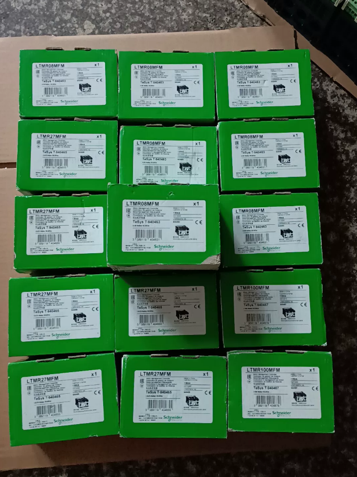

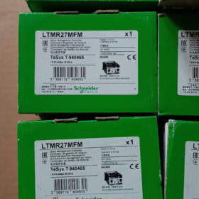
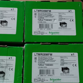
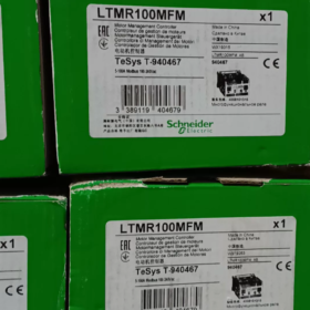
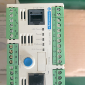
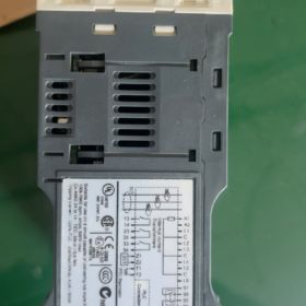
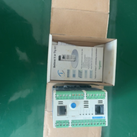
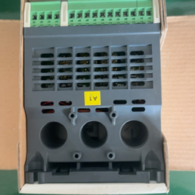
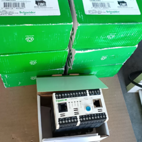
Domaines d'application de Schneider LTMR27MFM (TeSys T)
Note actuelle: 1.35~ Contrôleur de gestion intelligent 27A pour moteurs asynchrones triphasés, équipé de la communication Modbus-RTU. Largement déployé à l'intérieur des armoires MCC pour une protection moteur intégrée, surveillance du courant et transmission des données à distance.
Répartition du code modèle
LTMR27MFM
LTMR: TeSys T contrôleur de gestion moteur unité de base
27: Plage de mesure du courant 1,35 ~ 27 A (transformateurs de courant intégrés)
M.: Interface de communication → Modbus RS485
FM: Alimentation de commande 100~240 VAC (CA)
Référence croisée au sein de la série: LTMR27EFM = Ethernet; LTMR27CFM = CANopen
- Principales spécifications électriques
| Article | Paramètre |
| Plage de courant moteur | 1.35 … 27 UN (TC intégré, aucun transformateur de courant externe requis) |
| Alimentation du contrôleur | 100~240 V CA 50/60 Hz (large tolérance: 93.5~264 V) |
| Communication | Modbus RTU RS485, bornier + Double port RJ45; adresse 1~247; débit en bauds 1,2k~19,2k |
| E/S numériques | 6 entrées numériques; 3 PAS de sorties relais + 1 relais de défaut (1NON+1NC) |
| Valeur nominale du contact du relais | 5A /250VAC; 5Un /30 V CC |
| Montage | Montage sur rail DIN |
| Dimensions hors tout | L91 mm × H61 mm × P122,5 mm; Poids net 0.53 kilos |
| Température de fonctionnement | -20 ℃ ~ +60 ℃; Température de stockage -40 ~ 80 ℃ |
| Classe de protection | IP20 (pour installation à l'intérieur d'une armoire) |
- Fonctions de protection intégrées
✅ Protection contre les surcharges thermiques (modèle thermique)
✅ Perte de phase & 3-protection contre le déséquilibre du courant de phase
✅ Protection du rotor bloqué, protection contre les démarrages longs
✅ Protection contre les sous-charges (surveillance de la marche à sec/de la rupture de courroie)
✅ Protection contre les défauts de terre (TC homopolaire interne ou externe)
✅ Prise en charge de l'entrée de thermistance du moteur PTC
✅ Journalisation des défauts, historique du voyage, compteur d'heures de fonctionnement
- Capacité de mesure (Tension & mesure de puissance avec module d'extension LTME)
Mesure de l'unité de base: 3-courant de phase, courant moyen, courant de déséquilibre, courant de défaut à la terre;
Lorsqu'il est équipé d'un module d'extension LTME: tension triphasée supplémentaire, puissance active/réactive, facteur de puissance, comptage d'énergie.
- Logiciel de mise en service
Configuration via le logiciel SoMove (TeSys T DTM). Connectez le PC directement via le port HMI RJ45 avant pour le réglage des paramètres, lecture des défauts et surveillance en temps réel.
Panneau d'affichage local en option: LTMCU / LTMCUF.
- Avis sur le cycle de vie
La série complète LTMR TeSys T est en cours d'élimination (EOL).
Date limite officielle de commande: 30 Sep 2026; Fin du support technique: 31 Jan 2027
Remplacement de nouvelle génération: TeSys Tera
Unité principale: LTMTMFM (Modbus, 100~240 VCA/CC)
Faire correspondre le capteur de courant:
2.5~25A → LTMTCTV25UT (correspondance la plus proche pour l'application originale 1,35 ~ 27A)
⚠️ Le schéma de câblage et le mappage des registres Modbus ne sont pas entièrement compatibles entre les anciennes et les nouvelles séries. La modernisation sur site nécessite la remise en service du programme.
- Application typique
Centres de contrôle de moteurs MCC, pompes à eau, les fans, compresseurs, convoyeurs; projets en traitement de l'eau, CVC, industries métallurgiques et cimentières.
- Distinction rapide des modèles similaires
LTMR27MFM:1.35~27A, Modbus, 100~240 VCA
LTMR100MFM:5~100A, Modbus, 100~240 VCA
LTMR27EFM:1.35~27A, Ethernet/IP
Principaux segments de l'industrie
- Approvisionnement en eau municipal & Traitement des eaux usées (Application la plus courante)
✅ Stations d'épuration municipales, aqueduc, stations de pompage
✅ Charges typiques: pompes submersibles, pompes centrifuges, pompes de retour de boues, ventilateurs d'aération, grattoirs
Exigences clés satisfaites: protection contre les sous-charges (prévention de la marche à sec), protection contre les défauts à la terre, alarme de défaut à distance, surveillance de l'énergie.
- CVC, Bâtiments commerciaux & Systèmes électromécaniques du bâtiment
✅ Centres commerciaux, hôpitaux, centres de données, installations de refroidissement de parcs industriels
✅ Charges typiques: pompes à eau glacée, pompes à eau de refroidissement, ventilateurs de tour de refroidissement, ventilateurs d'extraction, Ventilateurs CTA
Avantage: surcharge thermique & protection rotor bloqué; Connexion Modbus au système BA du bâtiment pour les données actuelles et les signaux de défaut.
- Ciment, Matériaux de construction & Lignes de production minière d'agrégats
✅ Convoyeurs à bande, élévateurs à godets, entraînements auxiliaires pour presses à rouleaux, ventilateurs d'extraction de poussière, équipement de déchargement de silo
✅Protection ciblée: protection rotor bloqué, protection contre les démarrages longs, protection contre le déséquilibre des phases pour éviter l'épuisement du moteur causé par un blocage mécanique.
- Chimique & Industrie pharmaceutique
✅ Pompes de circulation, moteurs d'agitateurs, moteurs de compresseur d'air auxiliaire, ventilateurs de poussière
✅ Prend en charge la connexion de la thermistance PTC pour la surveillance de la température des enroulements du moteur; déclenchement rapide en cas de perte de phase et de défauts à la terre pour répondre aux normes de sécurité industrielle.
- Nourriture & Boisson, Lignes de production d'emballages
✅ Moteurs de convoyeurs, souffleurs, pompes de lavage, entraînements de machines d'emballage
Surveillance précise des sous-charges pour détecter le manque de matériau ou le détachement de la courroie; l'historique des pannes facilite la maintenance de la production.
- Transport ferroviaire & Systèmes électromécaniques pour tunnels
✅ Ventilateurs à jet tunnel, pompes de drainage, ventilateurs d'extraction de fumée
Protection fiable pour les moteurs des pompiers; téléchargement de données vers le système de contrôle PLC du tunnel.
- Équipement auxiliaire de centrale électrique
✅ Pompes à eau à circulation, ventilateurs, convoyeurs de manutention de cendres; composant standard à l'intérieur des salles MCC de la centrale électrique.
- Port & Entreposage Logistique
✅ Convoyeurs, entraînements auxiliaires pour gerbeurs, ventilateurs d'extraction de poussière, pompes à huile de station hydraulique
Référence de puissance moteur correspondante (380V Moteurs triphasés)
Plage de mesure LTMR27MFM 1,35 ~ 27A
Plage de puissance moteur adaptée: 0.75Moteur asynchrone triphasé kW~13kW.
Scénarios d'application non recommandés
- Moteurs supérieurs à 13 kW (sélectionnez plutôt la série LTMR100)
- Équipement avec rotation avant/arrière fréquente et opération de jogging à impulsion lourde (les paramètres du modèle thermique nécessitent une évaluation spéciale)
- Boîtiers antidéflagrants sans dissipation thermique suffisante (la température ambiante doit rester ≤60℃)
Avantages de sélection adaptés aux conditions d'exploitation
Transformateurs de courant intégrés, aucun CT externe requis, simplifie le câblage de l'armoire;
Interface Modbus RS485, connexion transparente avec Schneider PLC (ModiconM241/M251/M340 etc.);
Suite de protection complète: surcharge, rotor bloqué, perte de phase, déséquilibre de courant, sous-charge, défaut à la terre, Surveillance de la température PTC;
Enregistrement de l'historique des défauts & statistiques des heures de fonctionnement, conforme aux projets d’usine intelligente et de gestion de l’énergie.
Principe de fonctionnement de la protection du rotor verrouillé sur Schneider TeSys T LTMR27MFM
Le LTMR27MFM met en œuvre une protection du rotor bloqué via un échantillonnage de courant triphasé en temps réel + jugement de seuil de temps, divisé en deux modes configurables indépendants: Protection du rotor verrouillé pendant le démarrage et protection du rotor verrouillé en état de fonctionnement.
- Fondation matérielle
Le LTMR27MFM intègre des transformateurs de courant triphasés intégrés pour échantillonner en continu le courant du stator à grande vitesse. Le MCU interne calcule en temps réel:
- Valeur efficace des courants triphasés
- Rapport entre le courant instantané et le courant de fonctionnement nominal
- Durée de la condition de dépassement de limite
Aucun capteur externe supplémentaire requis; le diagnostic repose uniquement sur l'analyse de signature actuelle.
- Deux modes de protection du rotor verrouillé (Configuré indépendamment dans SoMove)
Mode 1: Protection du rotor bloqué pendant le démarrage du moteur
Scénario d'application: Le moteur ne peut pas accélérer en raison d'un blocage mécanique au démarrage
- Fenêtre de jugement: Le contrôleur identifie la séquence de démarrage (surtension actuelle, moteur à l'arrêt avant l'accélération)
- Logique:
Si courant de démarrage > Seuil de démarrage du rotor verrouillé, et durée ≥ Délai de démarrage du rotor verrouillé → Commande de déclenchement déclenchée
- Paramètres réglables (Alors bouge):
Courant de démarrage du rotor bloqué: plage typique 1,5~8× courant nominal du moteur Ie (par défaut 5Ie)
Retard de démarrage du rotor bloqué: plage typique 0,5 ~ 10 s
But: Empêche l'épuisement des enroulements causé par un courant élevé prolongé lorsque le moteur est bloqué au démarrage; distinguer le décrochage permanent du courant d'appel de démarrage normal de courte durée.
Mode 2: Protection du rotor verrouillé pendant le fonctionnement en régime permanent
Scénario d'application: Un blocage mécanique se produit une fois que le moteur atteint la vitesse nominale (coincement de la courroie, roue de pompe bloquée, piégeage d'objets étrangers)
- Fenêtre de jugement: Le contrôleur confirme que le moteur termine son accélération et entre en fonctionnement stable
- Logique:
Si courant de fonctionnement > Seuil de rotor bloqué en fonctionnement, et durée ≥ Délai de fonctionnement du rotor verrouillé → Commande de déclenchement déclenchée
- Caractéristiques des paramètres:
Le seuil de fonctionnement du rotor bloqué est généralement inférieur au seuil de démarrage. (généralement 1,8 ~ 4, c'est-à-dire), avec un délai plus court pour une identification rapide des défauts.
- Flux de travail de décision interne complet
- LTMR échantillonne en permanence les courants triphasés et surveille les tendances de variation de courant;
- Distingue automatiquement trois états de fonctionnement: Arrêt → Démarrage → Marche stable;
- Active les règles de seuil de rotor verrouillé correspondantes en fonction de l'état de fonctionnement;
- Démarre la synchronisation une fois que le courant dépasse le seuil défini en continu;
- Lorsque le timing atteint le délai configuré:
✅ Séquence de protection interne activée;
✅ Le contact du relais de défaut change d'état;
✅ Déconnecte le circuit de commande du contacteur;
✅ Stocke le code d'erreur BLR (Rotor bloqué) localement;
✅ Télécharge les informations sur les défauts du rotor verrouillé vers l'API de niveau supérieur via Modbus.
⚠️ Distinction critique: Protection du rotor bloqué ≠ Protection contre les surcharges thermiques
Protection contre les surcharges thermiques: Basé sur le modèle d'accumulation thermique du moteur, déplacements pour surcharge légère et soutenue; caractéristique de réponse lente.
Protection du rotor bloqué: Protection à temps indépendant à action rapide contre les surintensités instantanées graves provoquées par un décrochage mécanique, compenser la lenteur de réponse de la protection thermique.
- Directives clés de mise en service
- Le courant nominal du moteur Ie doit être saisi avec précision
Tous les seuils de rotor bloqué sont calculés en multiples de Ie. Un réglage incorrect entraîne une défaillance de la protection.
- Principes de réglage du retard
Ventilateurs & pompes centrifuges: Temps de démarrage naturel plus long → prolonger le délai de démarrage du rotor verrouillé pour éviter les déclenchements intempestifs.
Convoyeurs & concasseurs: Risque élevé de blocage mécanique → minimiser le délai de fonctionnement du rotor verrouillé pour une protection rapide.
- Coordination des protections
La protection du rotor bloqué peut être activée en même temps que la perte de phase, déséquilibrer, protection contre les sous-charges et la température PTC pour une sécurité multicouche.
- Piège courant en matière de configuration
Ne réglez pas le seuil de rotor bloqué à une valeur supérieure au courant d'appel de démarrage réel du moteur.; sinon la protection ne répondra pas lors d'un démarrage bloqué.
- Identification des défauts après le voyage
Avec panneau d'affichage local LTMCU: Code d'erreur BLR affiché à l'écran
Journal des défauts SoMove: Enregistré comme rotor bloqué
Bit de registre de défauts Modbus dédié correspondant pour l'alarme HMI/PLC.
- Limites fonctionnelles
La protection du rotor bloqué repose uniquement sur la signature du courant du stator. Limitation des cas extrêmes rares:
Si un blocage mécanique se produit avec une charge légère et que le courant ne dépasse pas le seuil, le décrochage ne peut pas être détecté. Pour de telles conditions, mettre en œuvre une surveillance redondante via une protection contre les sous-charges ou des capteurs de vibrations.





NH42-63-318x560.png "Commutateurs de transfert automatiques de type PC CHINT (ATS)NH42-63/4SZ")



