 Contacteur,disjoncteur,capteur,Encodeur,API,Convertisseur

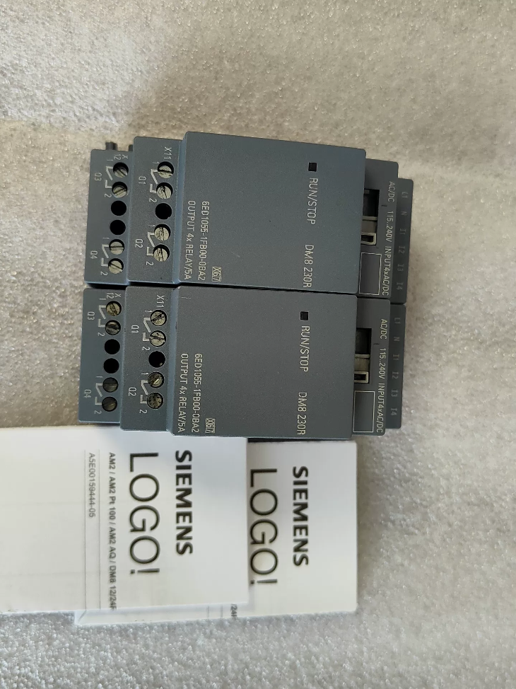

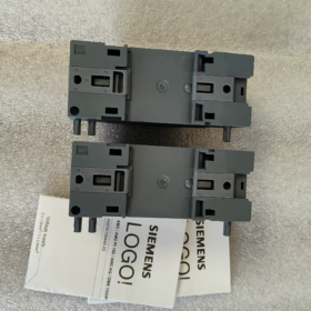
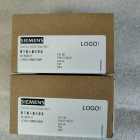
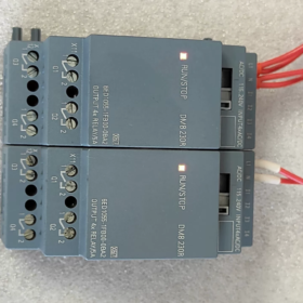
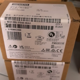
Nom et prénom: LOGO! DM8 230R Digital I/O Module d'extension (LOGO! 8 Série)
- Interprétation du code modèle
6ED1055-1FB00-0BA2
6ED1055: Prefix for LOGO! 8 modules d'extension en série
1Facebook: DM8 230R, 115/230 Alimentation CA/CC, 4DI/4DO relay output
00: Version du matériel
0BA2: Version du micrologiciel (LOGO!8 platform, incompatible with LOGO!6/7 (0BA6/0BA7) main units)
- Spécifications électriques de base
| Article | Spécification |
| Alimentation | 115~230 V AC/DC (85~265 V AC; 100~253 V DC) |
| Entrée numérique DI | 4 chaînes, universal AC/DC signal |
| Logique 0: <40 V AC /<30 V DC | |
| Logique 1: >79 V AC />79 V DC | |
| Input delay: 0→1=40 ms; 1→0=75 ms | |
| Sortie numérique DO | 4 channels relay normally-open isolated contacts |
| Charge résistive: 5 UN / 250 V et | |
| Charge inductive: 3 UN / 250 V et | |
| Minimum load current: 100 mA | |
| Fréquence de commutation maximale: 2 Hz (résistif); 0.5 Hz (inductif) | |
| Montage | 35 mm rail DIN, largeur 2 LE (35.5 mm) |
| Dimensions hors tout | W35.5 × H90 × D58 mm |
| Classe de protection | IP20 (pour installation en armoire uniquement) |
| Température ambiante de fonctionnement | -20 ℃ ~ +55 ℃, pas de condensation |
| Poids | Environ. 0.17 kilos |
- Compatibility Instructions
✅ Supported Main Units: LOGO! 8 / 8.2 / 8.3 (0Micrologiciel BA8 et versions ultérieures)
Modèles d'unités principales typiques: 6ED1052-1FB08-0BA0, 6ED1052-1FB08-0BA1 and other 230 V unités principales
❌ Non pris en charge: LOGO! 6, LOGO!7 (0BA6/0BA7) main units. Le protocole du bus de fond de panier diffère, communication not available
- Définition du terminal (Haut: Pouvoir & Saisir; Bas: Sortir)
Bornes supérieures (Alimentation + Saisir)
L1, N: Alimentation de fonctionnement du module
I1, I2, I3, I4: 4 entrées numériques
Bornes inférieures (Sortie relais)
T1, T2, T3, T4: 4 groupes de contacts normalement ouverts à relais indépendants (2 terminaux par canal, pas de borne commune)
⚠️Important: Quatre relais sont électriquement isolés; différents circuits de tension peuvent être connectés à chaque canal indépendamment
- Scénarios d'application typiques
Petit contrôle CVC, pompe à eau & contrôle du ventilateur, circuits d'éclairage, verrouillage de porte, lignes de convoyage simples. Idéal pour les sites équipés de l'existant 220 Capteurs V AC et circuits de contacteurs sans alimentation DC supplémentaire.
- Lignes directrices de sélection & Pièges courants
- Le signal d’entrée doit dépasser 79 V pour être reconnu de manière fiable comme logique 1; les signaux basse tension ne peuvent pas être utilisés.
- Contacts mécaniques du relais non adaptés à la commutation haute fréquence. Select transistor output modules for frequent operation.
- Maximum expansion limit: A single LOGO! main unit can connect up to 4 modules d'extension.
- All input channels are recommended to use the same phase power. Do not connect I1~I4 across different phases to avoid false triggering caused by induced voltage.
- Install RC snubbers or freewheeling diodes in parallel with inductive loads (contacteurs, électrovannes) to extend relay service life.
- Comparison with Similar Series Models
6ED1055-1FB10-0BA2 (DM16 230R): 8DI+8DO relay version with doubled I/O capacity
6ED1055-1HB00-0BA2 (DM8 24R): 24 V DC powered version
Complete Technical Documentation for Siemens 6ED1055-1FB00-0BA2 (LOGO! DM8 230R)
- Informations de base sur le produit
Numéro de commande: 6ED1055-1FB00-0BA2
Nom du produit: LOGO! DM8 230R Digital Expansion Module (LOGO!8 Série)
Fonction: 4DEPUIS / 4DO relay output expansion module
Positionnement: Extend I/O capacity for LOGO!8/8.2/8.3 main units, cannot run standalone
- Full Model Code Interpretation
6ED1055 1FB00 0BA2
- 6ED1055: LOGO! 8 series expansion module category
- 1Facebook: DM8 230R, 115~230 V AC/DC power supply, 4-channel AC input, 4 independent normally-open relay outputs
- 00: Révision du matériel
- 0BA2: Version du micrologiciel (LOGO!8 platform, incompatible with LOGO!6/7 (0BA6/0BA7) contrôleurs)
- Detailed Electrical Specifications
3.1 Alimentation
| Paramètre | Spécification |
| Tension nominale | 115…230 V CA/CC |
| Plage de fonctionnement | CA: 85~265 V; CC: 100~253 V |
| Gamme de fréquences | 47~63 Hz |
| Consommation électrique des modules | Max.. 2.2 Virginie |
3.2 Entrée numérique DI (I1, I2, I3, I4)
Quantité: 4-channel universal AC/DC input
Logique 0: <40 V CA / <30 V CC
Logique 1: >79 V CA / >79 V CC
Délai de réponse d'entrée: 0→1: 40 MS; 1→0: 75 MS
Type d'entrée: Entrée de tension alternative passive, 24 V DC signals are not allowed
Longueur maximale du câble: 100 m (câble non blindé)
3.3 Sortie relais DO (T1 ~ T4, isolated normally-open contacts)
⚠️ Four relays are mutually isolated; différents circuits de tension peuvent être câblés à chaque canal
|Type de charge|Contacter l'évaluation|
| —| —|
|Charge résistive (Résistances, Éclairage)|5 UN / 250 V et|
|Charge inductive (Contacteurs, Électrovannes)|3 UN / 250 V et|
|Courant de transport minimum|100 mA (De mauvaises performances de contact peuvent survenir en dessous de cette valeur)|
|Fréquence de commutation maximale|Charge résistive: 2 Hz; Charge inductive: 0.5 Hz; Limite mécanique à vide:10 Hz|
|Opération interdite|La connexion parallèle de plusieurs contacts de sortie pour augmenter le courant est interdite|
- Mécanique & Paramètres environnementaux
Montage: 35 Rail DIN standard de mm
Largeur: 2 LE (35.5 mm)
Dimensions hors tout: W35.5 × H90 × D58 mm
Poids: Environ. 170 g
Classe de protection: IP20 (utilisation en armoire intérieure uniquement)
Température de fonctionnement: -20 ℃ ~ +55 ℃ (condensation interdite)
Stockage & Température de transport: -40 ℃ ~ +70 ℃
Humidité relative: 5% ~ 95%, pas de condensation
Résistance aux vibrations: Conforme à la CEI 60068-2-6
- Définition du terminal
Bornes supérieures (Alimentation + Saisir)
L1, N: Alimentation de fonctionnement du module 115~230 V AC/DC
I1, I2, I3, I4: 4 entrées numériques
Bornes inférieures (Sortie relais)
Q1 deux terminaux: 1st relay normally-open contact
Q2 deux terminaux: 2nd relay normally-open contact
Q3 deux terminaux: 3rd relay normally-open contact
Q4 deux terminaux: 4th relay normally-open contact
- Règles de compatibilité du système
✅ Supported Main Units (LOGO!8 Plate-forme)
6ED1052-1FB08-0BA0, 6ED1052-1FB08-0BA1, tous les logos!8.2 / 8.3 230 Contrôleurs V
Quantité d'expansion maximale: Jusqu'à 4 modules d'extension par LOGO! unité principale
❌ Équipements incompatibles
LOGO!6 (0BA6), LOGO!7 (0BA7) contrôleurs hérités. Incompatibilité du protocole de communication du fond de panier, ne peut pas être reconnu.
- Exigences de configuration logicielle
Logiciel de programmation: LOGO! Soft Confort V8.0 ou supérieur
- Sélectionnez le modèle de module d'extension correspondant dans le catalogue de matériel du projet;
- Les adresses d'E/S des modules d'extension suivent automatiquement les adresses de l'unité principale, aucune affectation manuelle requise;
- Vérifiez la liste du matériel avant le téléchargement du programme pour éviter les erreurs causées par une incompatibilité de version.
- Certifications
CE, UL, ASC, CQC; Conforme à la norme EN 61010-1, DANS 55011 (CEM classe B, applicable aux environnements de bâtiments commerciaux)
- Directives de mise en œuvre de l'ingénierie (Spécifications officielles)
- Les amortisseurs RC doivent être connectés en parallèle avec des charges inductives (électrovannes, bobines de contacteur) pour les circuits CA afin de prolonger la durée de vie du relais.
- Il est recommandé à tous les canaux d'entrée d'adopter une alimentation à partir de la même phase. Ne connectez pas les bornes d'entrée sur différentes phases pour éviter un faux déclenchement induit par une tension parasite..
- Les contacts des relais mécaniques ont une durée de vie limitée. Sélectionnez les modules de sortie à transistor (DM8 24T) pour les applications start-stop à haute fréquence.
- Le module doit être installé horizontalement; l'installation verticale inversée est interdite.
- Maintenez un espace de dissipation thermique dans les armoires de commande pour éviter l'accumulation de chaleur lorsque plusieurs modules sont montés côte à côte..
- Tableau de comparaison de modèles similaires
| Numéro de commande. | Modèle | Alimentation | Configuration des E/S | Type de sortie |
| 6ED1055-1FB00-0BA2 | DM8 230R | 115~230 V CA/CC | 4D/4C | Relais |
| 6ED1055-1FB10-0BA2 | DM16 230R | 115~230 V CA/CC | 8D/8C | Relais |
| 6ED1055-1HB00-0BA2 | DM8 24R | 24 À DC | 4D/4C | Relais |
Cas d'application d'ingénierie pour Siemens 6ED1055-1FB00-0BA2 (LOGO! DM8 230R)
Avantages principaux: Direct acquisition of 115~230 V AC/DC signals; isolated relay contacts directly drive 220 V loads without additional DC power supply. Assorti au logo! 230Unité principale RCE (6ED1052-1FB08-0BAx). Convient aux projets de nouvelle construction et de rénovation avec des circuits de commande entièrement CA sur site.
Allocation d'E/S: 4DEPUIS (220 Entrée V CA) + 4 independent normally-open relay outputs
Cas 1: Contrôle d'alternance automatique de pompe à eaux usées double pour puisard de sous-sol (Approvisionnement en eau du bâtiment & Drainage)
- Exigences du projet
Deux 220 V sewage pumps for underground parking sump; high/low level float switches with 220 Signaux de contact V.
Niveau d'eau élevé: Démarrer les pompes; niveau ultra élevé: Dual pumps run simultaneously + audible & alarme visuelle;
Niveau d'eau bas: Toutes les pompes s'arrêtent;
Alternance automatique de synchronisation entre les pompes principales et de secours pour une usure uniforme; Fonction de commutation manuelle/automatique et de retour d'erreur.
- Configuration matérielle
Unité principale: 6ED1052-1FB08-0BA1 (LOGO! 230RCE, à bord 8DI/4DO)
Module d'extension: 6ED1055-1FB00-0BA2 ×1 (DM8 230R)
- Affectation des E/S
Onboard Channels of Main Unit
I1: Commutateur automatique/manuel; I2: Pompe à démarrage manuel 1; I3: Pompe à démarrage manuel 2; I4: Arrêt d'urgence;
T1: Contacteur de pompe 1; T2: Contacteur de pompe 2;
Canaux d'extension du DM8 230R
I5 (Module I1): Interrupteur à flotteur de bas niveau; I6 (Module I2): Interrupteur à flotteur de haut niveau; I7 (Module I3): Interrupteur à flotteur de niveau ultra élevé; I8 (Module I4): De rechange;
Q5 (Module Q1): Buzzer d'alarme de niveau ultra élevé; Q6 (Module Q2): Témoin de défaut; Q7, Q8: De rechange
- Points forts de la solution
Les interrupteurs à flotteur se connectent directement au module 220 Entrées V sans relais intermédiaires. Quatre contacts de relais isolés peuvent piloter les alarmes et les voyants séparément avec des circuits d'alimentation indépendants. Aucune alimentation DC24V supplémentaire requise à l'intérieur de l'armoire de commande, simplification du câblage.
Cas 2: Air frais & Contrôle de verrouillage du ventilateur d'extraction pour immeuble de bureaux (CVC)
- Exigences du projet
Quatre 220 V ventilateurs d'air neuf/d'extraction avec fonctionnement programmé, liaison de température, retour de fonctionnement du ventilateur et alarme de défaut. E/S intégrées à l'unité principale insuffisantes, étendu par un module supplémentaire.
- Liste du matériel
LOGO! 230Unité principale RCE + 6ED1055-1FB00-0BA2 ×1
- Utilisation des modules
Canaux DI: 4-contacteur de canal exécutant des signaux de retour (220 V);
Canaux FAIRE: Control contactors for extra two exhaust fans, défaut audible & alarme visuelle, system running indicator light.
- Caractéristiques d'ingénierie
Tous les signaux de commande sont 220 V et; les contacts de relais isolés permettent une alimentation électrique à différentes phases. La largeur compacte 2TE permet d'économiser de l'espace sur le rail DIN pour les petites armoires de commande murales.
Cas 3: Timed Group Control of Plant Lighting (Système d'éclairage du bâtiment)
- Exigences
Plusieurs groupes de 220 Circuits d'éclairage V pour l'éclairage routier et périmétrique de l'usine; Commutation échelonnée basée sur le temps via une horloge interne en temps réel; Local manual pushbutton override; Retour d'information sur l'état des défauts.
- Configuration matérielle
LOGO! 230RCE (Horloge en temps réel intégrée) + DM8 230R (6ED1055-1FB00-0BA2)
- Affectation des E/S du module
DEPUIS: 4-channel local manual pushbuttons (220 Signal V);
FAIRE: Drive AC contactor coils for 4 groupes d'éclairage.
- Raison de la sélection
Module relay supports maximum 5 Une charge résistive, capable of directly driving small contactors. Lighting circuits are electrically isolated; single circuit failure will not affect others.
Cas 4: Commutateur de transfert automatique simple pour double alimentation d'une petite station de pompage
- Exigences du processus
Deux 220 V contrôler les sources d'alimentation (principal + attendre). Passage automatique en mode veille en cas de panne de courant principale; interlock to prevent parallel operation; status indication and fault alarm available.
- Configuration matérielle
LOGO! 230Unité principale RC + 6ED1055-1FB00-0BA2
- Affectation des E/S
Extension DI: Signaux de retour de détection de tension d'alimentation double;
Extension DO: Commande des bobines de fermeture de deux disjoncteurs et indicateur de fin de commutation.
Cette configuration est largement adoptée dans les projets de rénovation de distribution d'énergie et répertoriée comme application typique officielle par Siemens..
Cas 5: Greenhouse Evaporative Cooling Fan & Spray Solenoid Valve Interlock Control (Automatisation agricole)
Exigences
Activer automatiquement les ventilateurs de refroidissement et les électrovannes de pulvérisation lorsque la température & humidity exceed threshold; retarder l'arrêt; boutons manuels locaux et retour d'informations sur les défauts de l'équipement.
Matériel
LOGO! 230RCE + DM8 230R
Extension DI: Boutons poussoirs manuels, retour défaut relais thermique ventilateurs;
Extension DO: 220 Électrovanne de pulvérisation en V, contacteur de ventilateur de secours.
Avis
Les électrovannes appartiennent aux charges inductives. Installez des amortisseurs AC RC en parallèle avec les sorties relais pour prolonger la durée de vie du relais..
Cas 6: Barrière de sécurité, Verrouillage du convoyeur et des voyants d'avertissement pour les équipements de transport légers (Machines OEM)
Logique de contrôle
Le convoyeur est autorisé à démarrer uniquement lorsque la barrière de sécurité est fermée; le convoyeur s'arrête immédiatement une fois la porte ouverte; le voyant d'avertissement reste allumé et le buzzer retentit par intermittence pendant le fonctionnement; l'arrêt d'urgence a la plus haute priorité.
Configuration matérielle
LOGO! Capacité d'E/S de l'unité principale insuffisante, étendu via 6ED1055-1FB00-0BA2:
DEPUIS: Fin de course de porte de sécurité, arrêt d'urgence, bouton de réinitialisation;
FAIRE: Contacteur de convoyeur, audible & alarme visuelle.
Spécifications générales obligatoires d’ingénierie pour tous les cas
- ✅ Règle de câblage d'entrée: Tous 4 Les voies DI doivent être alimentées par la même phase L + N. Ne câblez pas I1 ~ I4 entre différentes phases sous tension pour éviter un faux déclenchement causé par une tension induite..
- ✅ Les sorties relais sont des contacts isolés normalement ouverts.; différents circuits de tension peuvent être câblés à chaque canal.
- ✅ Les composants Snubber sont obligatoires pour les charges inductives (contacteurs, électrovannes).
- ✅ Maximale 4 les modules d'extension peuvent être mis en cascade avec un seul LOGO! unité principale.
- ✅ Uniquement compatible avec LOGO!8 / 8.2 / 8.3 main units (0Micrologiciel BA8). LOGO!7 et les versions antérieures ne sont pas prises en charge.
- ✅ Ne peut pas fonctionner de manière indépendante; doivent être empilés sur le côté droit du LOGO! unité principale via bus d'extension.





NH42-63-318x560.png "Commutateurs de transfert automatiques de type PC CHINT (ATS)NH42-63/4SZ")



