 Contacteur,disjoncteur,capteur,Encodeur,API,Convertisseur

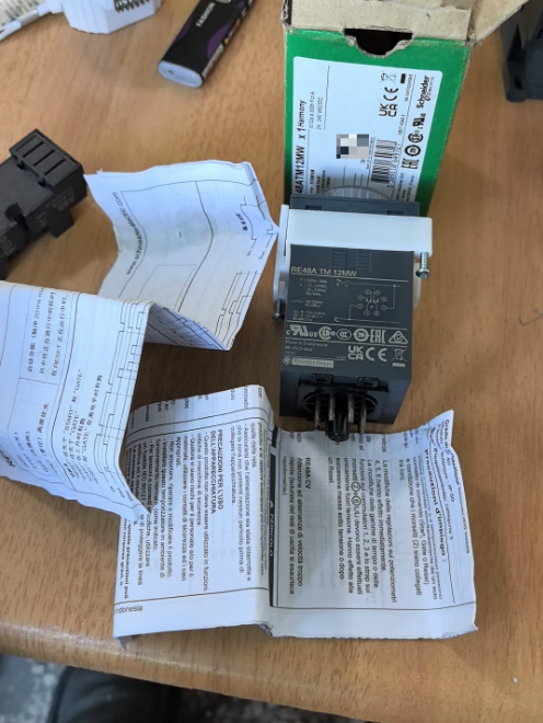

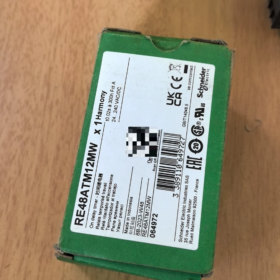
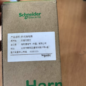
Schneider Manuel d'installation du relais temporisé RE48ATM12MW
Nom complet du produit: Relais temporisé électronique Harmony série RE48A
Modèle: RE48ATM12MW (8-épingle, 2 contacts inverseurs, 24~240 V CA/CC, Délai de mise en marche uniquement)
Note: Ce manuel est compilé sur la base de la fiche technique officielle de Schneider, disponible pour une installation sur site, mise en service et archivage des documents.
Table des matières
RE48ATM12MW
RE48A: Série Harmonie RE48A, 48Electronique à montage sur panneau ×48 mm relais temporisé
T: Délai de mise en marche (fonction unique, délai de mise sous tension uniquement)
M.: Large tension d'alimentation 24…240 V AC/DC
12: 2 contacts inverseurs (2CO)
W: 8-interface de prise enfichable à broches
Définition de base: Relais temporisé à fonction unique. Il ne peut pas être commuté sur un délai de déclenchement, modes impulsion ou clignotant.
- Principales spécifications électriques
| Article | Spécification |
| Mode Fonction | Délai de mise en marche (Mode A) |
| Tension d'alimentation | 24~240 V CA/CC Universel (CA & Compatible CC) |
| Sortie contact | 2 jeux de contacts inverseurs (2CO, DPDT), AgNi cadmium-free contacts |
| Rated Contact Current | 5UN / 250V et (AC-12); 1.5A AC-15; 2A/30V DC-13 |
| Adjustable Delay Range | 0.02s ~ 300h, selectable front panel ranges: |
| 0.02–1.2s / 0.05-3s / 0.2–12s / 0.5–30s / 2–120s / 5–300s | |
| 0.2–12min / 0.5–30min / 2–120min /5–300min | |
| 0.2–12h / 0.5–30h / 2–120h /5–300h | |
| Précision de répétition | ±0.2% of full scale |
| Consommation d'énergie | 0.5W(24V) ~ 1.7W(240V) |
| Endurance mécanique | 30 millions d'opérations; Endurance électrique (5Une charge résistive): 100,000 opérations |
| Protection contre la pénétration | Front face IP50, housing IP40 |
| Découpe du panneau | Standard 48×48mm instrument cutout |
| Interface | 8-pin circular socket |
| Poids net | Environ. 140g |
- Logique de fonctionnement (Délai de mise en marche)
- Power applied to A1/A2 → timing starts;
- Before timing elapses: contacts remain in initial state;
- When preset delay expires: both sets of changeover contacts operate simultaneously;
⚠️Important: Front panel DIP selector
Position 1: Both outputs timed
Position 2: One timed output, the other instantaneous upon power-up
- Power removal resets the relay; timing restarts after re-energization.
- Matching Sockets & Accessoires
La prise n'est PAS fournie avec le relais et doit être commandée séparément:
- Prise de montage sur rail DIN: RUZC2M (8-borne à vis à broches, le plus courant)
- Prise de montage PCB: RE48ASOC8VENDU
Accessoires en option:
RE48ASETCOV: Mise en place du capot de protection (empêche tout réglage non autorisé)
RE48AIPCOV: Poussière IP64 & couverture avant imperméable
- 8-Définition de la borne à broches (Prise RUZC2M)
2, 7: A1, Bornes d'alimentation de la bobine A2
1-3-4: 11er jeu de contacts inverseurs
8-5-6: 2et jeu de contacts inverseurs
- Procédure de configuration
- Basculer le sélecteur de base de temps du panneau avant (s/min/h)
- Sélectionner la limite de plage via le bouton rotatif (par exemple. 30gamme)
- Tournez le bouton pointeur pour définir le délai cible
- Sélectionner le mode de fonctionnement: Sorties à double temporisation / Un chronométré + une sortie instantanée
- Modèles de remplacement alternatifs
Remplacement direct
- RE48AMH13MW (8-épingle, version multifonction). Prend en charge le délai, synchronisation des impulsions et plus encore. Entièrement interchangeable avec la même prise.
Différence: ATM = délai de démarrage uniquement; AMH = Multifonction
Alternative compacte (Type de rail DIN intégré, pas de prise séparée)
RE22R2AMU (Montage sur rail DIN, taille plus petite, ne convient pas à l'installation d'une découpe de panneau 48 × 48)
- Scénarios d'application typiques
Ventilateur & retard de démarrage de la pompe, retard de démarrage du moteur étoile-triangle
Démarrage séquentiel des systèmes de convoyage, délai de mise sous tension de l'équipement
Contrôle de synchronisation du système CVC, allumage retardé de l'éclairage
- Risques & Interdictions
- Ne pas alimenter une tension supérieure à 250 V dans les circuits de contact; diode de roue libre recommandée pour les charges inductives DC;
- Brève coupure de courant <10ms ne déclenchera PAS la réinitialisation; une durée de mise hors tension suffisante est requise pour une réinitialisation fiable;
- Ce modèle n'a pas de borne de réinitialisation externe. La réinitialisation ne peut être obtenue qu'en coupant l'alimentation électrique;
- Évitez les environnements avec une condensation continue. Ajoutez un filtrage si installé à proximité des onduleurs pour la suppression CEM.
- Consignes de sécurité (Lecture obligatoire)
- Présentation du produit & Description du modèle
- Matching Sockets & Sélection d'accessoires
- Deux méthodes d'installation & Procédures
- Définition du terminal & Schéma de câblage standard
- Procédure de paramétrage
- Étapes de mise en service à la mise sous tension
- Spécifications électriques
- Guide de dépannage
- Restrictions d'installation & Exigences environnementales
- Consignes de sécurité ⚠️【Important】
- Couper l'alimentation électrique en amont avant toute installation, opérations de câblage et de démontage. Le travail sous tension est interdit;
- Les circuits de contact ne doivent pas dépasser la charge nominale: 5A/250 V CA. La diode de roue libre est recommandée pour les charges inductives CC;
- Ne pas déployer dans des environnements inflammables/explosifs, endroits avec condensation continue ou gaz corrosif;
- Aucune pièce réparable à l’intérieur de l’unité. Ne pas démonter; remplacer l'unité complète en cas de panne;
- Vérifier la tension d'alimentation avant l'installation: 24~240 V CA/CC. Tension >264V est interdit;
- Couple de serrage des bornes femelles: 0.8~1,2 N·m. Évitez de trop serrer car cela fissurerait la base en plastique..
- Présentation du produit
Fonction: Retard à la mise en route à fonction unique (Délai de mise sous tension)
Facteur de forme: 48Montage sur panneau ×48 mm, 8-interface enfichable à broches
Alimentation: Large plage 24…240 V CA/CC
Sortir: 2 jeux de contacts inverseurs (2CO)
Plage de retard: 0.02s ~ 300h, base de temps sélectionnable via le commutateur du panneau avant
Indice de protection: Façade IP50, housing IP40
Récapitulatif du code de modèle
RE48A-T-M-12-W
RE48A: 48Relais temporisé panneau ×48
T: Délai de mise en marche (fonction unique)
M.: 24Alimentation en tension large ~ 240 V AC/DC
12: 2 contacts inverseurs
W: 8-prise circulaire à broches
- Prise correspondante & Accessoires en option
La prise n'est pas incluse avec RE48ATM12MW et doit être commandée séparément
| Nom | Modèle | Application |
| Prise pour montage sur rail DIN | RUZC2M (8-épingle) | Montage sur rail DIN dans une armoire de commande (le plus largement utilisé pour les projets) |
| Prise à souder PCB | RE48ASOC8VENDU | Installation de soudure de PCB |
| Couvercle de verrouillage des paramètres | RE48ASETCOV | Empêcher les ajustements horaires non autorisés sur site |
| Couverture avant étanche IP64 | RE48AIPCOV | Améliorer la poussière & résistance à l'eau pour les panneaux de commande |
- Deux procédures d'installation
Méthode 1: Montage sur rail DIN (Prise RUZC2M)
- Alignez les clips de la prise RUZC2M sur le rail DIN standard de 35 mm, appuyez jusqu'à ce qu'il soit complètement verrouillé;
- Desserrez les vis des bornes à douille avec un tournevis pour le câblage;
- Terminez tout le câblage des câbles;
- Alignez verticalement le RE48ATM12MW avec une prise à 8 broches, appuyez uniformément jusqu'à ce qu'il soit complètement en place;
Ne forcez pas l'insertion en biais pour éviter la flexion des broches de contact..
Méthode 2: Montage sur découpe du panneau de l'armoire de commande
- Dimension de découpe du panneau: 48⁺⁰·⁶₋₀ mm × 48⁺⁰·⁶₋₀ mm
- Épaisseur de panneau applicable: 1mm~10 mm
- Insérez le corps du relais depuis l'avant du panneau à travers la découpe;
- Monter le support de montage à l'arrière du panneau, serrer les vis de fixation uniformément des deux côtés;
- Connectez la prise de câblage à 8 broches par l'arrière;
Réservez un dégagement ≥ 10 mm entre les appareils adjacents pour la dissipation thermique.
- 8-Définition de la borne à broches (Prise standard RUZC2M)
| Numéro de borne. | Description de la fonction |
| 2 | Borne d'alimentation A1 |
| 7 | Borne d'alimentation A2 |
| 1 | Commun du 1er jeu de contacts COM1 |
| 3 | Temporisé Normalement Ouvert NO1 (1premier ensemble) |
| 4 | Temporisé Normalement Fermé NC1 (1premier ensemble) |
| 8 | Commun du 2ème jeu de contacts COM2 |
| 6 | Temporisé Normalement Ouvert NO2 (2et ensemble) |
| 5 | Temporisé Normalement Fermé NC2 (2et ensemble) |
Sélecteur de fonction du panneau avant
Position 1: Both outputs timed (Valeur par défaut d'usine)
Position 2: One timed output, une sortie instantanée à la mise sous tension
Guide de câblage standard
- Circuit de puissance: Alimentation de commande connectée à 2,7 (A1/A2)
Alimentation CA: L et N peuvent être connectés à 2/7 arbitrairement, pas de polarité
Alimentation CC: Polarité positive/négative interchangeable, universel pour AC & CC
- Circuit de charge:
Borne commune 1 → Temporisé NON 3; Borne commune 8 → Temporisé NON 6
Logique de fonctionnement: Puissance appliquée à 2,7 → le chronométrage commence; Après un délai prédéfini, 1-3 fermé, 8-6 fermé. Le relais se réinitialise immédiatement après une coupure de courant.
- Étapes de configuration des paramètres du panneau avant
- Alimenter le relais (Voyants LED UP = état de synchronisation en veille);
- Sélecteur de base de temps: Choisissez s / min / h (Secondes / Minutes / Heures);
- Tournez le bouton de réglage pour définir la durée du retard cible;
- Basculer le sélecteur de fonction: Sorties à double temporisation / Un chronométré + une sortie instantanée;
- Installez éventuellement le capot de protection RE48ASETCOV pour verrouiller les paramètres.
Plages de retard disponibles
0.02–1.2s / 0.05-3s / 0.2–12s / 0.5–30s
2–120s / 5–300s / 0.2–12min / 0.5–30min
2–120 min /5 à 300 min /0,2 à 12 h /0,5 à 30 h /2 à 120 h /5 à 300 h
- Procédure de mise en service à la mise sous tension
- Vérifiez le câblage dans des conditions de mise hors tension; confirmer l'absence de court-circuit dans les circuits d'alimentation et de charge;
- Mettre sous tension; LED UP fixe = état de veille de synchronisation;
- Attendez que le délai prédéfini expire;
- En cas de retard: État du commutateur des contacts;
- Couper l'alimentation des bornes 2,7 pour la réinitialisation du relais; le timing redémarre après la remise sous tension;
- Effectuer plusieurs tests de cycle pour vérifier la précision du timing;
Brève coupure de courant <10ms ne peut pas réinitialiser le relais. Coupure de courant complète ≥ 50 ms requise pour une réinitialisation fiable.
- Spécifications électriques de base
| Article | Paramètre |
| Gamme d'approvisionnement | 24~240 V CA/CC, 50/60Hz |
| Contacter l'évaluation | 5Un 250V AC-12; 1.5A AC-15; 2A/30V DC-13 |
| Précision de répétition du timing | ±0,2 % pleine échelle |
| Consommation d'énergie | 0.5W~1,7W |
| Endurance mécanique | 30 millions d'opérations; Endurance électrique 100,000 opérations sous charge résistive |
| Température ambiante de fonctionnement | -20 ℃ ~ +55 ℃, pas de condensation |
| Température de stockage | -40 ℃ ~ +70 ℃ |
- Tableau de dépannage
| Phénomène de défaut | Causes possibles | Solutions |
| La LED UP ne s'allume pas après la mise sous tension | 1. Pas de courant 2/7; 2. Tension hors plage; 3. Mauvais contact des broches | Vérifier la tension d'alimentation, réinstaller l'unité de relais, mesurer la tension aux bornes de la prise 2 & 7 |
| Les contacts s'activent immédiatement après la mise sous tension, sans délai | Réglage incorrect du commutateur DIP; Confusion des modèles (Ne pas confondre avec le RE48AMH multifonction) | Vérifier la position du sélecteur; Confirmer que le modèle est RE48ATM12MW (Délai de mise en marche uniquement) |
| Les contacts ne parviennent pas à changer après l'expiration du délai | Charge surchargée; Érosion des contacts; Câblage lâche | Réduire le courant de charge, serrer les bornes; Remplacer le relais si les contacts sont endommagés |
| Durée de synchronisation inexacte | Plage de base de temps incorrecte; Température ambiante excessive | Resélectionner la bonne base de temps; Améliorer la dissipation thermique |
| Réinitialisation fréquente involontaire | Chute de tension transitoire ou interférence sur l'alimentation électrique | Ajoutez des composants de filtrage pour stabiliser l'alimentation du circuit de commande |
- Restrictions d'installation & Limites opérationnelles
❌ Opérations interdites:
- Appliquer une tension supérieure à 250 V aux circuits de contact;
- Montage à proximité des onduleurs et des grands contacteurs (forte interférence électromagnétique);
- Installation fermée provoquant une accumulation de chaleur; fonctionnement continu ci-dessus 55 ℃ température ambiante;
- Tirez sur les câbles pour débrancher de force le relais, ce qui entraîne des broches de douille pliées;
- Déployer pour le contrôle des impulsions haute fréquence (accélère le vieillissement des composants électroniques).
✅ Recommandations:
Installer des composants d'absorption des surtensions en parallèle pour les charges inductives (bobines de contacteur); Réserver un espace de ventilation à l'intérieur de l'armoire de commande; Utilisez des câbles en cuivre de 0,75 ~ 1,5 mm².
Appendice: Référence alternative
Remplacement compatible direct avec la prise: RE48AMH13MW (8-modèle multifonction à broches)
Différence: ATM = délai de démarrage uniquement; AMH prend en charge le délai, retard de déclenchement, clignotant et autres modes.



NH42-63-318x560.png "Commutateurs de transfert automatiques de type PC CHINT (ATS)NH42-63/4SZ")



