 Contattore,interruttore automatico,sensore,Codificatore,PLC,Convertitore

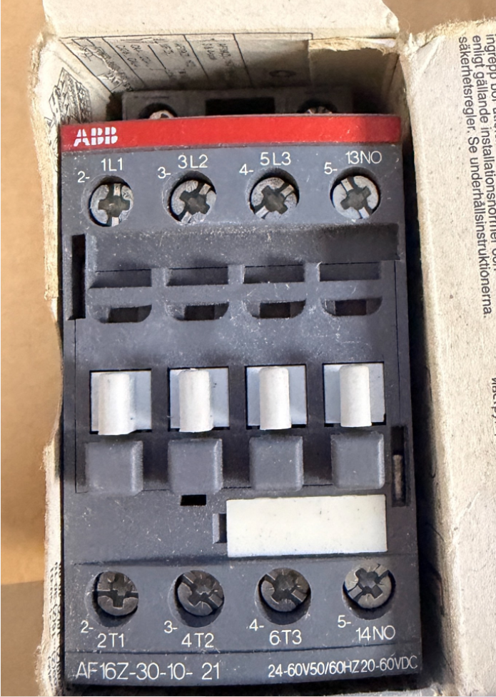

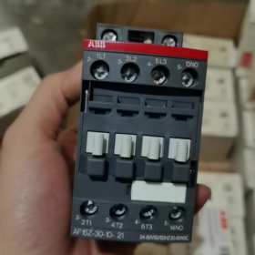
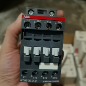
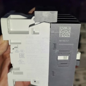
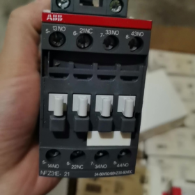
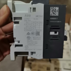
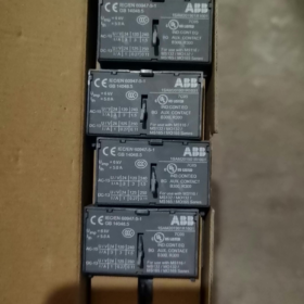
Original Factory Order No.: 1SBL176001R2110
- Definizione di scomposizione del modello
AF16Z 30 10 21
- AF16Z: Serie AF; Z = Low-power electronic wide-range coil (direct PLC drive capable); Dimensioni del telaio 16 classe
- 30: Contatti principali: 3 Normalmente aperto (3NO), no main Normally Closed contacts
- 10: Contatti ausiliari incorporati: 1 Normalmente aperto (1NO), 0 Normalmente chiuso
- 21: Coil code → Control voltage: 24~60 V AC 50/60Hz / 20~60 V DC
⚠️ Difference between AF…Z and standard AF: Extremely low coil power consumption, supports direct driving by DC24V PLC outputs, resistant to voltage dips (compliant with SEMI F47).
- Core Electrical Ratings
Maximum main circuit voltage: 690 V e
AC-1 (carico resistivo), ≤40°C ambient: 30 UN
AC-3 (3-motore di fase, 400 V): 18 UN, adatto per 7.5 motore da kW
AC-3 (690 V): 10.5 UN, massimo. 9 kW
Montaggio: Montaggio su guida DIN, collegamento con terminale a vite
Dimensioni complessive: W 45 mm × H 86 mm×D 77 mm
Temperatura operativa: -40~+70 °C (without thermal overload relay); -25~+60 °C (with thermal overload relay)
- Key Coil Characteristics
Wide-range AC/DC universal: AC 24~60 V / DC 20~60 V
Soppressione delle sovratensioni incorporata; no external RC snubber or diode required
Basso consumo energetico di mantenimento, ideal for continuous energized operation
Withstands short-term voltage fluctuations and voltage drops
- Identificazione del terminale
Circuito principale: 1L1-2T1, 3L2-4T2, 5L3-6T3
Contatto ausiliario: 14NO (Normalmente aperto)
- Common Alternatives & Distinctions
- AF16Z-30-10-11: Same voltage range, equipped with standard AF coil (non low-power Z coil); cannot be directly driven by low-current PLC outputs, non intercambiabile.
- AX16-30-10: AX economy series, without electronic wide-range coil, fixed control voltage; cannot replace AF16Z.
- For 1NO + 1Contatti ausiliari NC: Select model AF16Z-30-11-21.
- Applicazioni tipiche
Upstream of variable frequency drives, tifosi & pompe dell'acqua, HVAC equipment, semiconductor machinery, PLC DC output direct load control, industrial sites requiring high tolerance to voltage fluctuations.
ABB AF16Z-30-10-21 Contattore Installation Technical Document
Ordine n.: 1SBL176001R2110
- General Safety Instructions
⚠️ All installation, wiring and maintenance work must be carried out with all power disconnected; lockout-tagout procedure is mandatory. Work shall only be performed by qualified electricians.
- Classe di protezione: IP20. Solo per installazione in armadio. Do not install in open air, ambienti umidi, locations with heavy dust or corrosive gas exposure.
- Norme applicabili: CEI/EN 60947-1, CEI/EN 60947-4-1; UL/CSA certified.
- AF16Z is equipped with a low-power electronic wide-range coil with integrated surge suppression circuit. No external RC snubber or diode connection is required.
- Informazioni di base sul prodotto
2.1 Definizione del modello
AF16Z: Serie AF, dimensione del telaio 16, Z = low-power electronic coil
30: 3 contatti principali normalmente aperti
10: Integrato 1 contatto ausiliario normalmente aperto
21: Coil voltage range AC 24~60 V 50/60Hz / DC 20~60 V
2.2 Dimensioni complessive
Larghezza 45 mm × Altezza 86 mm × Depth 77 mm
2.3 Rating Summary Table
| Articolo | Parametro |
| AC-1 resistive load (40 째C) | 30 UN |
| AC-3 motor load (400 V) | 18 UN, compatibile con 7.5 kW 3-phase motor |
| Tensione operativa massima | 690 V e |
| Temperatura operativa (senza relè termico) | -40 째C ~ +70 째C |
| Temperatura operativa (with thermal overload relay) | -25 째C ~ +60 째C |
- Specifiche di installazione meccanica
3.1 Metodi di montaggio
Two mounting options available:
- Montaggio su guida DIN (Raccomandato)
Rail standard: TS35 (35×7.5 mm / 35×15 mm)
Operazione: Hook the bottom latch onto the rail, press down until an audible click confirms locking. Per la rimozione, use a flat screwdriver to pry the bottom latch and lift upwards.
- Base Plate Screw Mounting
Fasten diagonally using 2 × M4 screws; refer to outline drawing for mounting hole spacing.
3.2 Orientamento di montaggio & Liquidazione
- Montaggio verticale (terminali superiori & metter il fondo a) preferito. 90° horizontal side mounting is permitted; upside-down installation is forbidden.
- Multiple units may be mounted side-by-side without current derating. Maintain ≥15 mm vertical clearance for ventilation; keep away from heat-generating components such as resistors and inverters.
- Avoid installation in high-vibration locations. Vibration acceleration >0.5g requires vibration damping measures.
- Specifiche del cablaggio elettrico
4.1 Terminal Marking Definition
Upper main circuit: L1, L2, L3 (Power Inlet)
Lower main circuit: T1, T2, T3 (Load Outlet)
Non-UL applications allow power feed from top or bottom; UL certified installations require power input from upper L terminals.
Coil terminals A1, A2: Control signal input (AC/DC non-polarized)
Contatto ausiliario 13-14: Built-in normally open contact (1NO)
4.2 Specifiche del cavo & Lunghezza di spelatura
Lunghezza di spelatura standard del cavo: 10 mm
Main circuit conductors: Solid/stranded copper cable 1~6 mm²; ferrules recommended for flexible cables
Controllare / auxiliary circuit conductors: 0.75~2,5 mm²
4.3 Coppia di serraggio (Obbligatorio)
Terminali del circuito principale: 1.5 N·m
Bobina A1/A2 & auxiliary contact terminals: 1.2 N·m
Insufficient torque causes terminal overheating; excessive torque leads to thread stripping.
Recommended tools: PZ2 Pozidriv screwdriver / 5.5 mm flat torque screwdriver.
- Critical Coil Application Notes (Core Feature of AF16Z)
- Intervallo di tensione: AC24~60 V / DC20~60 V, wide voltage compatibility, direct drive by PLC DC outputs.
- Very low coil holding power consumption, suitable for long-term energized operation; compliant with SEMI F47 voltage sag immunity requirements.
- A1 and A2 are non-polarized; polarity does not matter for DC24V control.
- Do not apply control voltage exceeding 60 V, otherwise the electronic coil module will be destroyed.
- Installazione di accessori opzionali
- Side-mounted auxiliary contacts (CA4 series)
Snap-fit onto left/right side slots without tools. Massimo 2 sets of side auxiliary contacts can be fitted to AF16.
- Interblocco meccanico
Install for reversing circuit configuration of two AF16Z contactors to prevent simultaneous closing and short circuit between forward and reverse phases.
- Thermal overload relay matching
Compatible with TA25DU series thermal relays, direct snap-fit mounting underneath the contactor.
- Commissioning Procedure After Power-On
- Under power-off condition: Visual inspection for correct wiring, no metallic debris, all terminals tightened to specified torque.
- Manually actuate contactor mechanism to confirm smooth operation without jamming.
- Test control circuit independently: Apply rated control voltage to A1/A2; contactor shall pull in reliably and drop out smoothly upon power removal.
- Verify synchronous switching of auxiliary contact 13-14 with contactor operation.
- Connect main circuit for no-load test run; check for abnormal noise and rapid terminal temperature rise.
- 30-minute loaded operation test; recheck terminal temperature to ensure temperature rise stays within allowable limits.
- Installation Faults & Pratiche vietate
❌ Forbidden operations:
Exposed loose strands on cable terminals
Tightening terminals while energized
Control voltage outside the 20~60 V range
Blocking ventilation channels above and below the contactor
Direct installation in environments with combustible dust or continuous condensation
Common Post-Installation Issues
- Contactor chattering/unstable pull-in: Verify control voltage is above minimum operating level; check voltage drop along control cables.
- Surriscaldamento del terminale: Stringere nuovamente i terminali alla coppia specificata; confirm conductor cross-section is adequate.
- Failure to pull in when driven by PLC: Confirm unit is AF16Z (bobina a bassa potenza); standard AF16 coil cannot be directly driven by PLC transistor outputs.
- Requisiti di manutenzione
- Periodic inspection of terminal temperature and abnormal noise.
- Avoid repeated switching above rated breaking capacity.
- Never operate the contactor with arc shield removed. Replace the complete unit when contacts suffer severe ablation.
Mechanical Life Parameters of ABB AF16Z-30-10-21
The AF16Z shares identical mechanical construction with standard AF16. Official technical data:
✅ Mechanical endurance: 10 million operating cycles (10×10⁶ operations)
Test conditions: Rated control voltage, commutazione a vuoto, standard ambient temperature.
Supporting Key Parameters
- Maximum mechanical operating frequency: 3,600 operazioni all'ora
Continuous high-frequency operation shall not exceed this limit to avoid accelerated mechanical wear.
- Reference electrical endurance (depends on load type, not equal to mechanical life)
AC-3 (400 V motor load): ca. 1,000,000 cicli
AC-1 (carico resistivo): ca. 1,600,000 cicli
⚠️ Mechanical endurance represents the mechanical operating limit; service life in practical applications is normally determined by electrical erosion of contacts.
Osservazioni supplementari
- AF16Z only differs by its low-power electronic wide-range coil variant. Armature, linkage and contact mechanical structure are identical to standard AF16; mechanical endurance ratings remain unchanged.
- Actual mechanical endurance will decrease under harsh environments (polvere pesante, vibrazione continua, alta temperatura).
- Definition of mechanical endurance: Operating cycles of contactor pull-in/drop-out driven by coil only, with no load connected to main circuit.










NH42-63-318x560.png "Commutatori automatici di tipo PC CHINT (ATS)NH42-63/4SZ")



