 Contattore,interruttore automatico,sensore,Codificatore,PLC,Convertitore

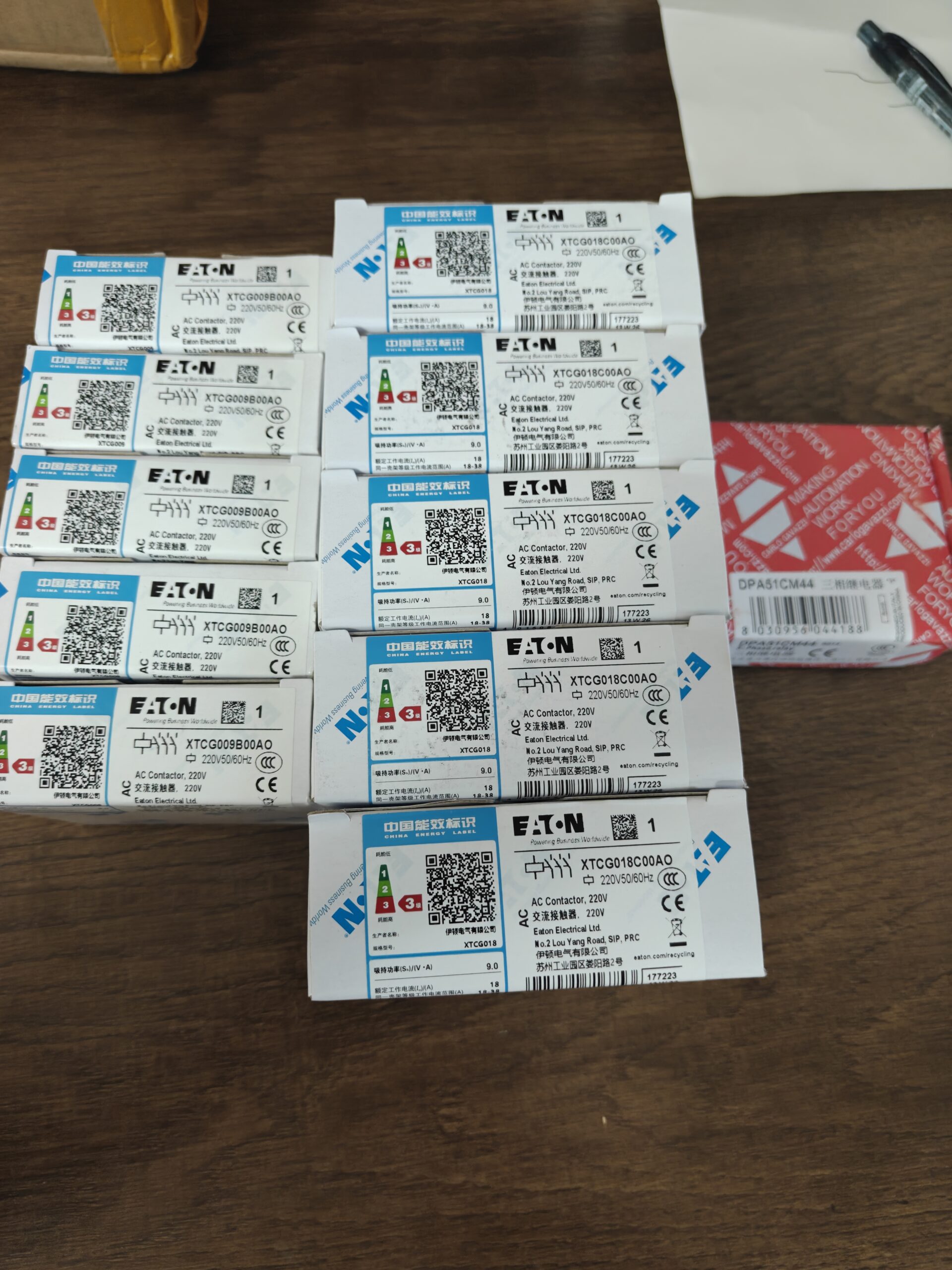

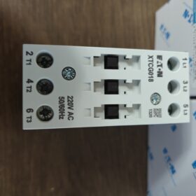
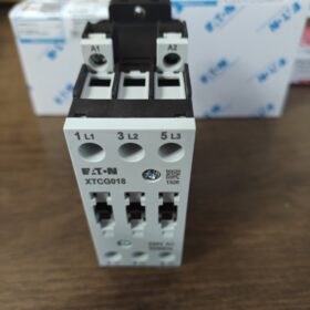
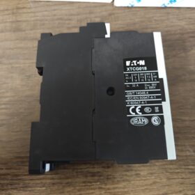
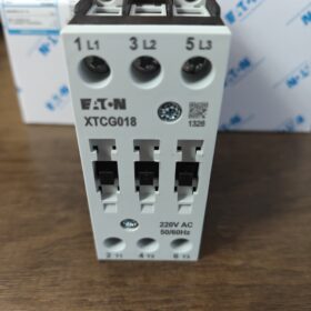
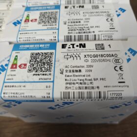
Nota: L'ultimo carattere è la lettera O, non cifra 0; appartiene alla sottoserie XTCG della gamma Eaton XT IEC contattori.
Decodifica del codice modello
| Segmento di codice | Descrizione |
| XT | Eaton Serie di controlli IEC della gamma XT |
| C | Contattore |
| G | Serie XTCG, Contattore motore tripolare con terminazione a vite |
| 18 | Corrente operativa nominale AC‑3:18A per il circuito principale |
| C | Taglia telaio C, 45 alloggiamento larghezza mm |
| 0 | Nessun contatto ausiliario integrato (0NO+0NC) |
| AL | Bobina: AC220V 50/60Hz (LA=AC, O=codice per bobina 220VAC) |
Definizione completa: 3-palo, AC-3 18A, nessun contatto ausiliario incorporato, Bobina AC220V, contattore CA con terminale a vite.
Parametri elettrici principali
| Articolo | Specifica |
| Poli principali | 3P‑NO (tre contatti principali normalmente aperti) |
| Corrente operativa nominale AC‑3 | 18Un carico motore a @400V |
| Carico resistivo AC‑1 | 32UN |
| Tensione di isolamento nominale Ui | 690V |
| Tensione della bobina | AC220V 50/60Hz |
| Contatti ausiliari | Nessuno a bordo; accessori esterni XTCGXF*** richiesti |
| Resistenza meccanica | ≥10000000 operazioni |
| Autonomia elettrica AC‑3 | ≥1000000 operazioni |
| Montaggio | Montaggio su guida DIN35 o montaggio su piastra posteriore avvitata |
| Terminali | Morsetti con morsetto a vite |
| Certificazioni | CCC, CE, UL, CSA, IEC60947‑4‑1 |
Fisico & Condizioni ambientali
Larghezza alloggiamento: 45 mm
Temperatura operativa:-25℃ ~ +60 ℃, vietata la formazione di condensa e ghiaccio
Temperatura di conservazione:-40℃ ~ +85 ℃
Peso: ca. 0.21 kg
Scenari applicativi tipici
- Controllo avvio-arresto motore trifase (Motore ≤7,5 kW a 400 V)
- Tifosi, pompe dell'acqua, trasportatori, compressori d'aria, macchine per l'imballaggio
- HVAC & assemblaggio OEM dell'armadio; può essere abbinato al relè di sovraccarico termico XTOD per la protezione da sovraccarico del motore
Elenco degli accessori compatibili
Blocco contatti ausiliari: XTCGXFAC (1NO+1NC ecc.), montato lateralmente
Relè termico: XTOD018 (0.1-18Una copertura di protezione del motore)
Modulo di interblocco meccanico: XTCG-MV, per l'inversione del circuito
Soppressore di sovratensioni: RC / modulo varistore per lato bobina
Modelli di sostituzione diretta & Note di sostituzione
- Alternativa della stessa serie: XTCG018C00DT (codice bobina diverso; verificare la tensione della bobina, non una sostituzione immediata)
- Alternativa tra serie: XTCE018C00A0 (Serie Eaton XTCE, funzionalmente equivalenti; verificare la compatibilità degli accessori)
⚠️Promemoria sulle trappole: XTCG018C00AO non ha contatti ausiliari integrati. Se sono richiesti segnali di feedback del PLC, è necessario montare un accessorio di contatto ausiliario esterno, altrimenti i circuiti di controllo non possono funzionare.
Condizioni operative non applicabili
Frequenza di commutazione>1200 cicli/ora
Gas pesante e corrosivo / ambiente molto polveroso senza un'adeguata protezione
Applicazioni con bobina CC (questa unità è del tipo con bobina CA)
Brevi istruzioni di cablaggio
- Circuito principale: Lato mandata L1-L2-L3; Carico T1-T2-T3 (motore) lato
- I terminali della bobina A1/A2 si collegano a AC220V
- Nessun contatto ausiliario integrato; tutti i segnali di feedback logico devono essere ottenuti da accessori con contatti ausiliari montati esternamente.
XTCG018C00AO (Telaio C) Montaggio & Dimensioni complessive (Unità: mm)
Tutti i modelli di telaio XTCG-C (009-032UN) condividono le stesse dimensioni dell'alloggiamento. Supporta il montaggio su guida DIN35 E il montaggio su piastra posteriore avvitata.
Dimensioni complessive (senza accessori montati)
| Articolo | Valore | Osservazioni |
| Larghezza L | 45 | Riferimento per la spaziatura della disposizione dell'armadio |
| Altezza H | 85 | Altezza totale compresa la parte superiore & terminali inferiori |
| Profondità D | 97.4 | Profondità all'interno del pannello dell'armadio dopo il montaggio su guida |
Dimensione complessiva: 45(W) × 85(H) × 97.4(D) mm
Dimensioni del ritaglio della piastra posteriore avvitabile (Guida DIN dimenticata, fissaggio diretto con vite sulla piastra posteriore del mobile)
Spaziatura da centro a centro dei fori di montaggio orizzontali: 35 mm
Spaziatura da centro a centro dei fori di montaggio verticali: 76 mm
Diametro del foro di fissaggio: Φ4.5 (Viti M4)
Margine dal foro al bordo: parte superiore di circa 4,5 mm & metter il fondo a.
Informazioni sull'installazione della guida DIN
- Guida DIN-35-7.5 standard (binario elettrico universale da 35 mm)
- Clip a scatto sul lato posteriore per il montaggio diretto su guida; montaggio senza attrezzi & smontaggio.
⚠️Cambio dimensione dopo l'installazione dell'accessorio
- Blocco contatti ausiliari a montaggio laterale XTCGXF: la larghezza aumenta di 10 mm, larghezza totale 55 mm
- Relè di sovraccarico termico a montaggio inferiore XTOD: l'altezza complessiva aumenta di circa 42,5 mm
- Interblocco meccanico XTCG-MV: due contattori affiancati senza gap zero; larghezza totale = somma diretta (45+45=90 mm)
Condizioni al contorno dell'installazione
- Spazio di raffreddamento: ≥10mm superiore & metter il fondo a; nessuno spazio obbligatorio da un lato all'altro (è possibile montare più unità adiacenti l'una all'altra)
- Non montare saldamente contro le partizioni chiuse dell'armadio; temperatura ambiente-25℃~+60℃, vietata la formazione di condensa.
- Dimensione massima consentita del conduttore: circuito principale 6mm²; circuito bobina 2,5 mm².
Riferimento a modelli incrociati
Modelli XTCG009C / XTCG025C / XTCG032C condivide l'alloggiamento identico, dimensioni del ritaglio e del montaggio su guida; differisce solo la corrente nominale del contatto interno. Codici di tensione della bobina vari (AO/DT ecc.) non producono alcun cambiamento nelle dimensioni fisiche.
Differenziazione della tensione operativa per Eaton XTCG018C00AO
Per i contattori esistono due sistemi di tensione separati: circuito principale (contatti principali) e circuito di controllo della bobina. Non confonderli.
- Tensione di controllo della bobina (codice suffisso AO)
Tensione nominale della bobina: CA 220 V 50/60 Hz
Terminali: A1, A2
Intervallo di tensione operativa della bobina consentita: 0.85~1,1×Ue, i.e. AC187V~AC242V
⚠️Questa è una bobina CA. L'alimentazione CC è severamente vietata.
- Circuito principale (contatti principali per carichi motore)
| Parametro | Valore |
| Tensione operativa nominale Ue | Massimo. AC690V |
| Tensioni operative comuni | AC230V / 400V / 500V / 690V |
| Tensione nominale di isolamento Ui | 690V |
| Tensione di tenuta ad impulso Uimp | 6 kV |
La classificazione AC-3 da 18 A è specificata a 400 V. Il circuito principale può funzionare entro 0-690 V CA; la corrente consentita varia con la tensione applicata.
Note supplementari chiave
- Il codice suffisso "AO" indica esclusivamente la bobina AC220V. Modifica del codice suffisso (per esempio. DT=AC380V) altera solo la tensione della bobina; la capacità della tensione del circuito principale rimane invariata.
- La tensione al di fuori del campo operativo consentito della bobina provoca guasti: sottotensione → guasto pull-in / chiacchierando; sovratensione → surriscaldamento della bobina & esaurimento.
- Il declassamento della corrente del circuito principale si applica a temperature ambiente elevate.
Guida alla risoluzione dei problemi della bobina XTCG018C00AO
Specifica della bobina: AC220V 50/60Hz; Terminali A1/A2; campo operativo consentito AC187V-242V; Alimentazione CC vietata.
Colpa 1: Il contattore non si inserisce affatto, risposta acustica nulla
Probabili cause profonde
- Nessuna tensione sul circuito di controllo: 0V misurato su A1/A2; relè a monte / Uscita del PLC / fusibile / filo rotto / terminale allentato.
- Tensione di alimentazione della bobina inferiore a 0,85Ue (<187V): tensione insufficiente per il pull-in.
- Bruciatura a circuito aperto della bobina: lettura della resistenza infinita tra A1-A2 tramite multimetro.
- Sequestro meccanico: ingresso di oggetti estranei, nucleo di ferro corroso, accessori aggiuntivi montati in modo errato che causano inceppamenti meccanici.
Misure correttive
- Conferma di sicurezza dello spegnimento; misurare la tensione sotto tensione sui terminali A1/A2.
- Spegnimento; scollegare il cablaggio della bobina; misurare la resistenza CC della bobina autonoma. Resistenza tipica della bobina AC220V con telaio a C: 1300-1500 OH. Resistenza infinita = bobina bruciata e aperta; resistenza prossima allo zero = bobina in cortocircuito.
- Azionare manualmente l'armatura del contattore; verificare la fluidità del movimento. Se si attacca, rimuovere i detriti estranei; controllare l'adattamento del contatto ausiliario / accessori di interblocco.
- Verificare la continuità del fusibile del circuito di controllo, Uscite PLC e relè intermedi.
Colpa 2: Il contattore chiacchiera / forte ronzio, ingresso instabile
Probabili cause profonde
- Tensione della bobina marginalmente bassa; a lungo termine / il cablaggio di controllo a sezione sottile crea un'eccessiva caduta di tensione.
- Superfici di accoppiamento del nucleo in ferro contaminate da olio, polvere o particelle di ferro; traferro magnetico allargato.
- Distorsione della forma d'onda dell'alimentazione, distorsione armonica causata dall'interferenza del VFD.
- Bobina degradata con cortocircuito parziale spira.
Misure correttive
- Misurazione in tempo reale della tensione A1/A2; deve rimanere entro AC187-242V. Aumentare la sezione trasversale del cavo di controllo per i circuiti di controllo a lunga distanza.
- Spegnimento; pulire le superfici di accoppiamento del nucleo di ferro da polvere di ferro e detriti. NON applicare grasso o olio lubrificante.
- Misurare la resistenza della bobina; una resistenza significativamente inferiore a quella nominale indica un cortocircuito tra le svolte; sostituire l'intera unità contattore.
- Installare un soppressore di picchi della bobina di tipo RC in caso di gravi interferenze elettromagnetiche.
Colpa3: Surriscaldamento persistente della bobina / esaurimento rapido
Probabili cause profonde
- Tensione di alimentazione errata: AC380V applicato alla bobina AC220V: causa di burnout più frequente.
- Tensione di alimentazione continua>1,1Ue (>242V), funzionamento a lungo termine con sovratensione.
- Il bloccaggio meccanico impedisce la chiusura completa dell'armatura; l'ampio traferro residuo mantiene costantemente elevata la corrente della bobina.
- Alimentazione CC accidentale alla bobina CA: esaurimento istantaneo.
Misure correttive
- Ricontrollare la tensione di alimentazione effettiva; corrispondere rigorosamente alla classificazione della bobina AC220V codificata AO.
- Verificare il libero movimento meccanico; confermare la chiusura completa dell'armatura.
- Confermare l'alimentazione solo CA; non guidare mai con una sorgente DC.
Bobina bruciata: Le bobine della serie XTCG non sono sostituibili sul campo singolarmente. Sostituire il gruppo completo del contattore.
Colpa4: Il contattore non si sblocca dopo la diseccitazione (bloccato chiuso)
Distinguere la saldatura del contatto principale dalla tensione residua della bobina / mancato rilascio del grippaggio meccanico.
- La tensione residua persiste su A1/A2 dopo la diseccitazione della bobina (Corrente di dispersione del PLC, tensione residua dalle spie in parallelo).
- Sequestro meccanico; fatica della molla di ritorno.
- Evento di cortocircuito del circuito principale con conseguente saldatura dei contatti principali.
Misure correttive
- Misurare la tensione residua su A1/A2 diseccitati. Il residuo>30 V impedisce il rilascio; montare lo smorzatore RC per la dissipazione della tensione.
- Scollegare l'alimentazione del circuito principale; testare l'azione di ritorno manuale del meccanismo. Sostituire l'unità se si verifica un guasto alla molla.
- Ispezionare i contatti principali per eventuali saldature. I contatti saldati richiedono la sostituzione dell'intera unità; non rinnovare lucidando i contatti per un servizio continuato.
⚠️Operazioni fortemente vietate
- Non applicare mai tensione CC alla bobina CA AC220V; rischio di burnout immediato.
- Non cortocircuitare i terminali A1/A2 a scopo di test.
- Non applicare ripetutamente alimentazione alla bobina già bruciata; rischio secondario di danni al cabinet.
- Non applicare mai olio / grasso sulle superfici di accoppiamento del nucleo di ferro; l'olio intrappola la polvere ferrosa e provoca ronzio / fallimento bloccato-chiuso.
Matrice del test di riferimento rapido
| Elemento di misurazione | Valore di riferimento accettabile | Giudizio di colpa |
| Tensione operativa della bobina sotto tensione | CA 187‑242 V | <187V: fallimento del pull-in;>242V: esaurimento da surriscaldamento |
| Resistenza CC della bobina(A1-A2) | 1300‑1500Ω | Infinito = circuito aperto; lettura molto più bassa = cortocircuito da una svolta all'altra |
| Tensione residua A1‑A2 (spegnimento) | <10V | >30 V rischio di guasto del rilascio |
Nota integrativa: Nessun contatto ausiliario integrato. Il blocco di contatti ausiliari esterni a montaggio laterale XTCGXF è obbligatorio per i segnali di feedback di stato.








NH42-63-318x560.png "Commutatori automatici di tipo PC CHINT (ATS)NH42-63/4SZ")



