 Contattore,interruttore automatico,inverter solare,contatore elettrico,batterie solari


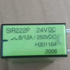
ELESTA (Swiss safety relay brand under Fungo) SIR4 Power high-current PCB-mount safety relay
- SIR: SIR4 series safety relay with forcibly guided contacts
- 222: Configurazione dei contatti: 2 Normalmente aperto (NO) + 2 Normalmente chiuso (NC) (dual-pole double-throw safety structure)
- P: High-current version rated for 12A load (standard SIR222 is 10A)
Standard stock coil specifications:
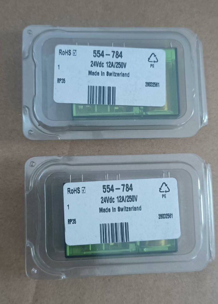
SIR222P 24VDC (mainstream, part number H301164, coil resistance 760Ω)
SIR222P 12VDC (part number H301192)
Custom coil voltages available: 5/6/18/48/110VCC
Core Safety Certifications
Conforme alla norma CEI 61810-3 Type A Forcibly Guided Contacts and EN50205 machinery safety standards. Applicable to machine tool and automated safety circuits to meet safety contact fault monitoring requirements.
- Mechanical Dimensions & Montaggio
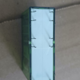
Overall size: 46.4(l) × 16(W) × 30.7(H) mm
Montaggio: Through-hole PCB soldering (14-pin footprint)
Peso: ca. 32G
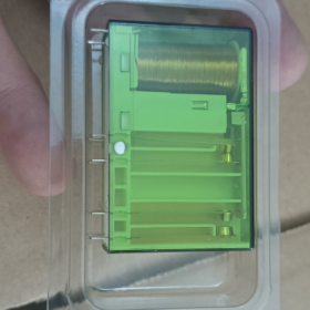
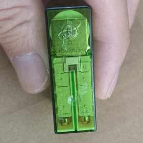
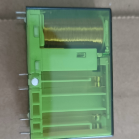
Alloggiamento: Transparent green dustproof flame-retardant PC, allows visual inspection of coil and contact status
Standard through-hole pin pitch for PCB mounting; compatible with dedicated PCB sockets
- Coil Electrical Parameters (DC)
| Articolo | Valore del parametro |
| Nominal pull-in coil power | 0.75W |
| Holding power consumption | 0.23W (low-power latching, bassa generazione di calore) |
| 24VDC coil resistance | 760Ω ±10% |
| Pull-in voltage range | 70%~110% della tensione nominale (DC 16.8~26.4V) |
| Tensione di caduta | ≤10% Un |
| Dielectric withstand voltage (coil to contacts) | 2500V AC for 1 minuto |
| Coil protection | Diodo di ricircolo incorporato (prevents reverse breakdown of DC coils) |
- Core Contact Electrical Ratings (2NO+2NC Safety Forced Linkage)
4.1 Capacità di carico (High-Current Advantage of SIR222P)
Continuous rated current: 12UN / 250VCA (AC1 resistive load)
Peak inrush current: Massimo. 60UN (20SM, suitable for inductive startup of motors and contactors)
Switching voltage range: AC 5~480V / DC 5~250V
Rated switching capacity: 3000VA
Minimum reliable switching load: 5mA / 5V (no sticking for weak signal circuits)
Materiale di contatto: AgSnO2 silver tin oxide, resistente all'arco elettrico e antisaldatura
4.2 Core Feature of Forcibly Guided Safety Design (Distinction from Standard Relays)
Forced mechanical linkage: NO and NC contacts within the same channel can never conduct simultaneously
Monitoring logic: Safety circuits can detect NC feedback signals to judge contact welding faults
Dielectric withstand voltage between contacts: 4000VCA; open contact withstand voltage: 1500VCA
Contact creepage distance: ≥10mm between coil and output contacts; ≥8mm between two output contact banks for enhanced isolation protection
4.3 Service Life Ratings
Vita meccanica: 10 million operations under no-load conditions
Vita elettrica (12A/250VAC resistive): 250,000 operazioni
Factory contact resistance: ≤100mΩ (tested at 6V/100mA)
- 14-Pin Pinout Definition (Standard Top Silkscreen Layout)
Perni della bobina (Drive Side)
13(+), 14(-): DC coil positive and negative terminals with built-in diode. Connect 14 to 0V and 13 to DC24V.
Two Independent Safety Contact Banks (1NO+1NC per bank with forced linkage)
Canale 1 (First Contact Bank)
1: Common COM1 | 2: NC Normally Closed | 3: NO Normally Open
Canale 2 (Second Contact Bank)
4: Common COM2 | 5: NC Normally Closed | 6: NO Normally Open
Pins 7~12 are unoccupied locating pins with no electrical connections.
- Environmental Operating Parameters
Temperatura operativa: -40℃ ~ +70 ℃
Temperatura di conservazione: -40℃ ~ +85 ℃
Umidità: 5%~95% RH non-condensing
Vibrazione / Resistenza agli urti: IEC60068 industrial equipment grade, suitable for machine tool and production line control cabinets
- Scenari applicativi tipici (Dedicated for Safety Circuits)
- Dual-channel monitoring for machine safety door and emergency stop circuits (NC contacts detect welding faults)
- Safe cut-off circuits for inverter and servo enable signals
- Output expansion for safety light curtains and safety mats on automated production lines
- Safety control circuits for rail transit, medical equipment and lifts
- High-current output expansion for PLCs (direct drive of contactors and solenoid valves up to 12A)
- Equipment fault diagnosis feedback (self-inspection of contact adhesion via NC contacts)
- Cross-Series Model Selection Comparison Table
| Modello | Configurazione dei contatti | Continuous Current | Potenza della bobina | Scenario applicativo |
| SIR222P | 2NO+2NC | 12UN | 0.75W | High-current safety circuits, contactor driving (primary recommended model) |
| SIR222 | 2NO+2NC | 10UN | 0.6W | Medium/low-current signal safety circuits |
| SIR312P | 3NA+1NC | 12UN | 0.75W | Multi-output single-channel monitoring |
| SIM222 | 2NO+2NC | 8UN | 1W | Compact low-load safety relay |
- Troubleshooting Matrix
| Fenomeno di guasto | Causa ultima | Soluzione |
| Coil energized but NO contacts fail to close | 1. Reversed coil polarity; 2. Supply voltage below 70% tensione nominale; 3. Bobina bruciata | Swap pins 13 E 14; Measure DC supply voltage; Replace relay |
| NO contacts stick closed after power-off, NC contacts cannot close (critical safety failure) | Load current exceeds 12A; repeated heavy arcing welds contacts | Reduce load or add intermediate relay; Install brand-new SIR222P |
| Both NC and NO contacts conduct during safety inspection | Damaged forcibly guided mechanical structure; relay cannot be repaired | Replace immediately; prohibit further use in safety circuits |
| Severe contact voltage drop and overheating | Poor PCB soldering; long-term near full 12A load | Re-solder PCB pins; Parallel additional contacts for current sharing |
| Coil shows no pull-in action at all | Open circuit at pins 13/14; No power supply output | Inspect power circuit and PCB solder joints for open connections |
- Mandatory Installation & Usage Prohibitions
- NC contact safety monitoring must not be omitted: Safety devices must read NC feedback signals; otherwise anti-welding protection is lost.
- Long-term resistive load shall not exceed 12A; inductive loads are recommended to be derated to 8A.
- DC coils must not be energized with reversed polarity for extended periods (built-in diode only provides one-time transient protection; sustained reverse voltage burns the coil).
- Prohibit full-load continuous operation above 70℃ in sealed cabinets; sufficient heat dissipation space must be reserved.
- Do not parallel contacts of different relays for current expansion; single-channel load cannot exceed rated current of one contact.
- Only PCB soldering mounting is allowed; avoid violent bending or repeated plugging/unplugging of pins.
- Standard Packing List
1 × SIR222P relay unit
- Original manufacturer safety datasheet, TÜV/CE safety certification documents
- Standard package quantity: 15 pezzi per scatola
Application Manual for ELESTA SIR222P Forcibly Guided Safety Relay
Document Version: V1.0|Applicable Models: SIR222P-24VDC (mainstream), SIR222P-12VDC
Marca: ELESTA (Svizzera)|Safety Standards: CEI 61810-3 Type A Forcibly Guided Contacts, EN50205, ISO13849-compliant safety circuit design
Table of Contents
- Panoramica del prodotto & Spiegazione del codice modello
- Complete Electrical Specifications
- Pinout Definition & Standard Wiring Specifications
- 4 Standard Industrial Wiring Schemes (Including Safety Circuits)
- PCB Mounting, Soldering & Mechanical Installation Standards
- Load Selection & Derating Guidelines
- Core Rules for Safety Circuit Design (Requirements for Forcibly Guided Contacts)
- Power-On Commissioning & Functional Test Procedures
- Troubleshooting Matrix
- Mandatory Installation & Usage Prohibitions
- Cross-Series Alternative Model Comparison
- Confezione & Documenti di certificazione
- Panoramica del prodotto & Spiegazione del codice modello
1.1 Model Code SIR222P
SIR: SIR4 Power series PCB-mounted forcibly guided safety relay
222: Contact structure: 2NO + 2NC, two independent banks of 1NO+1NC forced-linkage contacts
P: High-current version with 12A AC1 continuous rating per contact (standard SIR222 is only 10A)
1.2 Core Safety Features (Distinction from Ordinary Relays)
- Forcibly Guided Mechanical Structure: NO and NC contacts within one channel can never conduct simultaneously. If contacts weld shut, the paired opposite contacts remain open to enable fault diagnosis.
- Coil-to-contact dielectric withstand voltage: 2500VCA; inter-contact isolation: 4000VCA. Creepage distances meet safety isolation criteria.
- AgSnO2 silver tin oxide contacts with thin gold plating, anti-arcing and anti-welding, compatible with both high-current loads and weak signal detection.
- Built-in coil freewheeling diode (dedicated for DC coils to prevent reverse voltage breakdown).
1.3 Applicable Safety Performance Levels
Suitable for PLd / Cat.3, SIL2 safety cut-off circuits. Dual-channel redundant design achieves Cat.4 / Per favore.
- Complete Electrical Specifications
2.1 Parametri della bobina (DC)
| Articolo | SIR222P-24VDC | SIR222P-12VDC |
| Nominal pull-in power | 0.75W | 0.75W |
| Holding power consumption | 0.23W | 0.23W |
| DC coil resistance | 760Ω±10% | 190Ω±10% |
| Pull-in voltage range | 70%~110% Un (16.8~26.4VDC) | 8.4~13.2VDC |
| Tensione di caduta | ≤10% Un | ≤10% Un |
| Coil reverse protection | Diodo di ricircolo incorporato (Pin13+, Pin14-) | Diodo di ricircolo incorporato |
| Coil dielectric withstand voltage | 2500V AC for 1min | 2500V AC for 1min |
2.2 Contact Load Ratings (Per 1NO/1NC Channel)
- AC1 resistive: 12UN / 250VCA, max switching capacity 3000VA
- AC15 inductive (contattori / elettrovalvole): 8UN / 250VCA (derating mandatory)
- DC13 inductive: 5UN / 24VCC
- Peak surge current: 60UN (short-duration 20ms)
- Minimum reliable switching load: 5mA / 5V (no poor contact for PLC weak feedback signals)
- Materiale di contatto: AgSnO2 with 0.2~0.4μm gold plating
- Factory contact resistance: ≤100mΩ (6V/100mA test condition)
2.3 Service Life Ratings
Vita meccanica (nessun carico): 10 milioni di operazioni
Vita elettrica (12A/250VAC resistive): 250,000 operazioni
Vita elettrica (8A inductive load): 100,000 operazioni
2.4 Ambientale & Parametri meccanici
Dimensioni complessive: 46.4(l)×16(W)×30.7(H)mm, 14-pin through-hole PCB mount
Peso: 32G
Temperatura operativa: -40℃ ~ +70 ℃ (enhanced heat dissipation required for full load at 70℃)
Temperatura di conservazione: -40℃ ~ +85 ℃
Umidità: 5%~95% RH non-condensing
Resistenza alle vibrazioni: 10~55Hz, 1.5mm amplitude for 2 hours on each of three axes
Alloggiamento: Transparent green flame-retardant PC for visual contact inspection
- Pinout Definition (Top Silkscreen View, Standard PCB Footprint)
3.1 Coil Drive Pins
13: Coil positive DC+
14: Coil negative DC(cathode of built-in diode; sustained reverse connection prohibited)
3.2 Two Independent Forcibly Guided Contact Banks (COM+NC+NO per bank)
Canale 1 (First Safety Contact Bank)
1: Common COM1
2: NC1 Normally Closed (forced linkage feedback contact)
3: NO1 Normally Open (main power output)
Canale 2 (Second Safety Contact Bank)
4: Common COM2
5: NC2 Normally Closed (forced linkage feedback contact)
6: NO2 Normally Open (main power output)
3.3 Unoccupied Pins
Perni 7,8,9,10,11,12: Locating reinforcement only, no electrical connection, wiring forbidden.
3.4 Forced Linkage Logic (Core Safety Principle)
Coil de-energized (open state): Pins 2-NC1 and 5-NC2 conduct; Pins 3-NO1 and 6-NO2 open
Coil energized (pulled-in state): Pins 2-NC1 and 5-NC2 open; Pins 3-NO1 and 6-NO2 conduct
Fault judgment rule: If NC contacts remain closed after coil energization → NO contacts welded shut; safety circuit triggers fault and equipment shutdown.
- Four Standard Industrial Wiring Schemes
Schema 1: Dual-Channel Safety Cut-Off Circuit (Arresto di emergenza / Safety Door, Più comune)
Descrizione della funzione
Two independent NO contacts cut servo/inverter enable signals; two NC contacts connect to PLC for contact welding fault monitoring, complying with ISO13849 Cat.3 safety requirements.
Passaggi di cablaggio
- Coil drive: PLC 24V+ output → Pin13; 0V → Pin14
- Power output circuit (two independent cut-off paths, parallel connection prohibited)
Canale 1: 24VAC/DC supply → COM1(Pin1); NO1(Pin3) → Servo Enable Coil 1
Canale 2: 24VAC/DC supply → COM2(Pin4); NO2(Pin6) → Servo Enable Coil 2
- Fault feedback monitoring (NC contacts wired to PLC digital input)
NC1(Pin2) and NC2(Pin5) shorted together and connected to PLC PNP input; PLC logic: NC contacts must open when relay pulls in. Continuous conduction indicates contact welding and locks out equipment startup.
Mandatory Safety Rule
Two output loads must be independent. Parallel connection of NO1 and NO2 for current expansion destroys dual-channel redundant safety design.
Schema 2: PLC High-Current Output Expansion (Elettrovalvola / Contactor Drive)
Ambito di applicazione
PLC single-point output current ≤0.5A, insufficient for direct drive of 10A solenoid valves; SIR222P expands contact current capacity.
- Bobina: PLC output drives Pins13/14 (24VCC)
- Main circuit AC220V live wire → COM1(Pin1), COM2(Pin4)
- NO1(Pin3) and NO2(Pin6) parallel to solenoid coil (parallel allowed for resistive loads, not recommended for inductive loads)
- NC contacts unused or wired to alarm indicator light (light illuminates when relay de-energized)
Schema 3: Equipment Self-Diagnosis Circuit (Safety Light Curtain Output Expansion)
- Dual-channel NC signals from safety light curtain wired in series to drive relay coil Pins13/14
- Two NO contacts cut main contactor power supply; two NC contacts feed real-time contact status to PLC
- Logica: Curtain blocked → coil de-energized → NO contacts open and machine stops; If NC contacts stay closed with unobstructed curtain, relay contact damage is detected and alarm interlock activates.
Schema 4: Mixed Weak Signal & High-Current Circuit (Contact Channel Isolation)
- Channel1 NO contacts: Drive high-current AC220V contactors
- Channel2 NC contacts: Feed 5V weak feedback signal to MCU IO ports (gold-plated contacts guarantee stable low-current contact performance)
Prohibition: Do not share one contact bank for both high-current inductive loads and 5V weak signals; arcing contaminates contact surfaces and causes intermittent weak signal faults.
- PCB Mounting & Soldering Standards
5.1 PCB Pad Design Requirements
Pin hole diameter: 1.3mm, pad diameter ≥2.2mm
Standard pin pitch layout compatible with all 14-pin relays
Wider copper traces for COM/NO/NC high-current pins; copper thickness ≥35μm, trace width ≥5mm for 12A loads
5.2 Soldering Process Specifications
- Wave soldering peak temperature ≤260℃, contact duration ≤4s; hand iron temperature ≤350℃, single pin soldering time ≤3s
- Prolonged high-temperature heating of pins is forbidden, as it melts internal contact plastic supports
- Solder joints must be fully filled without cold solder or bridging between adjacent pins
- Clean flux residue after soldering to prevent leakage and creepage currents
5.3 Requisiti di dissipazione del calore
Continuous full 12A operation: Increase PCB copper trace heat dissipation area; cabinet ambient temperature ≤60℃
Ambient temperature of 70℃: Load must be derated to ≤8A
- Load Selection & Derating Standards
| Tipo di carico | Rated Permitted Current | Mandatory Derating Explanation |
| AC250V resistive (heating lamps, resistors) | 12UN | No derating required for long-term stable operation |
| AC250V inductive (contattori, elettrovalvole) | 8UN | Inductive kickback arcs occur at power-off; mandatory 1/3 declassamento |
| DC24V inductive (electromagnetic clutches) | 5UN | Poor DC arc extinction performance; significant derating required |
| Weak signal 5~24V (PLC feedback) | ≤0.5A | Only use gold-plated NC contacts; do not share channel with high-current loads |
Recommended Arc Suppression Measures
Fit absorption components across inductive load coils:
Carichi CA: RC absorption circuit (0.1μF capacitor in series with 100Ω resistor)
Carichi CC: Freewheeling diode wired in reverse parallel across coil terminals
- Mandatory Core Rules for Safety Circuit Design (Violation Invalidates Safety Certifications)
- NC contact monitoring cannot be omitted
All safety cut-off circuits (arresto di emergenza, safety doors, light curtains) must route both NC contact banks to the upper controller (PLC) for welding diagnosis. Circuits without monitoring fail to meet IEC61810-3 safety requirements.
- Dual-channel outputs must not be paralleled
Two NO contacts provide redundant safety cut-off; each must drive an independent load. Parallel connection eliminates fault isolation capability.
- Single-channel cut-off is prohibited for safety applications
Using only one NO contact to cut power while leaving the other unused downgrades safety classification directly to Cat.1 and fails machine safety acceptance tests.
- Do not series multiple safety relay contacts for current expansion
Multi-stage series connection increases contact failure probability and reduces safety level.
- Coil power supply must share the same source as the safety circuit. Separate power supplies cause asynchronous logic operation.
- Power-On Commissioning & Functional Test Procedures
8.1 Static Pre-Power Test (Multimeter Required)
- Coil de-energized state: Measure continuity between 1-2 E 4-5; open circuit between 1-3 E 4-6
- Measure coil resistance at Pins13/14 (760Ω for 24VDC model) to rule out short/open circuits
- Verify no continuity between unoccupied pins and coil/contact terminals
8.2 Energized Pull-In Test
- Apply rated DC24V to Pin13(+) and Pin14(-)
- Multimeter verification: Open circuit between 1-2 E 4-5; continuity between 1-3 E 4-6
- Cut coil supply voltage; contacts reset rapidly to original state
8.3 Safety Fault Simulation Test (Mandatory for Acceptance)
Manually simulate NO contact welding by shorting Pins1 and 3. With coil energized, NC1 (Pin2) remains conductive. PLC detects persistent NC closure and triggers fault alarm to validate the forcibly guided mechanical design.
- Troubleshooting Matrix
| Fenomeno di guasto | Causa ultima | Standard Resolution |
| Coil energized, NO contacts fail to close | 1. Reversed Pin13/14 polarity; 2. Supply below 70% E; 3. Open coil winding | Swap coil terminals, measure supply voltage, sostituire il relè |
| NO contacts stick closed after power-off, NC cannot close | Load exceeds 12A; no absorption circuit for inductive loads leading to arc welding | Install RC/diode absorption, derate load, sostituire il relè |
| Coil pulls in but NC contacts remain closed (critical safety failure) | Damaged forcibly guided mechanical linkage, seized contacts | Discard and replace immediately; ban use in safety circuits |
| Surriscaldamento dei contatti, voltage drop >1V | Poor PCB soldering, continuous 12A full load at high temperature, insufficient copper trace width | Re-solder joints, enlarge PCB heat dissipation traces, derate operating load |
| Intermittent PLC weak signal feedback | NC contacts previously carrying high-current loads with carbonized arc deposits on contact surfaces | Replace relay; separate high-current and weak signal channels |
| No coil pull-in action, zero voltage detected | Open circuit at Pins13/14, blown power fuse | Inspect PCB solder pads and 24V supply circuit |
| Leakage short between adjacent pins | Residual flux condensation, cabinet internal condensation | Clean PCB surface, improve cabinet dehumidification and ventilation |
- Absolute Installation & Usage Prohibitions
- Omission of NC contact welding monitoring on safety cut-off circuits voids safety certification validity.
- Continuous resistive loads exceeding 12A or inductive loads exceeding 8A burn contact sets.
- Long-term reverse energization of DC coils destroys the built-in freewheeling diode.
- Do not run continuous full 12A loads above 70℃ in sealed cabinets.
- Do not share one contact bank for both high-current inductive loads and 5V weak signal circuits.
- Parallel connection of two NO contacts for current expansion is forbidden in safety circuit applications.
- Prolonged full-load operation at ambient temperature above 70℃ is prohibited.
- Violent pin bending, repeated plugging/unplugging, and extended high-temperature soldering are forbidden.
- Do not deploy in circuits above AC480V, exceeding contact voltage withstand ratings.
- Cross-Series Alternative Selection Comparison
| Modello | Configurazione dei contatti | Per-Contact Rated Current | Potenza della bobina | Application Difference |
| SIR222P | 2NO+2NC | 12A AC1 | 0.75W | High-current safety cut-off, direct contactor drive (primary model) |
| SIR222 | 2NO+2NC | 10A AC1 | 0.6W | Medium/low-current signal safety circuits, low power consumption demand |
| SIR312P | 3NA+1NC | 12A AC1 | 0.75W | Multi-channel power output with single fault monitoring path |
| SIM222 | 2NO+2NC | 8A AC1 | 1W | Compact low-load PCB control boards |
- Confezione & Documenti di certificazione
12.1 Standard Packing List
1 × SIR222P-24VDC safety relay
- Original manufacturer datasheet
- Copies of CE and TÜV safety certification
- Standard carton quantity: 15 pezzi per scatola
12.2 Certificazioni di conformità
CE Industrial Equipment Certification
TÜV IEC 61810-3 Type A Forcibly Guided Contact Certification
EN50205 Machinery Safety Standard Compliance
RoHS Lead-Free Environmental Compliance Certification
 (IE5099 è il codice articolo dell'ordine; IEC3002-BPOG sta per il modello con specifiche di serie)")


")


")
NH42-63-318x560.png "Commutatori automatici di tipo PC CHINT (ATS)NH42-63/4SZ")


