 Contattore,interruttore automatico,inverter solare,contatore elettrico,batterie solari


Scomposizione del codice modello
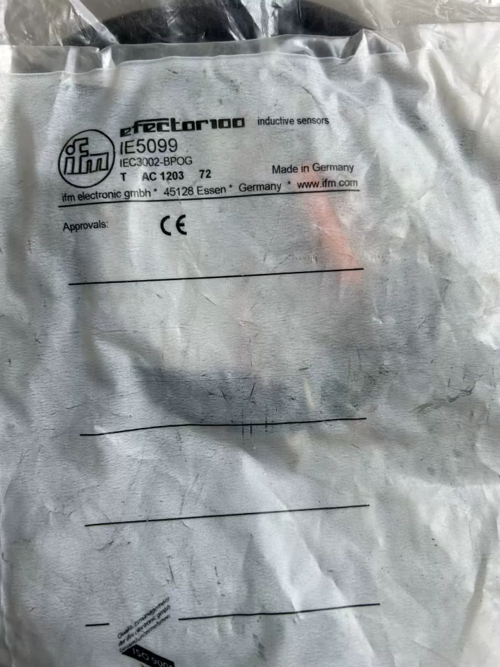
IE5099 = IEC3002-BPOG
(IE5099 è il codice articolo dell'ordine; IEC3002-BPOG sta per il modello con specifiche di serie)
- CEI: Series of inductive proximity sensori with M8 plastic thread IFM
- 3002: Rated sensing distance Sn = 2 mm
- B: 3-wire DC type
- P: Uscita PNP
- O: Normalmente aperto (NO)
- G: PVC straight cable (2m as standard factory length; 6m variant available as IE5100)
- Core Hardware Specifications
2.1 Mechanical Dimensions
Thread specification: M8×1.0, PBT plastic housing
Overall length: 35 mm, Non-flush mount design
Standard accessories: 2 pieces of M8 locking nuts
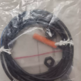
Cavo: 3×0.14 mm² PVC sheath, lunghezza standard 2 M
Peso netto: 43.1 G
Classe di protezione: IP67 (waterproof and dustproof, allows short-term washdown)
2.2 Parametri Elettrici (Official IFM Factory Standards)
| Articolo | Valore del parametro |
| Tensione di alimentazione | DC 10~36 V (compatible with standard industrial DC24V systems) |
| No-load Current Consumption | <15 mA (at 24 V operating condition) |
| Tipo di uscita | 3-wire DC PNP Normally Open (NO) |
| Massimo. Carica corrente | 200 mA (can directly drive PLC inputs and relay coils) |
| Output Voltage Drop | ≤2.5 V |
| Frequenza di commutazione | 800 Hz (suitable for high-speed counting and conveyor positioning) |
| Funzioni di protezione | Protezione da inversione di polarità, protezione da cortocircuito, protezione da sovraccarico |
| Rated Sensing Distance Sn | 2 mm |
| Stable Operating Range | 0~1.6 mm (reliable detection zone) |
| Actual Tolerance Sr | 2 ±10% mm |
| Hysteresis Range | 1%~15% of rated distance (anti-jitter design) |
| Switch Point Offset | ±10% Sr |
2.3 Material Correction Factors (Sensing Distance Attenuation)
Mild Steel St37: 1.0 (reference standard)
Acciaio inossidabile: 0.7
Ottone: 0.4
Alluminio: 0.3
Rame: 0.2
2.4 Environmental Operating Conditions
Temperatura operativa: -25℃ ~ +85℃
Temperatura di conservazione: -25℃ ~ +90℃
EMC Standards: IN 60947-5-2, EN55011 Class B
- Standard 3-Wire Wiring Definition (Global Uniform Color Code)
| Colore del filo | Definizione | Istruzioni di cablaggio |
| BN Brown | DC+ Positive Power Supply | Connect to 24V positive rail and PLC module 24V common terminal |
| BU Blue | DC- Negative Power Supply | Connect to 0V / power ground |
| BK Black | PNP Signal Output | Connect to PLC digital input terminal (attivo alto) |
PNP Wiring Logic
No metal target nearby: Black signal wire = 0 V, no input signal to PLC
Metal enters sensing zone: Black signal wire ≈ 24 V, PLC receives trigger signal
- Mounting Specifications (Mandatory Requirements for Non-flush Installation)
- Mounting Clearance (Prevent Mutual Interference)
Two sensors mounted side-by-side on the same axis: Center distance ≥12 mm
Adjacent side mounting: Gap ≥8 mm
- Detection Distance Control
Maintain the gap between metal target and sensing face within 0~1.6 mm. Signal loss will occur if the distance exceeds 1.6 mm.
- Coppia di serraggio
Tightening torque for M8 nuts: 0.8~1.2 N·m. Do not over-tighten to avoid cracking plastic threads.
- Wiring Separation Rules
Maintain a minimum clearance of 30 cm between sensor cables and power cables for inverters / contattori. Route wires perpendicularly when crossing to reduce interference.
- Cable Protection
Avoid long-term bending and crushing; reserve a 5 cm slack buffer at cable joints.
- Scenari applicativi
- Workpiece presence detection on assembly lines, conveyor counting, high-speed indexing positioning (800 Hz high-frequency operation)
- Metal presence detection on automated machine tools, cylinder piston position feedback
- Macchine per l'imballaggio, logistics sorting, material counting on conveying equipment
- Compatible with digital inputs of full series PLCs: Omron CJ/CP/NJ, Siemens S7, Mitsubishi FX/Q
- Cross-Series Alternative Model Comparison
| Modello | Distanza di rilevamento | Tipo di uscita | Lunghezza del cavo | Differenza |
| IE5099 IEC3002-BPOG | 2 mm | PNP NO | 2 M | Standard general-purpose model |
| IE5100 IEC3002-BPOG/6M | 2 mm | PNP NO | 6 M | Long cable for long-distance wiring |
| IE5098 IEC3002-BPKG | 2 mm | PNP NC Normally Closed | 2 M | For applications requiring NC signal |
| IE5089 IEC3002-BNOG | 2 mm | NPN NO | 2 M | Replacement for NPN-type PLC input systems |
- Troubleshooting Matrix
| Fenomeno di guasto | Causa ultima | Soluzione |
| Yellow LED off and no signal output when metal target approaches | 1. Reversed brown/blue power wires; 2. Supply voltage below 10 V; 3. Cavo rotto | Verify wiring polarity, measure DC24V supply, inspect cable segments for breaks |
| Yellow LED stays lit even without metal target | 1. Excessively short mounting gap; 2. Interference from surrounding metal brackets; 3. Internal output transistor breakdown | Widen mounting clearance, remove surrounding metal obstructions, replace the sensor |
| Flickering, intermittent signal | 1. Cable runs close to high-power sources causing interference; 2. Target moving speed exceeds 800 Hz; 3. Loose nuts leading to distance drift | Fit ferrite core on cable for shielding, reduce moving speed, retighten and secure nuts |
| No PLC input signal but sensor yellow LED works normally | 1. Loose black signal wire connection; 2. Mismatched polarity of PLC input common terminal; 3. Load current over 200 mA | Tighten terminals of black wire, confirm 24V common terminal for PNP modules, add intermediate relay for load expansion |
| No LED indicator light on sensor at all | Open circuit in power supply loop, blown power fuse | Inspect DC24V circuit breaker and terminal block wiring |
- Strict Installation & Usage Prohibitions
- Do not embed flush into metal brackets. This model is designed exclusively for non-flush mounting. Embedding will drastically shorten sensing distance or cause complete failure.
- Do not exceed total load current of 200 mA; otherwise the output transistor will burn out.
- Do not immerse cable in oil, strong acid or alkali for long periods; PVC cables are not resistant to highly corrosive media.
- Do not connect directly to AC220V mains; only DC 10~36V power supply is supported.
- Do not bundle multiple sensor cables with power cables for long-distance parallel routing in the same trunking.
- Standard Packing List
- 1 × IE5099 sensor main unit (with 2m 3-core PVC cable)
- 2 × M8 plastic locking nuts
- Original manufacturer operation manual, CE certification documents
Full Specification of Switching Frequency for IFM IE5099 (IEC3002-BPOG)
- Official Rated Parameter
Standard Switching Frequency: 800 Hz (rated value under DC operation)
Definizione: The sensor can complete a maximum of 800 full switching cycles per second: metal enters sensing zone → output ON; metal leaves sensing zone → output OFF.
Response Cycle Conversion
Single full switching cycle = 1 ÷ 800 = 1.25 SM
The sensor features ultra-fast total response time including internal detection and output toggle, ideal for high-speed dynamic detection applications.
- Key Supporting Dynamic Parameters (Critical for Stable High-Frequency Operation)
- Isteresi: 1%~15% Sr
Sr = 2 mm (rated sensing distance), hysteresis range: 0.02~0.3 mm
Funzione: Eliminate frequent false signal triggering caused by mechanical vibration and tiny jitter, balancing high-speed response and anti-interference performance.
- Stable Effective Detection Zone: 0~1.6 mm
Detection sensitivity drops sharply beyond 1.6 mm, leading to frequent pulse loss under high-frequency working conditions.
- Output Driving Capacity
Massimo. corrente di carico 200 mA. Can be wired directly to PLC high-speed input terminals without intermediate relay expansion for high-speed counting.
- Calculation of Equipment Linear Speed at 800 Hz (On-site Selection Reference)
Esempio: Metal baffles evenly arranged on conveyor, each baffle 1 mm thick with 1 mm gap between adjacent pieces
Total width of one metal piece plus gap = 2 mm
Massimo. number of workpieces passing per second = 800
Linear speed = 800 × 2 mm = 1600 mm/s = 1.6 m/s
Meets requirements for conveyor belts, indexing plates, high-speed stamping positioning and encoder synchronous counting;
Higher linear speeds are achievable with thinner workpieces and smaller gaps.
- High-Frequency Operation Limitations & Precauzioni
- Sensing Distance Attenuation by Metal Material Reduces Max. Stable Switching Frequency
Mild Steel: Correction factor 1.0, stable full-speed operation at 800 Hz
Acciaio inossidabile (0.7), Ottone (0.4), Alluminio (0.3), Rame (0.2): Effective sensing distance decreases, resulting in lower actual stable switching frequency. Reduce mounting clearance accordingly.
- Wiring Interference Degrades Effective Frequency
Parallel routing of sensor cables with inverter / contactor power cables without shield grounding introduces high-frequency noise, causing pulse loss and signal flickering.
Countermeasure: Maintain ≥30 cm clearance between signal and power cables, cross wires perpendicularly, implement single-point shield grounding inside control cabinets.
- Excessive Load Is Forbidden
Frequent high-speed switching with load current approaching the 200 mA upper limit causes output heating and reduced maximum switching frequency. Pieno 800 Hz performance can be maintained when driving low-current PLC inputs (<10 mA).
- Mounting Regulation Restrictions
This sensor is an M8 plastic-thread Non-flush type. Embedding into metal bases weakens magnetic fields and severely impairs high-frequency response. Center distance between two side-by-side sensors shall be ≥12 mm to avoid magnetic field crosstalk and pulse dropout.
- Cross-Series Horizontal Comparison (Reference for High-Frequency Selection)
| Modello | Frequenza di commutazione | Housing Type | Application Difference |
| IE5099 IEC3002-BPOG | 800 Hz | M8 plastic thread straight cable | General medium-high speed assembly lines, cylinder position detection |
| IFB3002-BPKG (M12 metal) | 1400 Hz | Metal thread connector type | Ultra-high speed indexing, high-speed counting |
| IEK3002-BBPOG | 1000 Hz | M8 metal thread | Balanced speed and mechanical impact resistance |
- Typical High-Frequency Application Scenarios
- High-speed workpiece counting for packaging & logistics conveyor belts
- High-speed position feedback for rotary indexing tables and cams
- Rapid position confirmation for stamping equipment and robotic manipulators
- Pulse acquisition for PLC high-speed counter modules (CJ1W-CT021, Siemens 224XP high-speed inputs)
- High-Frequency Fault Diagnosis (Insufficient Switching Frequency / Pulse Loss)
| Fenomeno | Causa ultima | Soluzione |
| Normal counting at low speed, pulse loss at high speed | 1. Mounting gap over 1.6 mm; 2. Severe attenuation from aluminum/copper targets; 3. Cable interference | Reduce detection gap; replace targets with steel; separate signal and power wiring |
| Flickering yellow LED and unstable output under 800 Hz operation | Load current approaching 200 mA upper limit | Install series intermediate relay to lower sensor output load |
| Mutual interference between multiple sensors running high-frequency detection on one track | Mounting center distance less than 12 mm | Increase center spacing of side-by-side sensors |
 SIR4 Relè di sicurezza di potenza per montaggio su PCB ad alta corrente")


")


")
NH42-63-318x560.png "Commutatori automatici di tipo PC CHINT (ATS)NH42-63/4SZ")


