 コンタクタ,サーキットブレーカー,ソーラーインバーター,電気メーター,太陽電池


基本情報
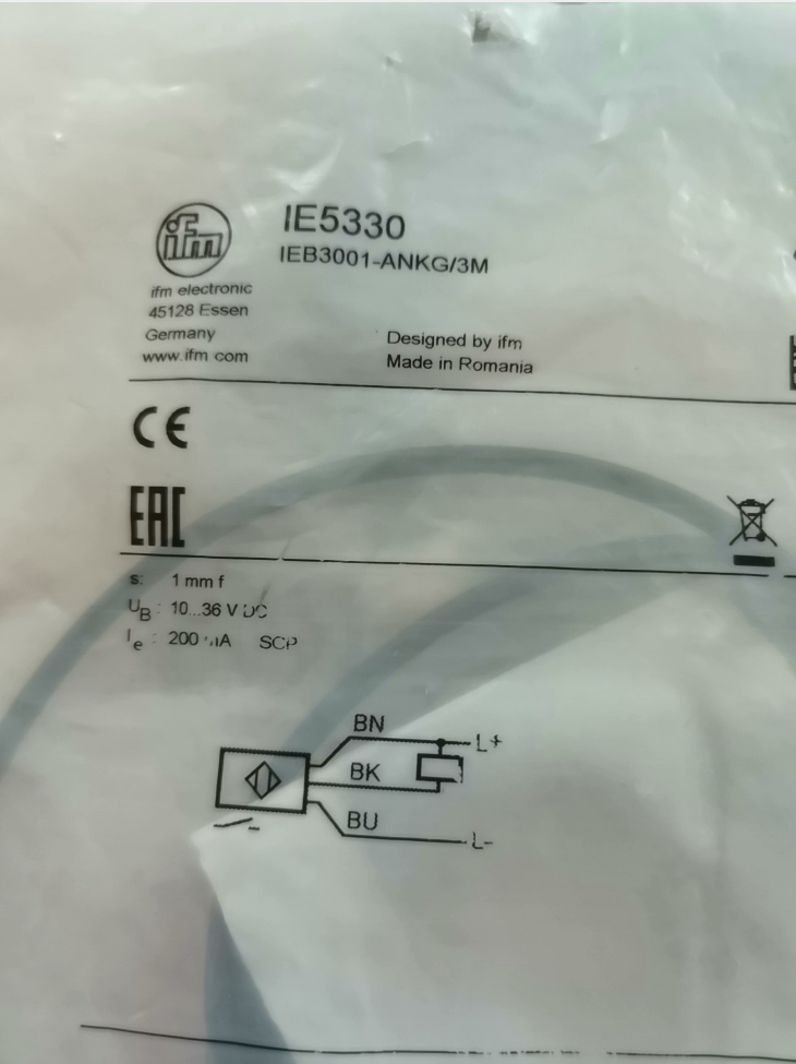
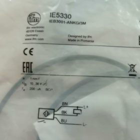
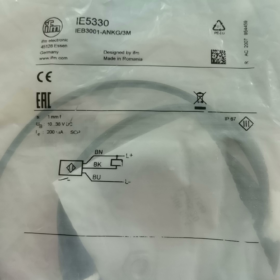
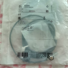
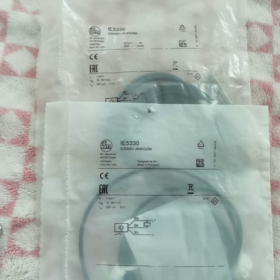
Full Model Code: IFM IEB3001-ANKG/3M (Commercial Model: IE5330)
製品タイプ: M8 Shielded Inductive 近接センサー (Flush Mountable)
End-of-Life Notice: Officially discontinued by manufacturer on Mar 31, 2026; replacement selection required.
コア仕様
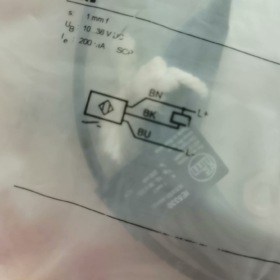
Thread Size: M8×1, Overall Length: 35 mm
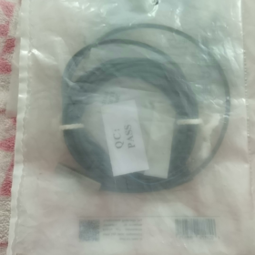
ケーブルコンセント: 3m PVC 3-core straight cable
出力: NPN Normally Open (いいえ)
検出距離: 標準 1 mm (shielded flush type)
- コアの電気パラメータ
電源
動作電圧: DC 10~36 V (compatible with standard 24V industrial control systems)
Quiescent Current: 15 mA @ 24 V
内蔵保護機能: 逆極性保護, 短絡保護, 過負荷保護
出力特性
出力タイプ: NPN Open Collector (Sink Output)
出力モード: 通常開 (conducts when metal approaches)
最大負荷電流: 200 ミリアンペア
Voltage Drop at Turn-On: ≤2.5 V
スイッチング周波数: 750 Hz (suitable for high-speed counting)
Sensing Performance
Rated Sensing Distance Sr: 1 mm ±10%, Effective Operating Range: 0~0.8 mm
Metal Correction Factors:
ヒステリシス: 1%~15% of Sr (prevents signal chattering)
- 機械式 & 環境パラメータ
- ハウジング材質: Bronze-plated brass; sensing face: PBT plastic
- 保護クラス: IP67 (防水 & 防塵, withstands short-time rinsing)
- 取付方法: Flush shielded design (fully embeddable in metal brackets)
- Supplied Accessories: 2 pieces of M8 lock nuts as standard
- 動作温度: -25 ℃ ~ +80 ℃
- EMC コンプライアンス: Industrial standards EN55011 Class B, EN60947-5-2
- 3-Wire Wiring Definition (3mケーブル)
| ワイヤーの色 | 関数 | Wiring Instruction |
| 茶色 | DC+ 24V Positive | Connect to 24V terminal of PLC / 電源 |
| 青 | 直流- 0V Negative | Power common ground |
| 黒 | NPN Signal Output | Connect load between 24V+ and black wire |
PLC Wiring Notes (NPN Sink Type)
Directly compatible with Japanese PLCs (三菱 / オムロン);
European standard PNP source-type PLCs require an intermediate relay for signal conversion.
- 典型的なアプリケーションシナリオ
Position detection of small cylinders, positioning of miniature tooling fixtures
Counting metal workpieces on miniature conveying lines (750Hz high frequency)
Installation in compact equipment spaces (short slim M8 housing, L=35mm)
Metal detection for machine tools, automated assembly lines and 3C equipment
- Recommended Replacement Models After Discontinuation (Direct Drop-In Compatibility)
Identical Spec Drop-In Replacement (M8 shielded, 1mm, NPN いいえ, 3メートルケーブル)
- IE5331: New upgraded generation with fully identical parameters, abundant stock
- IEB3002-ANKG/3M (new series part number)
Alternate Output Versions
PNP Normally Open equivalent: IE5340
Unshielded M8 long sensing distance (2 mm): IE5090
- 一般的なトラブルシューティング マトリックス
| 故障現象 | 根本的な原因 | ソリューション |
| No indicator light, complete failure to operate | 茶色 & blue wires reversed; supply voltage below 10V | Verify wiring sequence, measure 24V power supply |
| No signal output when metal approaches | Detection gap over 0.8mm; excessive attenuation for aluminum/copper targets | Reduce mounting clearance; replace target with steel sensing plate |
| Frequent signal chattering | Loose mounting nuts; insufficient hysteresis; severe mechanical vibration | Tighten lock nuts, shorten detection distance |
| Output fails several seconds after power-on | Output short-circuit triggering built-in protection lockout | Disconnect load, power cycle to locate short circuit |
Key Distinction Points for Model Selection
- IE5330 Shielded Flush Type: 1検出距離mm, embeddable into metal holders, strong anti-interference capability;
- Unshielded M8 model IE5070: 2検出距離mm, non-embeddable, susceptible to interference from surrounding metal;
- Plug-in versions have no “/3M” suffix at model end; cable versions come with fixed 3-meter cable.
Complete Troubleshooting Guide for IFM IE5330 (M8 Shielded, NPN いいえ, 1mm)
Precondition Reference Parameters (Benchmark for Troubleshooting)
- 電源: DC 10~36 V, 3-ワイヤーシステム: Brown = 24V+, Blue = 0V, Black = NPN NO signal output
- Rated sensing distance Sr = 1mm (shielded flush design, effective working gap ≤0.8mm)
- Max load 200mA, built-in reverse polarity, short-circuit and overload protection
- インジケータ: 黄色のLED; lit when metal approaches, off without metal target
- IP67 protection class, 動作温度: -25 ℃ ~ +80 ℃
- Standard Layered Troubleshooting Procedure (Simple First, On-Site Priority)
層 1: 目視検査 & 機械的取り付け (5-Min Preliminary Check)
- Clean sensing face: Remove iron filings, cutting fluid, oil stains and dust; adhered metal debris causes continuous false triggering / permanent ON state
- Inspect housing & ケーブル: Check for crushed insulation, broken conductors from bending, water ingress whitening, loose lock nuts
- Mounting Specifications (IE5330 is shielded flush type)
Fully embeddable inside metal brackets; side surrounding metal generates no interference
Detection gap must be ≤0.8mm; target surface perpendicular to sensing face
Minimum spacing ≥ 3×Sr = 3mm for multiple sensors mounted side-by-side to avoid mutual interference
- Metal Target Correction Factors (Primary cause of sensing distance attenuation)
層 2: Multimeter Test for Power Supply & 配線 (High-Frequency Fault Source)
- Cut off power to verify wiring: Brown connected to 24V+, Blue to 0V, Black to PLC input (NPN sink)
- Power on and measure voltage across brown & blue terminals: Stable 10~36V required, 波紋 <5%; sensor fails to start if voltage drops below 10V
- Reverse polarity lockout: Swapped brown/blue wires activate protection lockout, yellow LED stays off; power off for 3 minutes to reset and restore function
- Cable open circuit: Test continuity segmentally for brown, blue and black wires; cable inside cable chains for machine tools is most prone to breakage
- PLC Compatibility Note: IE5330 is NPN NO; PLC input common terminal must connect to 24V+. Direct connection to European PNP-type PLCs yields no signal; an intermediate relay is required for conversion.
層 3. Electrical Output Functional Test (Judge Sensor Integrity via Multimeter)
Standard voltage states of NPN NO IE5330 (measure black wire against blue wire 0V):
No metal target: Black wire ≈ DC24V (high level, yellow LED off)
Steel plate close to sensing face: Black wire ≈ 0~2.5V (low level, yellow LED ON)
Test Judgment Criteria:
- Normal voltage switching synchronized with yellow LED → Sensor intact; fault lies in downstream PLC / 配線
- No voltage variation, LED unresponsive to metal movement → Sensor damaged or locked out by short-circuit protection
層 4. 電磁妨害 & 環境検査 (Exclusive for Signal Chattering)
- Sensor cables routed parallel with inverter / servo power cables → High-frequency noise causes random signal fluctuation
- Long-distance unshielded cables with both ends of shield grounded (shield shall only be grounded at control cabinet single end)
- Magnetic interference generated by frequent switching of nearby welders, solenoid valves and contactors
- Ambient temperature exceeding 80 ℃ causes internal circuit drift and intermittent signal loss
- Fault Phenomenon Matrix (現象 + 根本的な原因 + One-Step Solutions)
故障 1: Yellow LED never lights up after power-on, zero output
| 根本的な原因 | Quick Check | 是正措置 |
| Reversed power polarity (brown & blue swapped) | Multimeter detects reversed voltage polarity between brown & 青 | Swap brown and blue power wires; power off and rest 3 mins for reset |
| 電源電圧 <10V or missing 24V rail | Voltage between brown & 青 <10V / 0V | Replace regulated 24V DC power supply; upgrade wire gauge to reduce voltage drop |
| Internal breakage of brown / blue wires in cable | Segmental continuity test | Cut damaged section and re-crimp terminals, or replace entire 3m cable |
| Internal sensor burnout from overvoltage | Voltage previously exceeded 36V, lightning surge | Directly replace IE5330 or substitute model IE5331 |
| Tripped fuse on upstream circuit | 短絡 / overload protection triggered | Locate downstream short circuit, replace fuse then restore power |
故障 2: Yellow LED permanently ON with no metal target nearby
- Iron filings / metal powder adhered to sensing face
解決: Wipe sensing face with alcohol; install dust shield baffle
- Over-tight detection gap, metal base tightly attached to sensor head
解決: Raise sensor with gaskets; control clearance at 0.4~0.8mm
- Short circuit between black output wire and 24V positive
解決: Cut power, separate damaged cable insulation and isolate short points
- Internal breakdown of output transistor
解決: Test with identical spare sensor; replace if faulty
故障 3: Yellow LED lights when metal approaches, yet no PLC input signal
- PLC input common terminal connected to 0V (PNP configuration incompatible with NPN sensor)
解決: Reconnect PLC COM terminal to 24V+
- Open circuit on black output wire; loose / oxidized terminals
解決: Fasten terminals tightly, test black wire continuity and repair breaks
- Load current exceeds 200mA (direct drive of large solenoid valves)
解決: Switch via intermediate relay; prohibit direct connection of high-power loads
- Burned PLC input channel
解決: Move black wire to spare healthy input channel for verification
故障 4: Chattering, intermittent signal, frequent false triggering / missed detection
- Detection gap near critical threshold of 0.8~1mm
解決: Shorten clearance below 0.5mm for sufficient trigger margin
- Severe machine vibration loosens sensor nuts and shifts position
解決: Double lock nuts with anti-loose washers
- Interference from power cables laid parallel with sensor wiring
解決: Separate cable trays, cross wires perpendicularly; ground cable shield only at control cabinet end
- Target made of aluminum / stainless steel with heavy sensing distance attenuation
解決: Fit steel sensing gaskets, reduce detection gap
- 過剰な電源リップル, poor filtering of switching power supply
解決: Connect 1000μF/35V electrolytic capacitor in parallel to power output terminal
故障 5: Yellow LED extinguishes several seconds after power-on, output disabled (intermittent protection lockout)
- Output wiring shorted to ground (black wire touching 0V)
解決: Disconnect black wire of sensor and power on alone; LED recovery indicates downstream short circuit, inspect wiring segmentally
- Load short-circuit / instantaneous overload triggers built-in short-circuit protection
解決: Remove downstream load, test sensor under no-load condition
- Cable insulation damaged, persistent micro-short between black and blue wires
解決: Replace complete cable assembly
故障 6: Abnormal operation under extreme hot / cold conditions (malfunction at high/low temperature)
- 周囲温度以上 80 ℃ exceeding rated upper limit
解決: Install air-cooled heat shield baffle; relocate away from cylinder heating blocks and welding stations
- Cable hardening and breakage below -25 ℃ low temperature
解決: Replace with low-temperature flexible cable; fix routing to reduce repeated bending
- On-Site Quick Self-Test Operation Steps (No Disassembly Required)
- No-load sensor test (disconnect PLC load)
Connect only brown to 24V, blue to 0V, leave black wire unconnected; place steel plate near sensing face and observe yellow LED:
Synchronous ON/OFF switching → Sensor body intact
No variation / permanently ON / permanently OFF → Sensor damaged
- Cross-Comparison Test (Most Efficient Judgment Method)
Install confirmed good IE5331 / IE5330 at faulty position with unchanged wiring:
Fault eliminated = Original sensor defective
Fault persists = Issue with power supply, 配線, PLC or mounting
- Short-Circuit Protection Reset Procedure
After short-circuit lockout: Fully disconnect brown and blue power wires, cut power for ≥3 minutes then re-energize for automatic built-in protection reset.
- Hard Rules for Mounting & 配線 (Avoid Recurring Failures)
- Do not subject cables to long-term compression or repeated 90° bending (prone to internal conductor breakage)
- Signal cables must not be laid parallel with inverter / servo power cables in the same trunking
- Shielded cable shielding shall be grounded at single end only; double-end grounding introduces circulating current interference
- Although IE5330 shielded version can be embedded into metal, avoid long-term high-temperature baking against thick steel plates
- Forbid direct drive of 24V high-power solenoid valves (loads over 200mA must be switched via relay)
- Strictly prohibit supply voltage exceeding DC 36V; add surge absorption diodes if no regulated power supply is used
- Spare Part Replacement Scheme (When IE5330 Discontinued & Unrepairable)
- Direct drop-in replacement: IE5331 (fully matching parameters, NPN いいえ, M8 shielded, 1mm sensing, 3メートルケーブル)
- Alternate output type: Identical-size PNP NO model IE5340
- Long-distance sensing demand: Unshielded M8 2mm IE5090
- Routine Preventive Maintenance (Reduce Failure Rate)
- 日常点検: Wipe iron filings and cutting fluid off sensing face; check lock nuts for tightness
- Weekly Cable Inspection: Check cables inside drag chains for insulation damage, aging and tensile strain
- Monthly Power Check: Monitor stability of 24V output voltage via multimeter
- High-interference Production Lines: Inspect shield grounding terminals quarterly for oxidation and looseness


")

")
 4MB容量の3.3V産業用フラッシュを採用. S7-1200専用設計です。, S7-1500 PLC、SINAMICS G/S/V シリーズ インバータおよびサーボ ドライブ.")
 とMHT2-50D (エンドクランプグリッパー)")


")
NH42-63-318x560.png "CHINT PC型自動切替スイッチ (ATS)NH42-63/4SZ")


