 コンタクタ,サーキットブレーカー,ソーラーインバーター,電気メーター,太陽電池

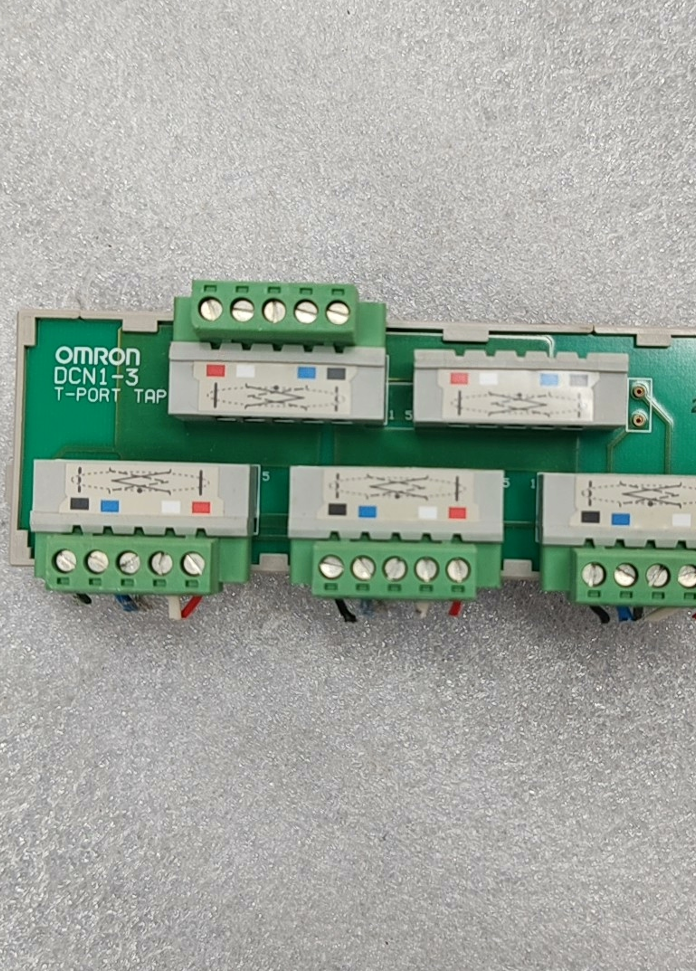

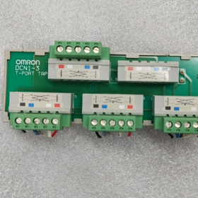
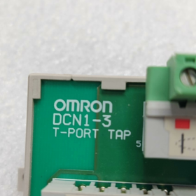
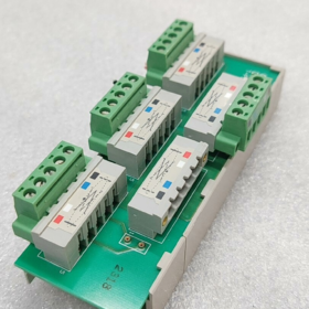
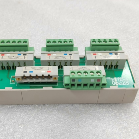
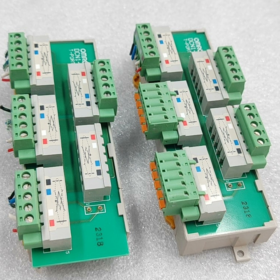
DCN1-3T-ポート = DCN1-3. 業界では一般に DeviceNet T 分岐スプリッタとして知られています / 3-ポートTAP端子台, it is printed with the marking “T-PORT TAP” and serves as a dedicated branching module for オムロン DeviceNet fieldbus.
Model Suffix Differentiation (Mandatory Reading for Procurement)
| モデル | Configuration Description |
| DCN1-3 (bare unit) | Base only, without 5 sets of terminal blocks; XW4B terminals must be ordered separately |
| DCN1-3C | Standard equipped with 5 side-entry screw terminals (most widely used in industry) |
| DCN1-3NC | Top-entry latch-type terminals for screw-free fast wiring |
- Hardware Port Structure (5-channel 5-pin DeviceNet Standard)
- 2 Main Line Ports: Bus trunk line input and output for daisy-chain networking
- 3 Branch Ports: までサポート 3 DeviceNet slave devices connected simultaneously (センサー, remote I/Os, インバータ)
- Built-in Terminating Resistor Socket: Blue plug-in terminal on the module side. A 121Ω terminating resistor must be inserted at the bus end to suppress signal reflection
ピンの定義 (Standard 5-pin DeviceNet):
1: V− (Power Negative), 2: CAN_L, 3: CAN_H, 4: V+ (Power Positive), 5: Shield Ground
Ⅲ. コア電気 & 機械仕様
- Electrical Ratings
Bus Standard: DeviceNet 2.0A / 2.0B
供給電圧: DC 11~24V (bus-powered)
Single Branch Current Rating: マックス. 4あ; Total module rated current: 8あ
Matching Terminating Resistor: Built-in mounting position, supplied with 121Ω / 0.25W resistor
Supported Baud Rates: Full range 125k / 250k / 500 kbps
- 環境 & Mounting Specifications
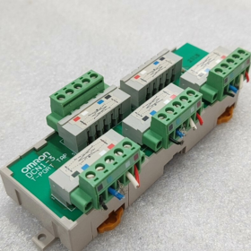
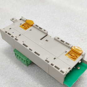
取り付け: Snap-on mounting on standard 35mm DIN rail
全体の寸法: 142(L) × 45(W) × 31.3(D) mm
正味重量: 110 g
動作温度: -10℃ ~ +55℃
保管温度: -25℃ ~ +70℃, Humidity 5%~95% non-condensing
保護クラス: IP20 (for cabinet installation only; not for outdoor exposed use)
- Networking Principle & アプリケーションシナリオ
- Network Topology
The two main ports of DCN1-3 are directly connected to the trunk line, with independent equipment tapped off the 3 branch ports.
利点: No on-site wire stripping and jointing required; faults on one branch are isolated without disrupting communication on the entire bus.
制限: Total cable length per branch must comply with DeviceNet specifications (最大. 100 m per branch at 500 kbps).
- Typical Industrial Applications
Automotive assembly lines, 包装機械, logistics sorting lines
Branch splitting for Omron DeviceNet remote I/Os (DRT series), 3G3MV / 3G3RX inverters, E3Z / E2E bus sensors
- 包装内容明細書 & オプションのアクセサリ
Standard Factory Package for DCN1-3C
- 1 × DCN1-3 Main Unit
- 5 sets of 5-pin screw terminals XW4B-05C1-H1-D
- 1 × 121Ω bus terminating resistor
Separately Orderable Accessories
DCN1-3 (terminal-less version): Terminals need to be purchased additionally
DCN1-1 / DCN1-2: Compact 1-port / 2-port TAPs (alternative models within the same series)
DCA1 series DeviceNet bus cables, pre-assembled M12 connectors
- 一般的なトラブルシューティング マトリックス
| 故障現象 | 根本的な原因 | 解決 |
| Branch devices undetectable during bus scan | Loose terminal crimping; CAN_H / CAN_L reversed | 端子の増し締め; verify pin assignment for red and blue signal wires |
| Severe communication lag & packet loss across the whole bus | No terminating resistors fitted at both bus ends | Insert matching resistors into the DCN1 module at the far end of the link |
| No power supply to branch devices after power-on | Loose crimps on V+ / V− power cables | Inspect wiring on pins 1 そして 4 |
| Frequent disconnection of single-branch devices | Excessively long branch cables; ungrounded shielding | Shorten branch cables; connect shield terminals to cabinet earth bar |
Ⅶ. Cross-Series Alternative Comparison
| モデル | Number of Branches | Cable Entry Type | アプリケーションシナリオ |
| DCN1-1C | 1 branch | Side screw terminals | Short branch for single-point devices |
| DCN1-2C | 2 branches | Side screw terminals | Compact layout with two slave devices |
| DCN1-3C | 3 branches | Side screw terminals | Central multi-way splitting (mainstream model) |
| DCN1-4C | 4 branches | Top entry | Dense cabinet layout with multiple devices |
インストールを完了する & Configuration Manual for OMRON DCN1-3 (DCN1-3T-PORT)
The DCN1-3 is a dedicated T-type 3-way branching terminal block for DeviceNet (commonly referred to as T-PORT). The whole operation consists of six steps: Mechanical Mounting → Terminal Wiring → Terminating Resistor Setup → Network Topology Compliance → PLC Software Configuration → Power-On Test. All operations must be performed with power disconnected.
- Preparatory Tools & 材料
- Standard Supplied Materials (DCN1-3C terminal-equipped version)
DCN1-3 main unit, 5 sets of 5-pin screw terminals XW4B-05C1-H1-D, 1 × 121Ω terminating resistor
- ツール
Flathead screwdriver, ワイヤーストリッパー, dedicated 5-core shielded DeviceNet cable (Red = V+, Black = V−, White = CAN_H, Blue = CAN_L, Bare wire = Drain Shield)
- ソフトウェア
CX-Programmer + CX-Integrator (Omron DeviceNet network configuration tool)
- ステップ 1: Mechanical DIN Rail Mounting (Power Disconnected)
- Rail Latches: Upper and lower latches are located at the unit bottom. Hook onto the top edge of a standard 35mm DIN rail first, then press down the bottom latch until a click sound confirms locking.
- 除去: Pinch the bottom latch outward and lift upward to detach the unit.
- Alternative Fixing: If no DIN rail is available, fasten the unit to the cabinet backplate via Φ3.5 mounting holes on both sides.
- 環境要件: IP20 rated, for cabinet interior use only. Keep away from high-interference sources such as inverters and contactors; operating environment range: -10~+55℃.
Ⅲ. ステップ 2: 端子の定義 & 標準配線 (Core Procedure)
- Unified 5-Pin Pinout (Identical for all terminals)
| ピン番号. | ワイヤーの色 | 信号名 | 機能の説明 |
| 1 | 黒 | V− | 24V bus power negative |
| 2 | 青 | CAN_L | Communication differential negative signal wire |
| 3 | 白 | CAN_H | Communication differential positive signal wire |
| 4 | 赤 | V+ | 24V bus power positive |
| 5 | Bare Copper Wire | Drain Shield | Cable shield grounding |
- Distinction of 5 端子 (2 Main Line Ports + 3 Branch Ports; Trunk lines must connect to the two marked terminals)
ターミナル 1 (): Trunk IN (Input from PLC master station / preceding bus segment)
ターミナル 2 (): Trunk OUT (Output to next bus segment)
> キーノート: The two terminals are directly connected with minimal internal resistance and must carry the main trunk line. The remaining 3 unmarked terminals are branch ports for external slave devices including DRT remote I/Os, inverters and bus sensors.
端子 3/4/5: Independent branch outputs for Branch 1 / 2 / 3
- Terminal Wiring Procedures
- Pull out the XW4B terminal block and loosen all set screws.
- Strip 5 mm insulation from cable ends; crimp bare drain shield wire separately to Pin 5.
- Insert wires strictly in the order: Red to Pin4, Black to Pin1, White to Pin3, Blue to Pin2, then fully tighten screws (Multiple wires in one pin hole are prohibited).
- Reinstall the terminal block and confirm no loose wiring or exposed conductors.
- Shield Grounding Rule: Single-End Grounding. Connect Pin5 shield to the earth bar only inside the PLC master cabinet; leave shielding floating at remote device ends to avoid circulating current caused by double-ended grounding which disrupts communication.
- ステップ 3: Terminating Resistor Installation (Critical for Stable Communication; Common Error Point)
- A dedicated black socket on the right side of the DCN1-3 unit is reserved for the supplied 121Ω terminating resistor.
- ルール: Only fit one 121Ω resistor at each physical extreme end of the entire DeviceNet trunk line; no terminating resistors shall be fitted on any intermediate DCN1 splitters.
例: Fit a resistor at the PLC master port as the start of the link; fit another resistor on the last device / last DCN1 of the entire bus; leave resistor sockets empty on all intermediate DCN1 units.
- Prohibition: Fitting 3 or more resistors on one bus will pull down bus voltage and cause device disconnections.
- ステップ 4: Mandatory Wiring Topology & Length Specifications (Violation Causes Direct Communication Failure)
- Topology Requirement: Must adopt Linear Trunk + Short Branches. Star or tree-shaped parallel wiring is forbidden.
- Branch Length Limits (Thin Cable Standard)
500 kbps: マックス. single branch length ≤6 m; total length of all branches on network ≤30 m
250 kbps: マックス. single branch length ≤6 m; total length of all branches on network ≤78 m
125 kbps: マックス. single branch length ≤6 m; total length of all branches on network ≤156 m
- Wiring Separation: Maintain a minimum clearance of 10 cm between DeviceNet cables and power cables; cross perpendicularly if intersection is unavoidable. Long parallel laying is prohibited.
- Current Capacity: マックス. 4 A per single branch; total module current ≤8 A. A supplementary DeviceNet power splitter DCN1-1P shall be added for multi-device branches requiring extra power supply.
- ステップ 5: PLC Software Network Configuration (CX-Integrator)
The DCN1-3 only performs physical cable splitting, has no address and requires no independent software configuration. Only the bus master and downstream slaves need to be set up:
Operation Flow
- Launch CX-Programmer and create a new project; add PLC CPU (CJ1 / CP1 / NJ series) and insert a DeviceNet master module (例えば. CJ1W-DRM21).
- Right-click the master module → launch CX-Integrator network configuration tool.
- Set global bus baud rate (all devices on the network must share the identical baud rate: 125 / 250 / 500 kbps).
- Click [Network Scan]; the software will automatically identify all slave devices connected to the three branches of DCN1-3.
- Assign a unique node address (1~63, no duplicates) to each slave device.
- Configure I/O data mapping and download network parameters to the PLC master station.
- Save the project and close the configuration tool.
Ⅶ. ステップ 6: Power-On, 通信テスト & トラブルシューティング
- Power-Up Sequence
- Double-check all wiring, terminating resistors and shield grounding for correctness.
- Power on the PLC and DeviceNet bus first.
- Power on slave devices on branches sequentially (remote I/Os, インバータ, 等).
- Communication Acceptance Criteria
RUN indicator of PLC master module stays solid ON; ERR indicator remains OFF.
All scanned slaves show online status without red fault markers in CX-Integrator.
Stable read/write access to slave I/O signals with no packet loss or communication errors.
Quick Troubleshooting Matrix
| 故障現象 | 根本的な原因 | 解決 |
| No devices detected across the whole bus | CAN_H / CAN_L reversed; trunk line connected to branch terminals; no terminating resistors at both ends | Swap wires on Pin 2 そして 3; re-route trunk to * marked terminals; install 121Ω resistors at both ends |
| Single-branch devices drop offline | Branch cable exceeds 6 メートル; loose terminal crimping; overloaded branch current | Shorten branch cables; 端子の増し締め; add supplementary bus power module |
| Intermittent communication lag & random disconnections | Double-ended shield grounding; parallel routing with power cables; excessive terminating resistors fitted | Float shielding at remote ends; separate cable routing; retain resistors only at two link ends |
| No 24V power to devices | Loose V+ / V− pins; insufficient bus supply power | Re-crimp red and black power cables; install DCN1-1P power splitter |
VIII. Non-Negotiable Installation Prohibitions
- Do not route trunk lines into the 3 unmarked branch terminals, which will trigger abnormal communication impedance.
- Do not fit terminating resistors on any DCN1 units other than the two physical bus ends.
- Do not use branch cables longer than 6 メートル.
- Do not reverse CAN_H and CAN_L signal wires.
- Do not insert multiple conductors into one wiring terminal hole.
- Do not install outdoors without a cabinet (IP20 with no waterproof rating).
 SIR4 パワー大電流 PCB マウント安全リレー")
 (IE5099 は注文部品番号です; IEC3002-BPOGはシリーズ仕様モデルの略です)")


")


")
NH42-63-318x560.png "CHINT PC型自動切替スイッチ (ATS)NH42-63/4SZ")


