 접촉기,회로 차단기,감지기,인코더,PLC,변환기

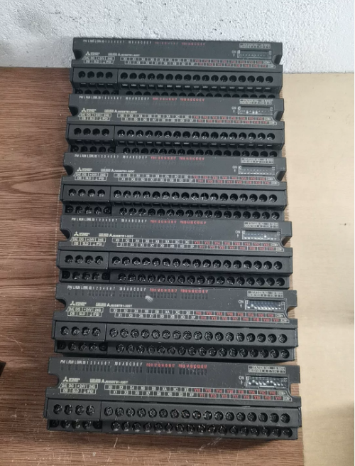

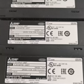
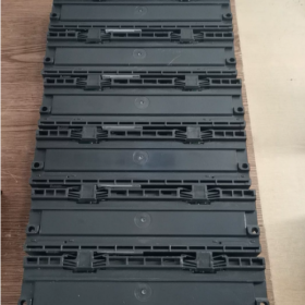
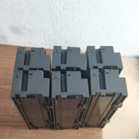
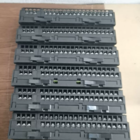
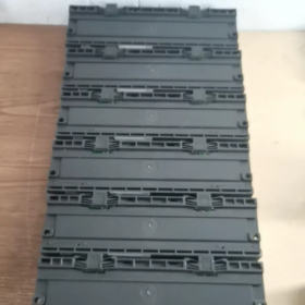
- 모델 정의 & 제품 포지셔닝
AJ65SBTB1-32DT: CC-Link용 소형 나사 단자대형 리모트 혼합 I/O 모듈
AJ65SB: CC-링크 리모트 I/O 시리즈
결핵1: 통합 나사 터미널 블록 (손가락 터치 보호형)
32: 총 32 I/O 포인트 (16 입력 + 16 출력)
디: DC24V 입력; 티: 싱크 트랜지스터 출력
점유 1 CC-Link 국번, 다중 스테이션 할당이 필요하지 않습니다.. Q/L/R 시리즈 CC-Link 마스터 스테이션과 호환 가능 (예를 들어, QJ61BT11N)
- 핵심 전기 사양
2.1 입력 섹션 (16-DC24V 포지티브 커먼 / 싱크 입력)
| 목 | 사양 |
| 포인트 수 | 16 전철기 (X0~X15) |
| 정격전압 | DC24V, 허용범위 19.2~26.4V (리플 ≤5%) |
| 포인트당 입력 전류 | 대략. 7엄마 |
| ON 임계값 | ≥14V / ≥3.5mA |
| OFF 임계값 | 6V 이하 / 1.7mA 이하 |
| 응답 시간 (끄기 ← 켜기) | 1.5ms 이하 |
| 격리 | 광커플러 절연 |
| 배선 방법 | 양극 공통 단자 (+24V에 연결된 COM, 입력 단자에 연결된 센서 음극선) |
2.2 출력 섹션 (16-포인트 싱크 트랜지스터 출력)
| 목 | 사양 |
| 포인트 수 | 16 전철기 (Y0~Y15) |
| 부하 전압 | DC19.2~26.4V |
| 포인트당 최대 전류 | 0.5A/포인트; COM당 총 전류: 3.6에이 |
| 돌입 전류 | 1A 이하 (지속 시간 ≤10ms) |
| OFF 상태 누설 전류 | 0.25mA 이하 |
| ON 상태 전압 강하 | 0.3V 이하 (0.5A 부하에서) |
| 응답 시간 | 0.5ms 이하 |
| 출력 논리 (싱크대) | 부하 음극을 출력 단자에 연결합니다.; 부하 양극을 외부 +24V에 연결 |
2.3 모듈 전원 공급 장치
공급 전압: DC20.4~26.4V
전체 전력 소비: 60mA 이하 (모든 I/O 포인트가 동시에 ON으로 전환됨)
- 기계 & 환경 매개변수
- 전체 치수: W179mm × H50mm × D40mm
- 무게: 0.25kg
- 터미널: M3 나사; 7-핀 통신 & 전원 분할 터미널 + 34-핀 I/O 터미널 블록
- 보호 등급: IP2X (손가락 감전 보호 기능이 있는 단자; 공작기계에 직접 장착 가능)
- 작동 온도: 0~55°C; 보관 온도: -20~75°C
- 습기: 10~90%RH, 결로가 없을 것
- 내전압: AC500V용 1 외부 DC 단자와 접지 간 분; 절연 저항 ≥10MΩ (500VDC에서 테스트됨)
- 주요 CC-Link 네트워크 배선 지침
- 버스 토폴로지: 데이지 체인 배선; 120Ω 종단 저항은 버스 양쪽 끝에 장착되어야 합니다.
- 통신케이블: 전용 CC-Link 실드 트위스트 페어 케이블
- 최대 버스 길이: 1.2킬로미터 (10Mbps 고속 모드)
- 역 주소: 모듈 측의 DIP 스위치를 통해 설정 (역 번호. 1~64)
- 터미널 정의: DA/DB 통신선, DG 쉴드 접지, 24V 모듈 전원 공급 장치, FG 프레임 보호 접지
- 시리즈 모델 차별화 (DT / DT1 / DT2)
AJ65SBTB1-32DT: 표준 모델; 7mA 입력 전류, COM당 최대 3.6A 총 출력 전류
AJ65SBTB1-32DT1: 저전류 입력 (5엄마), 2선식 근접 센서에 적합
AJ65SBTB1-32DT2: 개선된 응답 모델; 출력 COM에 대한 그룹화된 전류 제한, 향상된 간섭 방지 성능
- 일반적인 애플리케이션 시나리오
- 생산 라인을 위한 분산 현장 신호 수집, 포장 기계 및 사출 성형 기계
- 공작기계 근처에 장착된 센서 및 솔레노이드 밸브의 원격 제어
- 캐비닛 내부 배선을 줄이기 위해 대규모 생산 라인을 위한 CC-Link 슬레이브 스테이션 확장
- 물류 분류 및 컨베이어 라인을 위한 디지털 원격 I/O 슬레이브 스테이션
- 배선 & 설치 금지
- 모든 입력 COM 단자는 +24V에 균일하게 연결되어야 합니다.; 별도의 전원 공급 장치에서 접지 전위를 혼합하는 것은 금지됩니다.
- 트랜지스터 출력은 AC 부하를 직접 구동할 수 없습니다.; 외부 릴레이는 필수입니다
- 유도 부하 전체에 환류 다이오드를 병렬로 장착 (솔레노이드 밸브) 트랜지스터 고장을 방지하기 위해
- CC-Link 버스 실드층 단일점 접지; 양쪽 끝 접지 금지
- 권장 단자 와이어 게이지: AWG14~16; 나사 조임 토크: 0.8~1.0N·m
설치 완료 & AJ65SBTB1-32DT MITSUBISHI CC-Link 리모트 I/O 모듈 사용 설명서
- 하드웨어 구조 설명 (모듈 전면 패널)
1.1 LED 상태 표시기
| LED 라벨 | 정상상태 | 결함 표시 |
| 비밀번호 | 계속 켜져 있음 | DC24V 모듈 전원 정상; 꺼짐 = 전원 공급 장치 없음 |
| 달리다 | 계속 켜져 있음 | CC-Link 통신 정상; OFF = 통신 중단 |
| 오류 | 끄다 | 통신 정상; 계속 켜져 있음 / 깜박임 = 오류가 감지됨 |
| X0~XF / Y0~YF | 해당 LED가 켜집니다. | 각 입력/출력 채널 활성화 |
1.2 DIP 스위치 뱅크 (2 여러 떼)
역 번호. 스위치: 십자리 (40/20/10), 단위 자리 (8/4/2/1). 고유 국번 1~64를 설정하기 위한 합산값
통신 속도 스위치 (속도): 3-위치 스위치 (4/2/1) CC-Link 버스 전송 속도를 구성하려면
1.2 터미널 블록 분할 레이아웃
① 7핀 버스 터미널: 그리고, DB, DG, 24V+, 0다섯-, FG (의사소통 + 모듈 전원 공급 장치)
② 34핀 I/O 단자: X0~X15 입력, Y0~Y15 출력, 입력 COM, 출력 COM
1.3 DIN 레일 래치
하단의 스프링 래치, 표준 TH35 DIN 레일과 호환 가능
- 기계적 설치 절차
2.1 설치 환경 요구사항
작동 온도: 0~55°C; 직사광선을 피하세요, 먼지, 오일미스트, 응축 및 심한 진동 구역
방열 공간: 모듈 위와 아래에 ≥10mm 간격 확보; 발열 접촉기나 변압기 가까이에 장착하지 마십시오.
장착 방향: 수평 DIN 레일 장착 선호; 수직 장착에는 물 축적으로 인한 단락을 방지하기 위해 단자가 아래쪽을 향해야 합니다.
2.2 DIN 레일 장착 단계
- 상단 모듈 슬롯을 TH35 DIN 레일의 상단 가장자리에 겁니다.
- 걸쇠가 딸깍 소리를 내며 잠긴 위치에 들어갈 때까지 모듈 하단을 아래쪽으로 누릅니다.
- 제거: 하단 걸쇠를 아래로 누릅니다., 모듈을 위로 들어 올려 분리하세요.
2.3 나사 장착 (DIN 레일 없음)
M4 나사와 평와셔를 사용하여 모듈 양쪽의 장착 구멍을 고정합니다.; 조임 토크: 0.8~1.1N·m
- DIP 스위치 하드웨어 구성 (전원을 끈 상태에서 수행! 전원이 공급되는 상태에서 스위치를 수정하면 ERR 경보가 발생합니다.)
3.1 국번 설정 (중요 - 전체 네트워크에 고유함, 중복은 허용되지 않습니다)
규칙: 십 자리 값 (40/20/10) + 단위 자리 값 (8/4/2/1) = 총국번호 (범위: 1~64)
예:
1번 역: 단위 숫자만 1 켜짐, 그 외 모두 꺼짐
12번 역: 십자리 10 에 + 단위 자리 2 에 (10+2=12)
32번 역: 십자리 20 & 10 에 + 단위 자리 2 에 (20+10+2=32)
> 경고: 하나의 CC-Link 버스에 중복된 국번이 있으면 모든 국의 전체 통신 장애가 발생합니다.
3.2 통신속도 설정 (QJ61BT11N 마스터 스테이션 속도와 완전히 일치해야 합니다.)
| 속도 스위치 (4/2/1) | 버스 전송 속도 | 최대 버스 길이 |
| 꺼짐 꺼짐 꺼짐 | 156kbps | 1200중 |
| 꺼짐 꺼짐 켜짐 | 625kbps | 900중 |
| 꺼짐 켜짐 꺼짐 | 2.5Mbps | 400중 |
| 꺼짐 켜짐 켜짐 | 5Mbps | 200중 |
| 켜짐 꺼짐 꺼짐 | 10Mbps | 100중 |
- 단계별 터미널 배선 가이드 (전원을 켜기 전에 모든 배선을 완료하십시오.; 배선 중 전원 끄기)
부분 1: CC-링크 버스 & 모듈 전원 공급 장치 (7-핀 터미널)
터미널 순서: DA → DB → DG → 24V+ → 0V→ FG
- 통신 케이블 (전용 CC-링크 차폐 트위스트 페어)
그리고 & DB: 모든 원격 모듈을 직렬로 데이지 체인 방식으로 연결; 버스의 첫 번째 모듈과 마지막 모듈의 DA/DB에 120Ω 종단 저항을 연결합니다.
DG: 통신 쉴드 연결; 한쪽 버스 끝에서만 단일 지점 접지, 이중 접지 금지
- 모듈 작동 전원 공급 장치
24다섯 & 0다섯: 모듈 메인보드용 DC24V 전원 공급 장치; 작동 범위 19.2~26.4V
FG: 모듈 보호 접지, 캐비닛 PE 접지에 연결
> 배선사양: 380V 전원 케이블에서 멀리 떨어진 곳에 CC-Link 케이블 배선; ≥30cm 평행 분리 유지; 교차 배선은 수직이어야 합니다
부분 2: 16-포인트 DC24V 싱크 입력 (X0~X15)
- 모든 입력 COM 터미널은 DC24V 양극에 균일하게 연결됩니다. (+)
- 2선식 센서의 양극선을 24V에 연결합니다., X0~X15 입력 단자에 음극선 연결
- 독립 전원 공급 장치가 없는 센서: 24V+를 COM에 직접 연결, 센서 음극선을 X 단자에 연결
입력 논리: X 단자에 0V 신호가 인가될 때, 해당 X LED가 켜지고 PLC 입력이 ON됩니다.
부분 3: 16-포인트 싱크 트랜지스터 출력 (Y0~Y15)
- 모든 출력 COM 터미널은 DC24V 양극에 균일하게 연결됩니다. (+)
- 솔레노이드 밸브의 양극선을 연결합니다. / DC24V+에 대한 표시 부하, Y0~Y15 출력 단자에 음극선 연결
- 유도 부하 (솔레노이드 코일): 트랜지스터 고장을 방지하기 위해 음극이 +24V에, 양극이 Y 단자에 병렬 프리휠링 다이오드를 설치합니다.
- 전류 제한: 단일 포인트당 최대 0.5A; 모두에 대한 총 전류 16 포인트 ≤3.6A. 고전류 부하용 중간 계전기 설치
케이블 사양 & 조임 토크
와이어 단면: 0.3~1.25mm²; M3 단자 나사 토크: 0.8~1.0N·m. 실이 벗겨지는 것을 방지하려면 너무 세게 조이지 마십시오.
- PLC 소프트웨어 구성 (GX 웍스2 / GX 웍스3; Q 시리즈 마스터 스테이션 QJ61BT11N 예시)
단계 1: CC-Link 네트워크 매개변수에 액세스
프로젝트 탐색 트리 → [매개변수] → [네트워크 매개변수] → [CC-링크]; 마스터 스테이션 모듈의 슬롯 위치 선택
단계 2: 기본 버스 매개변수 일치
- 방법: 원격 네트워크 Ver.1 모드
- 전송 속도: 원격 모듈의 DIP 스위치 속도 설정과 완전히 일치
- 총 연결 스테이션: 버스에서 사용되는 최대 국번을 입력하세요. (예를 들어, 입력 10 가장 높은 스테이션인 경우 No. ~이다 10)
단계 3: AJ65SBTB1-32DT 슬레이브 스테이션 추가 (리모트 I/O 스테이션)
- 역 번호: 하드웨어 DIP 스위치를 통해 설정된 스테이션 번호를 입력하세요. (1, 2, 3…)
- 스테이션 유형: 리모트 I/O 스테이션
- 점유국 수: 1 (이 모듈은 영구적으로 점유됩니다. 1 역 주소)
- 자동 할당된 원격 XY 주소: 16 X 주소를 입력하세요, 16 Y 주소 출력 (32 연속 포인트 합계)
단계 4: PLC에 매개변수 쓰기 및 통신을 위한 전원 켜기
- 매개변수 저장 및 온라인으로 PLC CPU에 쓰기
- PLC와 원격 모듈의 전원을 동시에 켜세요; 모듈의 지속적인 RUN LED는 정상적인 통신을 확인합니다.
- 깜박이는 ERR LED: 역 번호 확인, 버스 속도, 종단 저항기 및 DA/DB 와이어 극성
- 전원 켜기 시운전 & 작동 방법
6.1 정상적인 통신 확인
PW 계속 ON + 계속 켜져 있음 + ERR OFF → 버스 통신 링크가 성공적으로 구축되었습니다.
6.2 입력 신호 테스트
- 트리거 필드 푸시버튼 / 광전 센서; 모듈의 해당 X LED가 켜집니다.
- GX Works 소프트웨어를 통한 온라인 모니터: 해당 원격 X 레지스터가 ON 상태로 전환됩니다.
6.3 출력 제어 테스트
- PLC 프로그램에서 해당 원격 Y 레지스터를 강제로 ON합니다.
- 모듈의 해당 Y LED가 켜지고 연결된 부하가 작동합니다.
6.4 일일 프로그램 사용량
자동 할당된 원격 X/Y 주소를 직접 읽기/쓰기; 전용 통신 서브루틴 없이 로컬 I/O와 동일한 프로그래밍 논리
예: 국번1 AJ65SBTB1-32DT 리모트 주소: X100~X10F (입력), Y100~Y10F (출력)
- 일반적인 오류 문제 해결 (LED 이상 & 대책)
- 비밀번호 LED 꺼짐: 7핀 터미널의 느슨한 24V/0V 배선, 전원 공급 장치 고장, 단자 단락
- 흘러넘치다 + ERR 계속 켜져 있음
마스터 스테이션 버스 속도와 모듈 DIP 스위치 속도 불일치
DA/DB 통신선이 뒤바뀌거나 파손됨
버스 끝 또는 이중 끝 접지에 120Ω 종단 저항 누락
- 정기적인 ERR 깜박임: 전원이 켜진 상태에서 수정된 DIP 스위치 → 전원 끄기 모듈, 스위치를 재설정한 다음 다시 전원을 켜세요.
- 입력 LED가 켜지지 않음: COM 터미널이 +24V에서 분리됨, 끊어진 센서 와이어, DC24V 공급 전압이 부족함
- 출력 작동 없음: 출력 COM에 +24V 공급 없음, 부하 단락, 단일 채널 과전류 (0.5A 초과) 보호 트리거
- 필수 설치 & 작업 금지
- 전원이 공급되는 동안 모듈을 연결/분리하거나 DIP 스위치를 조정하는 것은 엄격히 금지됩니다.
- CC-Link 버스 차폐층 접지는 단일 종단으로 제한됩니다.; 이중 접지 금지
- 트랜지스터 출력은 AC220V 부하를 직접 구동할 수 없습니다.; 중간 릴레이는 필수입니다
- 전위차로 인한 잘못된 트리거를 방지하려면 입력 및 출력 COM 터미널을 별도의 전원 공급 시스템에 연결하지 마십시오.
- 인버터, 용접기 등 전자파 간섭이 심한 장비 옆에 모듈을 설치하지 마십시오.
- 120Ω 종단 저항은 버스 양쪽 끝에 장착되어야 합니다., 장거리 통신에 필수





NH42-63-318x560.png "CHINT PC형 자동절환스위치 (ATS)NH42-63/4SZ")



