 접촉기,회로 차단기,감지기,인코더,PLC,변환기

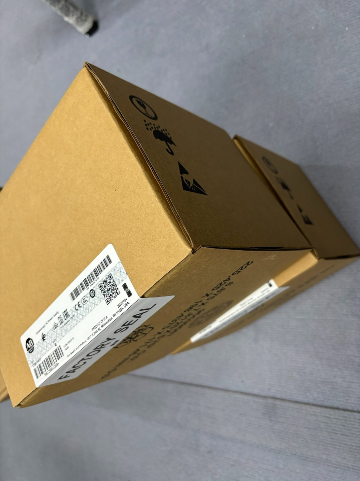

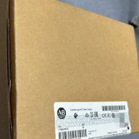
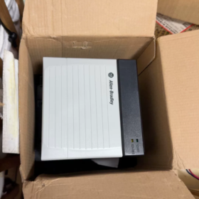
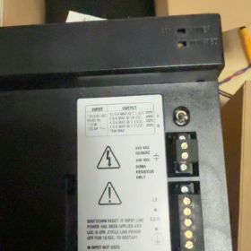
1756-PA75
1756: ControlLogix 5000 Chassis Series
아빠: AC Input Backplane 전원공급장치
75: Maximum backplane output power 75W
파생 모델:
1756-PA75K: PCB with conformal coating (for corrosive and humid environments)
1756-PA75R: Redundancy-specific power supply. Cannot be directly used interchangeably with PA75. Requires 1756-PSCA2 Adapter + 1756-CPR2 Cable
> ⚠️ Critical Note: The standard 1756-PA75 does not support native redundancy! PA75R kit must be selected for redundant configurations.
- 핵심 전기 사양
입력 등급
입력 전압: 85~265 VAC (wide-range, compatible with 120V/240V systems)
빈도: 47~63 Hz
Maximum input apparent power: 100 버지니아
Maximum inrush current: 20 에이
Multi-rail DC Backplane Output (75W full load at 0~60℃)
| Output Rail | Maximum Current |
| 5.1 DC에서 | 13.0 에이 |
| 3.3 DC에서 | 4.0 에이 |
| 1.2 DC에서 | 1.5 에이 |
| 24 DC에서 (Auxiliary Backplane) | 2.8 에이 |
기계 & 환경 사양
폼 팩터: Standard single-slot 1756 전원 모듈, installed in the leftmost slot of ControlLogix chassis
치수: 140 × 112 × 145 mm
무게: 대략. 1.45 kg
작동 온도: 0~+60 ℃; 보관 온도: -40~+85 ℃
습기: 5%~95%, 비응축
격리: Reinforced insulation between input and backplane, rated for continuous 250V withstand
인증: UL, CE, CCC, CSA, 등.
보호 기능: 과전압, 과전류, 온도 이상, 단락 보호
- Front Panel Indicators
- 좋아요 (녹색)
계속 켜져 있음: Power supply healthy
끄다 / 섬광: Fault detected
- FAULT (빨간색)
조명: 초과 적재, 온도 이상, internal failure
- 경보 (Relay Dry Contact)
Passive alarm contact, can be wired to external alarm circuits.
- Comparison with Similar Models
| 모델 | 입력 유형 | 전력 등급 | Redundancy Capability | 일반적인 애플리케이션 시나리오 |
| 1756-PA75 | 85–265V AC | 75여 | Standard standalone unit, not directly redundant | General single-chassis systems |
| 1756-PA75K | 85–265V AC | 75여 | 독립형, conformal coated PCB | 습함, 무미 건조한, corrosive enclosures |
| 1756-PA75R | 85–265V AC | 75여 | Supports dual-unit redundancy (requires PSCA2+CPR2) | Critical production lines requiring zero downtime |
| 1756-PB75 | 18–32V DC | 75여 | Standalone DC input power supply | Sites with only 24VDC available |
| 1756-PA72 | 85–265V AC | 72여 | Legacy model, lower load capacity | Replacement for obsolete equipment |
- Key Selection Rules & Pitfall Avoidance
- Do not judge load solely by total 75W power rating!
Calculate current consumption of all modules in the chassis for each voltage rail (5.1V/3.3V/1.2V). Exceeding the limit on any single rail will trigger FAULT shutdown.
- 설치 위치: Must be mounted in the first leftmost slot of the chassis; cannot be placed in middle or right slots.
- Thermal management: Avoid long-term enclosure temperature above 55℃; derate power in high-temperature environments.
- Hot Swapping: Hot-swap capable. It is recommended to stop controller logic before swapping to prevent transient interference to communication modules.
- Redundancy Misconception: Two standard PA75 units cannot be paralleled directly to achieve redundancy. PA75R redundancy kit is mandatory.
- 일반적인 문제 해결
- FAULT red light ON, OK light OFF
Step1: Remove all modules from chassis, leave only power supply and power on.
If fault persists under no load → Power supply failure.
If normal under no load → Short circuit or overload from chassis modules.
- Circuit breaker trips immediately after power-up
The unit has high inrush current on startup; select D-curve MCB for upstream protection. Check L/N/PE wiring for short circuits.
- Intermittent FAULT alarm after continuous operation
Insufficient cabinet ventilation, dust accumulation; overtemperature protection triggered due to long-term near-full-load operation.
- Typical Industry Applications
Chemical industry, 수처리, automotive production lines, 야금, 자재 취급, 기름 & 가스, large building DCS/PLC systems (power supply for ControlLogix L7x/L8x controller chassis).
Overload Capability of 1756-PA75 (Based on Rockwell Official Document 1756-TD005)
- Critical Premise
75W = Continuous rated output power (0~60℃ ambient temperature), NOT peak power. Continuous overload operation is not officially permitted.
The power supply adopts independent multi-rail current limiting protection.
Protection triggers once any single rail exceeds current limit, regardless of total power consumption.
Continuous rated current hard limits for each backplane rail:
| Output Rail | Continuous Rated Current |
| 5.1 VDC | 13.0 에이 |
| 3.3 VDC | 4.0 에이 |
| 1.2 VDC | 1.5 에이 |
| 백플레인 24 VDC Auxiliary | 2.8 에이 |
- Overload Classification & Actual Endurance
2.1 Continuous Overload (Long-term operation above rating)
❌ Not supported or approved by Rockwell
If any rail runs continuously above rated current, or total power exceeds 75W:
- Internal temperature rises steadily;
- FAULT indicator illuminates and output shuts down for protection once threshold is reached;
- Long-term marginal overload accelerates aging of internal capacitors and power semiconductors, shortens service life and voids warranty.
> Field Experience: Continuous load between 70~75W is already the design ceiling. Long-term operation at this level is not recommended. Operation above 75W is strictly prohibited.
2.2 Transient Short-duration Overload (Module power-on inrush, pulse loads)
1756-PA75 can withstand limited short-term peak loads.
Rockwell does not publish precise millisecond overload curves (no specified duration for 120%/150% 초과 적재).
Summary of official design principles plus extensive field experience:
Capable of sustaining hundreds-of-millisecond transient inrush current (simultaneous power-up surge of chassis modules);
Transient peak current may briefly exceed rated value, but cannot be sustained steadily;
System load design shall never rely on transient overload capability. Load calculation must adopt continuous rated parameters.
2.3 보호 메커니즘 & Action Logic
- Electronic Current Limiting + Hiccup Protection Mode
초과 적재 / Short-circuit → Output current clamped → Voltage drop → Temporary shutdown → Automatic retry (hiccup cycling).
- Front panel FAULT red indicator steady ON, OK indicator OFF
- Alarm relay contact actuates
- Automatic recovery is achievable in most cases after overload load is removed. Severe sustained overload may require power cycle to recover.
2.4 Temperature Degradation of Overload Tolerance
Rated 75W output condition: Ambient Temperature 0~60℃
Cabinet temperature >50℃: Recommend 5%~10% power derating
Long-term cabinet temperature >55℃: Even if total power ≤75W, thermal accumulation easily triggers overtemperature overload protection.
주변 온도 >60℃: Rated output performance is no longer guaranteed; overload endurance drops significantly.
- Two Common Critical Misunderstandings
오해 1: Parallel two standard 1756-PA75 to increase overload capacity
❌ Absolutely Not Allowed!
Standard PA75 has no current sharing circuit. Parallel connection on backplane is forbidden.
It cannot share load, expand capacity or realize redundancy. Parallel setup will create circulating current and lead to single-point burnout.
For redundancy or capacity expansion: Adopt 1756-PA75R redundancy power supply kit (with 1756-PSCA2 & 1756-CPR2).
오해 2: System will not overload as long as total power <75여
❌ Independent current limiting for each voltage rail!
예: Total power 68W, but 5.1V rail current reaches 13.5A → Immediate overload shutdown.
✅ Standard load verification method: Calculate total power AND current consumption of every DC rail.
- Load Design & 선택 권장 사항
- Reserve 15%~25% design margin for steady-state operating load
- Sum up backplane power consumption of all modules, tabulate current demand for 5.1V/3.3V/1.2V/24V rails separately
- Further increase margin if chassis contains numerous high-inrush I/O modules (릴레이 출력, 고속 카운터)
- If intermittent FAULT flashes occur during operation, priority inspection items: Single rail current close to limit, inadequate cabinet heat dissipation.
- Brief Overload Performance Comparison between PA75 and PA75R
PA75 (기준): Standalone unit, overload protection logic as stated above
PA75R (Redundancy model): Single unit rated power also 75W.
In redundant configuration, one unit must temporarily bear full load after the other fails. Transient load margin is optimized in firmware, yet continuous load cannot exceed single-unit 75W specification.
Complete Model List for 1756-PA75 Family (75W Power Class)
> Model Nomenclature Guide
아빠: AC 입력; PB: 24V DC Input; PC/PH: Special wide-range DC Input
75: Rated backplane output power 75W
케이: PCB conformal coating (resist humidity & 부식성 가스)
아르 자형: Redundancy dedicated power supply (cannot be used as standalone regular unit)
XT: Extended temperature heavy-duty industrial version
- AC Input 75W Series (PA75 Family)
- 1756-PA75
Standard AC power supply, 85~265VAC, 75여, most widely used for general applications.
- 1756-PA75K
Conformal coated variant. Electrical performance identical to PA75. Suitable for chemical, 습한, dusty and corrosive enclosures.
- 1756-PA75R
Redundancy-dedicated AC power supply, equipped with internal hardware for redundant communication. Must be matched with: 1756-PSCA2 (Redundancy Adapter) + 1756-CPR2 Cable.
⚠️ Forbidden to install directly into chassis and operate as standalone unit!
- 1756-PA75RK
Redundancy type + conformal coated PCB. Selected for redundant systems deployed in corrosive environments.
- 75W DC Input Equivalent Models (For cross-reference replacement)
- 1756-PB75: 18~32VDC (24V DC 공급) standard power supply
- 1756-PB75K: 24V DC input + 컨포멀 코팅
- 1756-PB75R: 24V DC redundancy power supply
- 1756-PB75RK: 24V DC redundancy + 컨포멀 코팅
- 1756-PC75: 48V DC dedicated input power supply
- 1756-PH75: Wide-range DC 48~125VDC (지서, DC panel applications)
- 1756-PH75K: Wide-range DC input + 컨포멀 코팅
- Other Power Rating Power Supplies for the Same Chassis (Selection Distinction)
3.1 Legacy 72W Series (Lower 5V rail current, 새로운 프로젝트에는 권장되지 않습니다)
1756-PA72 (교류), 1756-PA72K
1756-PB72 (DC), 1756-PB72K
3.2 Low-power single-slot models (Same physical slot width, 낮은 전력)
1756-PA50 / PB50: 50여
1756-PA30XT / PB30XT: 30여, XT extended temperature series
3.3 XT Extended Temperature Heavy-duty Series (-20℃~70℃ operating range)
1756-PAXT (AC extended temp), 1756-PBXT (DC extended temp)
1756-PAXTR / PBXTR: Redundancy power supply for XT series
- Critical Selection Pitfall Notes
- 1756-PA75 ≠ PA75R
Two standard PA75 units cannot be paralleled for redundancy. PA75R kit is required for redundant systems.
- K suffix only indicates conformal coating. Electrical parameters and backplane load capacity are fully identical to non-K models; direct interchange is supported.
- Mechanical dimension: All standard 75W power supplies (PA75/PA75K/PB75 etc.) are single-slot form factor, mounted on leftmost chassis slot.
PA75R redundancy power supply cannot directly power chassis without matching redundancy adapter.
- Hardware revision suffix /A /B: Iterative hardware upgrades. Units with same catalog number (A/B revisions) are electrically compatible and directly interchangeable.
Quick Selection Table
| 모델 | 입력 유형 | 컨포멀 코팅 | 이중화 지원 | 일반적인 애플리케이션 시나리오 |
| 1756-PA75 | 85~265VAC | ❌ No | 독립형 | Standard control cabinets in general workshops |
| 1756-PA75K | 85~265VAC | ✅ Yes | 독립형 | High-humidity, coastal & chemical corrosive environments |
| 1756-PA75R | 85~265VAC | ❌ No | 많은 (액세서리가 필요합니다) | High-reliability production lines intolerant to shutdown |
| 1756-PA75RK | 85~265VAC | ✅ Yes | 많은 (액세서리가 필요합니다) | High-reliability systems in corrosive atmosphere |





NH42-63-318x560.png "CHINT PC형 자동절환스위치 (ATS)NH42-63/4SZ")



