 접촉기,회로 차단기,감지기,인코더,PLC,변환기

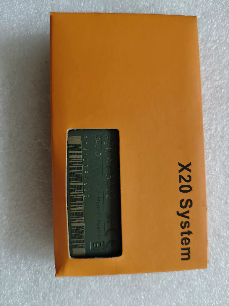

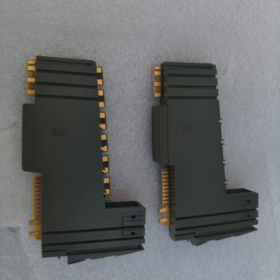
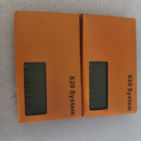
X20: X20 I/O system series
에: Analog Temperature 입력
6402: 6channel thermocouple module; X20cAT6402 is the conformalcoated version (응축 & corrosivegas resistant)
일반 설명
X20AT6402 is a 6channel thermocouple temperature acquisition module for X20 PLC distributed I/O. It features integrated terminal coldjunction compensation, supporting J/K/N/S/B/R thermocouple types. SigmaDelta 16bit ADC; it can output engineering temperature values or raw millivolt readings.
⚠️Note: No galvanic isolation between channels; isolation exists between bus side and I/O side.
Mandatory accessories: X20TB12 (12pin terminal block), X20BM11 bus base. Terminals are NOT supplied with the module.
주요 기술 사양
| 목 | 사양 |
| 채널 | 6 thermocouple inputs |
| Supported thermocouples | 제이, 케이, N, 에스, 비, 아르 자형 (EN60584) |
| ADC | Sigma‑Delta, 16-조금 |
| Cold‑junction compensation | Integrated terminal‑based compensation; no external PT1000 required |
| Filter time | 구성 가능: 1 ms ~ 66.7 ms |
| Input range | ±70 mV (thermocouple mV signal) |
| 해결 | 0.1 ℃ / 0.01 ℃ software selectable; raw value:1.0625 μV |
| Basic accuracy @25℃ | 제이: ±0.10%; K/N: ±0.11%; 에스: ±0.17% |
| Common‑mode voltage | ±15 V |
| 소비전력 | 버스: 0.01 여; I/O side: 0.91 여 |
| 작동 온도 | 수평 장착:0‑55 ℃; 수직 장착:0‑50 ℃; derate 0.5℃/100 m above 2000 m altitude |
| 보호 등급 | IP20, cabinet‑mount only |
| 보관온도 | -40 ~ +85 ℃ |
| 진단 | Module status, channel wire‑break detection, LED status indicators |
| Output format | INT; engineering temperature or raw mV values selectable |
배선 참고 사항
- Each thermocouple channel uses 2 터미널 (TC+, TC). Six channels occupy 12 다리, matching X20TB12 terminal block.
- Do not reverse thermocouple polarity; always use matched thermocouple extension wires.
- No galvanic isolation between channels. For multipoint measurement, control reference potential difference to avoid commonmode interference.
- Coldjunction compensation uses onboard terminal temperature measurement; keep terminal block away from heatgenerating components.
소프트웨어 구성 (Automation Studio)
- Add hardware `X20AT6402` in hardware tree.
- Independently set sensor type (J/K/N/S/B/R) for each channel.
- Configure filter time; select output: engineering temperature ℃ or raw millivolt value.
- Enable wirebreak diagnosis.
Alternative X20Series Selection
| 모델 | 채널 | 특징 |
| X20AT2402 | 2 | Economical 2‑channel thermocouple module, same sensor support |
| X20ATA492 | 2 | Galvanic channel‑to‑channel isolation, requires external PT1000 cold‑junction sensor at terminals |
| X20cAT6402 | 6 | Conformal coated; for high‑humidity / corrosive‑gas cabinet environments |
일반적인 응용
Heattreatment furnaces, 오븐, 사출 성형 기계, 압출기, 가마, multipoint temperature acquisition for energyrelated equipment.
Secondhand Module Inspection Checklist
- 육안검사: No terminal burn marks; backplane gold contacts intact.
- Poweron test: RUN LED normal; no module fault alarms.
- 기능 테스트: Connect known Ktype thermocouple; compare readings against reference thermometer across all channels.
- Verify hardware revision; distinguish standard version vs conformalcoated `c` variant.
비&아르 자형 X20AT6402 Installation Manual (Practical English Version)
Official full document: X20 System User´s Manual, chapter 9.32.7 for X20AT6402. Download from B&R official website after login. X20cAT6402 shares identical hardware mechanics with conformal coating applied.
This is slicestyle X20 I/O. Mandatory parts: X20BM11 bus base + X20TB12 spring terminal block; terminals are not included with module.
1 안전 전제조건
- Install only inside electrical cabinet; protection rating IP20. Not for outdoor deployment.
- Disconnect 24 V DC power for installation / removal / 배선. Hotswap is supported, but perform wiring with power removed.
- ESD 보호: Wear antistatic wrist strap. Do not touch goldplated backplane contacts directly by hand.
- 환경 조건
| 목 | 매개변수 |
| 작동 온도 (horizontal mount) | 0~+55℃ |
| 작동 온도 (vertical mount) | 0~+50℃ |
| 고도 | 0‑2000 m unrestricted; >2000 m, derate ambient temperature by 0.5℃ per 100 m elevation |
| 상대습도 | 5‑95%, 비응축 |
| 저장 / 운송 온도 | -40~+85℃ |
2 기계적인 설치 (DINrail TS35 EN60715)
2.1 Mandatory Clearance for Heat Dissipation
Minimum 10 mm clearance left and right of each module.
수평 장착: ≥35 mm free ventilation space above and below module.
수직 장착: CPU must be placed below all I/O modules.
Tilt angle must not exceed 120°.
2.2 Assembly Procedure
- Clip X20BM11 bus base onto DINrail, press down to lock firmly.
- Snap X20 sliceI/O modules sequentially onto base, keep modules tightly adjacent.
- Insert X20AT6402 downwards into X20BM11 base until audible click; confirm both side latches fully engaged.
- Fit X20TB12 (12pin spring terminal block) onto front face of module. Terminals can be detached for offline prewiring.
Removal Procedure
- Remove power supply.
- Press triangular release latch on top of module; lift module upward to separate from bus base.
- Pull terminal block straight outward.
2.3 Mandatory Hardware BillofMaterials
| 부품 번호. | 설명 | 목적 |
| X20AT6402 | 6‑channel thermocouple input module | Signal acquisition unit |
| X20BM11 | Bus base | DIN 레일 장착, back‑plane bus, 24 V power distribution |
| X20TB12 | 12‑pin spring terminal block | Thermocouple field wiring |
3 전기 배선
3.1 Bus Power Supply
X20BM11 receives 24 VDC to supply backplane bus and X20AT6402 module.
소비전력: Bus side 0.01 W; I/O side 0.91 W.
3.2 Thermocouple Field Wiring (X20TB12 terminals)
Six thermocouple channels, each channel uses TCx+, TCx differential pair; 총 12 다리.
Always use matched thermocouple extension wire; strictly observe polarity.
⚠️Critical: No interchannel isolation; bustoI/O isolation present. Keep commonmode voltage ≤±15 V to prevent measurement drift for multisensor systems.
Coldjunction compensation: Onboard terminal temperature measurement. Locate terminal block away from contactors, power supplies and other heatgenerating devices.
Cabling practice: Run thermocouple lowlevel mV signal cables separately from power cables; avoid parallel bundling. Shield cable singleend grounding: connect shield to cabinet ground; leave sensorside shield floating.
Spring terminal wiring: Conductor crosssection 0.081.5 mm². Press spring tab with flatblade screwdriver, insert wire, release to lock conductor.
Recommended practice: Tie thermocouple negative terminals to module reference ground to suppress rippleinduced measurement error.
3.3 터미널 할당
| 채널 | Positive | Negative |
| TC1 | 1 | 2 |
| TC2 | 3 | 4 |
| TC3 | 5 | 6 |
| TC4 | 7 | 8 |
| TC5 | 9 | 10 |
| TC6 | 11 | 12 |
4 LED 상태 표시기
Module frontpanel LED definition:
- RUN Green: Steadyon = module healthy running; blinking = no valid configuration; off = no power / 하드웨어 결함.
- ERR Red: On = module fault; blinking = channel wirebreak / sensor failure.
Wirebreak detection: Diagnostics enabled in software; ERR LED blinks on thermocouple opencircuit, PLC receives fault code.
5 Automation Studio Hardware Configuration
- Insert hardware `X20AT6402` in hardware tree; verify firmware compatibility.
- Perchannel parameters:
센서 유형: 제이 / 케이 / N / 에스 / 비 / 아르 자형
Filter time:1 ms ~ 66.7 ms; set to 66.7 ms for 50 Hz mains noise suppression.
출력 모드: Engineering temperature ℃ / raw mV value.
해결:0.1℃ /0.01℃ selectable.
Enable wirebreak diagnosis.
- Download hardware configuration, restart X20 I/O bus.
- 확인: Connect known thermocouple; crosscheck temperature readings against reference thermometer.
6 시운전 & 문제 해결
| 징후 | Troubleshooting Guidance |
| ERR red LED permanently ON | Check 24 V supply; verify X20BM11 latch engagement; check firmware version; hardware damage |
| Temperature readings unstable / jittery | Reversed extension‑wire polarity; mixed routing with power cables; common‑mode voltage >±15 V; poor terminal contact; filter time too short |
| ‑273 ℃ reading for all channels | Diagnostics reports open‑circuit; inspect thermocouple cables and terminal block seating |
| Abnormality on single channel | 확인하다 +/- polarity; thermocouple sensor damage; loose terminal crimp |
7 유지 & Sparepart Replacement
- Hotswap capability: Poweroff swap is preferred; live module replacement allowed. No project redownload required when replacing with identical part number.
- Cabinet environment: Keep cabinet dustfree, avoid condensation.
- Distinguish standard X20AT6402 vs coated X20cAT6402; spareparts cannot be interchanged arbitrarily.
8 Official Document Access
- 비&R official website → Support → Document download, search partnumber `X20AT6402`;
- Available documents: 데이터시트, X20 System User Manual. 비&R user login required for PDF download.
X20AT6402 Faultcode Reference & ST Variable Mapping Example
1 Channel Diagnostic Status (2 status bits per channel)
Each thermocouple channel returns: Temperature value + channel status bits
| 2‑bit channel status | 설명 | Fault value (0.1℃ INT mode) | Recommended Action |
| 0 | Normal measurement | Actual temperature value | No action required |
| 1 | Input under‑range (below measurement span) | ‑32767 (0x8001) | Verify thermocouple type setting; input millivolt level too low |
| 10 | Input over‑range (above measurement span) | +32767 (0x7FFF) | Thermocouple exceeds measuring range; re‑check sensor selection |
| 11 | Open‑circuit / 단선 | +32767 (0x7FFF) | Broken thermocouple / extension wire; loose terminal connection |
Global module fault flag: `0x8000` = general module failure
LED Diagnostic Table
| 주도의 | 색상 | 상태 | 오류 설명 |
| 아르 자형(달리다) | 녹색 | 끄다 | No 24 V supply to module |
| 아르 자형(달리다) | 녹색 | Steady‑on | Normal RUN state |
| 아르 자형(달리다) | 녹색 | 깜박임 | Hardware configuration not downloaded, pre‑operational mode |
| 이자형(오류) | 빨간색 | 끄다 | No fault present |
| 이자형(오류) | 빨간색 | Steady‑on | Hardware fault / firmware mismatch |
| 이자형(오류) | 빨간색 | 깜박임 | At least one channel: wire‑break / over‑range / under‑range |
| CH1‑CH6 channel LED | 녹색 | Steady‑on | Channel measurement healthy |
| CH1‑CH6 channel LED | 녹색 | 깜박임 | Channel open‑circuit / range violation alarm |
2 ST StructuredText Variable Mapping (Automation Studio)
X20AT6402 has 6 채널. Each channel delivers INT temperature value + channel status byte.
Two resolution modes available: 0.1 ℃ (INT), 0.01 ℃ (DINT).
3 Comprehensive Field Troubleshooting List
- All channels read 32767
징후: All channels return `0x7FFF`, channelstatus =3 (opencircuit).
Checklist: X20TB12 fully seated; X20BM11 latches locked; 24 V supply voltage drop.
- Singlechannel returns 32767, other channels normal
Possible rootcauses: Broken thermocouple / extension wire; loose terminal crimp; reversed thermocouple polarity.
- Temperature reading jitter / drift
1) Filter time too short and mains interference present; set filter time to 66.7 ms for 50 Hz suppression.
2) Thermocouple extension wire runs parallel with power cables; separate cable routing; singleend shield grounding at cabinet.
3) Interchannel commonmode voltage >±15 V. No interchannel isolation; large referencepotential difference between multiple thermocouples.
- ERR LED solid red, RUN LED blinking green
Firmware version mismatch; hardware configuration mismatches physical hardware. Distinguish X20AT6402 vs X20cAT6402, do not crosscompile configuration.
- Fixed 273 ℃ reading
Typical opencircuit symptom when wirebreak diagnosis is enabled; inspect sensor wiring loop first.
4 Diagnostic Function Block Tip
Automation Studio standard library provides `X20DiagGetChannelState()` function block. It directly reads channel fault status without manual bitmask parsing.
Input hardwareID for X20AT6402: `161BA9`; function returns enumerated channelfault state.





NH42-63-318x560.png "CHINT PC형 자동절환스위치 (ATS)NH42-63/4SZ")



