 접촉기,회로 차단기,감지기,인코더,PLC,변환기

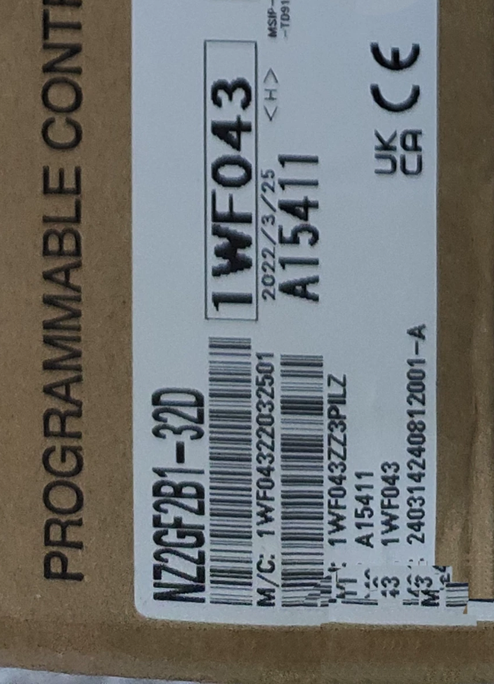

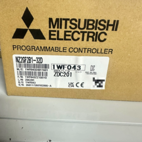
모델 코드 분석
| 암호 | 정의 |
| NZ | CC-Link IE Field Remote I/O Series |
| 2G | 2nd-Generation CC-Link IE Field Gigabit Fieldbus |
| 에프 | Digital I/O Remote Unit |
| 지하 1층 | Standard Terminal Block Type (Non-waterproof / Non-high-speed) |
| 32 | 총 32 I/O 포인트 |
| 디 | DC Digital Input Module |
제품 포지셔닝: Gigabit Ethernet CC-Link IE Field intelligent remote station module with 32-point DC24V digital inputs, compatible with Q/L/R/FX5U series PLC master stations.
- 핵심 전기 사양
2.1 입력사양
전철기: 32-포인트 DC24V 디지털 입력, all 32 points share one common COM terminal, compatible with both sink and source wiring (supports positive/negative common modes)
정격전압: DC24V (허용범위: 20.4~28.8V, 리플 ≤5%)
Single-point Input Current: Typical 6mA @ 24V, input resistance 3.8kΩ
ON 임계값: ≥15V / ≥4mA; OFF 임계값: 5V 이하 / ≤1.5mA
응답 시간 (8 software-selectable gears, default 10ms): 0/0.2/1/1.5/5/10/20/70ms
격리: 광커플러 절연; Withstand voltage AC510V for 1 분, insulation resistance ≥10MΩ (DC500V)
Simultaneous ON: 100% full-point simultaneous ON without voltage drop limitation
- Module Power & 의사소통
Unit Power Supply: DC24V, total power consumption ≤120mA (all points ON)
버스 종류: CC-Link IE Field 1000BASE-T Gigabit Ethernet
Network Ports: 듀얼 RJ45 (IN/OUT, daisy-chain topology). Cat5e or higher double-shielded STP straight-through cables are mandatory
스테이션 유형: Intelligent device station, 차지하다 1 logical station
Communication Registers: RX/RY = 32 전철기; RWr/RWw = 20 words each
보호 등급: IP2X (only internal terminal protection; outdoor bare installation prohibited)
- 기계적 치수 & 무게
외곽선 크기: H50 × W200 × D68 mm
무게: 0.38 kg
설치: 표준 35mm DIN 레일 장착; extension units cannot be attached
터미널: 34-position M3.5 screw I/O terminals; spring-clamp power & FG terminals
- 환경 사양 & 인증
작동 온도: 0~55°C; 보관 온도: -20~75°C
습기: 5~95%RH (결로가 없을 것)
진동 저항: Compliant with industrial standards JIS B3502, IEC61131-2
인증: CE, UL/cUL, RoHS 규제, Marine Classification Societies (DNV/ABS/LR/KC)
- 배선 지침
- Communication Circuit
PLC master station RJ45 → Module P1(안에); Multi-module daisy-chain connection: P2(밖으로) connects to P1 of the next module. No terminating resistor required at line ends.
- 모듈 전원 공급 장치
Wire spring terminals to DC24V+, 0V and FG ground (all cable shields shall be connected to FG uniformly).
- 입력 회로 (Single Common COM)
Sink Wiring (NPN 센서): COM terminal connected to 0V, 24V+ sensor signal wired to input terminals
Source Wiring (PNP 센서): COM terminal connected to 24V+, 0V sensor signal wired to input terminals
모두 32 points share one common COM, enabling simple wiring for mass collection of limit switches and proximity sensors.
- Key Software Configuration Points (GX 웍스3)
- Supported Master Station Modules: QJ71GF11-T2 / LJ71GF11-T2 / FX5-CCLIEF
- Add remote stations in network parameters, select model NZ2GF2B1-32D
- Independently configurable filter response time per channel to suppress field signal chattering
- Built-in wire break / circuit diagnosis function; PLC can read module fault codes
- 일반적인 애플리케이션 시나리오
Centralized signal collection of mass photoelectric sensors, proximity switches and limit switches on assembly lines
Remote signal acquisition at multiple stations for automotive welding lines, packaging and logistics sorting systems
Distributed I/O for large-scale machinery to reduce cabinet wiring length and cut cable costs
Multi-machine interconnected production lines; Gigabit CC-Link IE ensures high-speed real-time signal transmission
- 시리즈 비교 & 선택 참고
| 모델 | 전철기 | 유형 | 공통 터미널 | 응용 시나리오 |
| NZ2GF2B1-32D | 32에서 | DC Digital Input | 32 전철기 / 1 COM | Mass pure input switch collection |
| NZ2GF2B1-32T | 32DO Transistor Output | 디지털 출력 | 16 전철기 / 1 COM | Solenoid valve & indicator light driving |
| NZ2GF2B1-32DTE | 16D+16C | 혼합 I/O | 입력:32pts/1COM; 산출:16pts/1COM | Mixed signal collection for small workstations |
- 지침 & 일반적인 함정
- Only double-shielded STP cables shall be used for communication; connect both ends of cable shield to PLC and module FG terminals to eliminate communication interference.
- Separate independent DC24V power supplies are recommended for external sensors and module power to avoid signal false triggering caused by voltage drop.
- 0ms response time is only applicable for high-speed pulse signals; 5~10ms filter is recommended for ordinary switches to prevent chattering.
- European versions have been announced EOL (수명 종료); domestic supply remains stable. New projects may select the new-generation NZ2GF3 series as alternative.
미쓰비시 NZ2GF2B1-32D Installation Manual (Full English Version)
Applicable Standard Manual: CC-Link IE Field Network Remote I/O Module User Manual (Doc No. 쉿-081113 중국어 버전)
목차
- 안전 경고 (경고 / Cautions)
- Product Specifications & External Structure
- 설치 환경 요구사항
- DIN Rail Installation & Removal Procedures
- Station Number DIP Switch Setting
- Complete Terminal Wiring Specifications (힘, FG, 32DI Inputs, CC-Link IE Cables)
- Mandatory Noise Reduction Wiring Specifications
- Pre-power-on Inspection Checklist
- PLC Software Network Configuration Guidelines
- Common Post-installation Faults & 대책
1 안전 경고 (Mandatory Compliance)
WARNING (Risk of Fatal or Severe Injury)
- Cut off all DC24V power supplies of the system before all installation, 배선, disassembly and assembly operations. Hot plugging/unplugging of Ethernet cables, terminal blocks and modules is strictly prohibited.
- The FG grounding terminal must be independently grounded with grounding resistance ≤100Ω to prevent electric shock, communication interference and module burnout.
- Never connect AC220V or high-voltage cables to I/O or power terminals; this will directly burn the module and cause fire hazards.
- External fuses must be installed inside the control cabinet to protect the module DC24V power circuit.
- Only certified electricians are allowed to perform installation and commissioning work.
CAUTION (Risk of Equipment Damage & Maloperation)
- Tighten terminal screws strictly per standard torque; insufficient torque causes overheating and short circuits, while excessive torque strips threads and damages terminal bases.
- Communication cables must adopt Cat5e or higher double-shielded STP straight-through cables. Unshielded UTP cables are forbidden.
- Separate power cables from communication/I/O cables during routing with a minimum clearance of 100mm to avoid electromagnetic interference.
- Direct installation in environments with heavy dust, condensation or corrosive gas is prohibited; sealed control cabinets are required for protection.
- Prevent water, metal debris and wire copper scraps from entering the module interior, which will lead to short-circuit burnout.
2 제품 외관 & 기본사양
2.1 모델 정의
NZ2GF2B1-32D: Gigabit CC-Link IE Field intelligent remote station module with 32-point DC24V digital inputs
2.2 Outline Dimensions
Width 200mm × Height 50mm × Depth 68mm, weight 0.38kg, 표준 35mm DIN 레일 장착
- Front Panel Zones
- Upper Section: Dual RJ45 ports P1(안에), P2(밖으로) (for daisy-chain wiring)
- 중간 섹션: 8-position DIP station number switch, operation LED indicators
- Lower Left: Spring-type module power terminals (+24다섯, 0다섯, FG)
- Lower Right: 34-position M3 screw I/O input terminals (32에서 + 2 parallel COM terminals)
2.4 LED Indicator Definitions
달리다: Steady green = Normal operation; Flashing = Communication fault; Off = No power supply
LINK: Port link indicator; Steady = Cable connected; Flashing = Data transmission/reception
오류: Steady red = Duplicate station number / Cable break / Module failure / Input circuit short circuit
3 Mandatory Installation Environmental Requirements
3.1 온도 & 습기
작동 온도: 0℃ ~ +55℃ (ensure good ventilation inside cabinet; do not mount close to inverters or heat-generating contactors)
저장 & 운송 온도: -20℃ ~ +75℃
습기: 5%~95%RH, no condensation at all times
- Installation Location Restrictions
- Only vertical upright DIN rail mounting is allowed (module front facing forward); upside-down, side or horizontal flat mounting is prohibited.
- Keep a minimum distance of 300mm from strong electromagnetic sources including inverters, 서보 드라이브, contactors and high-power motors.
- Do not install under direct sunlight, water dripping, oil contamination or heavy dust conditions.
- Reserve ≥50mm ventilation gaps above and below modules inside the cabinet; no gaps required for side-by-side multi-module installation.
4 DIN Rail Installation & 제거 단계
4.1 설치 절차
- Confirm the rail is standard 35mm steel DIN rail with firm fixed mounting without shaking.
- Pry open the upper and lower latches on the module rear side downward.
- Hook the upper latch onto the top edge of the rail, attach the module to the rail and push upward tightly.
- Snap the lower latch upward to fully lock the module without looseness.
- Install rail stoppers at both rail ends to prevent horizontal sliding of modules.
4.2 Removal Procedure
- Cut off all DC24V power supplies and wait 3 minutes for capacitor discharge.
- Press the lower latch to pry it downward, lift the module bottom upward to detach from the rail.
- Remove the module; do not pull cables with brute force.
5 DIP Station Number Setting (Mandatory Adjustment Before Installation)
8-position DIP switch on module front panel for binary station number configuration (intelligent stations 1~120)
- DIP ON = Binary 1, OFF = Binary 0; the 1st position is the least significant bit
- 예: Station No.1 → DIP 1 에, others OFF; Station No.5 → DIP 1 & 3 에
- Critical Rules:
All remote stations on one CC-Link IE network must have unique station numbers; duplicate numbers trigger ERR red light faults
Power cycle the module after setting to activate new station number
Factory default: All DIP OFF (역 번호.0, communication disabled; modification mandatory)
6 Complete Terminal Wiring Specifications (Core Installation Content)
6.1 Spring Power Terminals (3-position Left Side)
| 터미널 번호. | 신호 | 배선 요구 사항 | 토크 |
| 1 | +24DC에서 | Positive pole of module operating power; independent DC24V power supply | 0.5~0.8N·m |
| 2 | 0다섯 | Power negative pole, common ground with sensor power 0V | 0.5~0.8N·m |
| 3 | FG | Shield ground, connect to cabinet grounding bar; grounding resistance ≤100Ω | 0.5~0.8N·m |
전력 소비: ≤120mA with all points ON; recommended power capacity ≥300mA per single module
금지됨: Share thin wires for external sensor 24V and module power to avoid input false triggering caused by voltage drop
6.2 I/O Input Terminals (34-position M3 Screws, 오른쪽)
터미널 레이아웃 (32 입력 포인트, two parallel COM terminals):
1:X0 2:X1 3:X2 4:X3 5:X4 6:X5 7:X6 8:X7
9:X8 10:X9 11:XA 12:XB 13:XC 14:XD 15:XE 16:XF
17:COM 18:COM (two parallel common terminals, shared for all 32 전철기)
19:X10 ~ 32:X1F (remaining 16 입력 포인트)
Two Sensor Wiring Modes
- Sink Wiring (Mainstream NPN proximity / 광전 센서)
COM terminal connected to 0V; 24V+ sensor output signal wired to X terminals
- Source Wiring (PNP 센서)
COM terminal connected to +24V; 0V sensor output signal wired to X terminals
Input Rating: DC24V, ON ≥15V, OFF ≤5V, single-point current 6mA
Standard Terminal Screw Torque: 0.8~1.2N·m
6.3 CC-Link IE Field Cable Wiring (P1/P2 RJ45 Ports)
- 토폴로지: Daisy-chain connection
PLC master station RJ45 → Remote module P1(안에); Module P2(밖으로) → P1 of next module
- Mandatory Cable Standards
케이블: Cat5e/Cat6 double-shielded STP straight-through cable; cable shields crimped to RJ45 metal housings at both ends
Maximum single segment length: 100중 (not to be exceeded)
Cross-over cables, unshielded cables and low-quality cables are prohibited
- Shield Treatment: Connect cable shield ends to PLC master FG and module FG respectively; single-end or double-end grounding is acceptable, floating shield is forbidden.
7 Noise Reduction Wiring Specifications (Avoid Communication Dropouts & Input False Triggering)
- 별도의 전원 케이블 (AC220V, motor wires) from communication/I/O cables in separate cable trays with minimum 100mm clearance; install metal shielding partitions if separation is impossible.
- All cables routed inside metal cable trays with reliable tray grounding.
- Single-end grounding for I/O signal wires; multi-point double-end grounding is prohibited to prevent circulating current interference.
- Avoid routing cables closely along inverter or contactor output sides.
- Coil excess cables into small loops; large-area circular routing is forbidden (inductive interference risk).
- Wire stripping length controlled at 5~6mm to prevent copper wire exposure and short-circuit risks.
8 Pre-power-on Full System Inspection Checklist (Mandatory After Installation)
- 전원 단자: No short circuits, no reverse polarity wiring, FG reliably grounded
- I/O Terminals: No copper wire overlap between adjacent terminals, COM wiring correct
- Ethernet Cables: STP shield cables fully inserted, no loose links, no loop topology
- Station DIP Switches: Unique non-zero station number set, no duplicate station numbers on network
- 기계적인 설치: Module latches fully locked, rail stoppers fixed, no tension stress on cables
- 환경: No water accumulation, metal debris or dust buildup inside cabinet
9 PLC 소프트웨어 구성 (GX Works3 Matching Settings)
9.1 Compatible Master Station Modules
Q 시리즈: QJ71GF11-T2; L 시리즈: LJ71GF11-T2; FX5U 시리즈: FX5-CCLIEF
9.2 Network Parameter Configuration Steps
- Create new project, navigate to [네트워크 매개변수] → CC-Link IE Field
- Add remote intelligent station, select model NZ2GF2B1-32D, input station number matching DIP switch setting
- Logical Station Occupation: 1 station; RX/RY allocated for 32 입력 포인트, 20 RWr & 20 RWw registers
- Input Filter Response Time (8 software gears): 0/0.2/1/1.5/5/10/20/70ms
Ordinary switches: 5~10ms for anti-chattering; high-speed pulse signals: 0ms
- Write parameters to PLC, restart PLC and remote modules; steady RUN light indicates normal communication
10 Common Post-installation Faults & 대책
| 결함 현상 | 근본 원인 (Installation-related) | 교정 조치 |
| RUN light off | Module 24V power disconnected / reverse polarity wiring | Recheck power terminal wiring |
| Steady red ERR light | Duplicate station number / DIP set to 0 / broken Ethernet cable | Reassign unique station number, inspect STP cable |
| No input signal with functional sensor | Reverse COM wiring / loose terminal screws | Tighten I/O terminals, verify sink/source wiring |
| Frequent communication dropout | 비차폐 케이블, ungrounded shield, routed together with power cables | Replace with STP shield cable, separate wiring, connect FG ground |
| Random false input triggering | Shared power supply for sensors and module, no filter enabled | Deploy independent DC24V sensor power, increase software filter time |
11 설치 & Maintenance Prohibited Operations (Hard Restrictions)
- Hot plugging/unplugging of RJ45 Ethernet cables and I/O terminal blocks is strictly forbidden
- AC voltage shall never be connected to any module terminal
- Do not disconnect module FG ground or leave cable shields floating
- Do not over-tighten terminal screws to avoid thread stripping and base damage
- Do not install modules in unprotected outdoor environments or high-humidity condensation conditions
- Ordinary UTP cables cannot be used for CC-Link IE communication wiring





NH42-63-318x560.png "CHINT PC형 자동절환스위치 (ATS)NH42-63/4SZ")



